Cloud Deployment
Creating and Running a cloudeos router on the AWS Platform
The cloudeos router, built with the Arista EOS and operating as a virtual machine instance on AWS EC2, enables the creation of diverse virtual machine router instances, including gateway and transit routers, for AWS deployment.
cloudeos router Image Updates
Updating cloudeos router images uses the standard update process used for EOS images.
For details on the steps, refer to the Arista EOS User Manual.
Amazon Machine Image (AMI) Specifications
The AMI provided by Arista utilizes the architecture, type of root device, virtualization type, and interface type, required to configure the cloudeos router for a robust AWS deployment.
- Architecture: x86_64
- Virtualization type: HVM
- Root Device Type: EBS
- Network Interface type: SR-IOV, ENA (Elastic Network Adapter)
- Supported Region: All AWS regions except China and Osaka. Consult the official listing for all AWS regions here: https://aws.amazon.com/about-aws/global-infrastructure/regions_az/.
Launching cloudeos router Instances
The cloudeos router supports various methods for launching cloudeos router instances in a typical AWS deployment.
Launching cloudeos router Instances Using AWS CloudFormation
Creating a CloudFormation stack to launch the instance to use AWS CloudFormation to launch cloudeos router instances. The stack provides the base configuration for the instance. Select a stack template that defines this base configuration as part of this task.
Select the stack template that provides the resources required for the launching instances. Templates can be obtained from https://github.com/aristanetworks. For more information about AWS CloudFormation stacks and using stack templates, refer to the AWS CloudFormation documentation.
- Log into the Amazon Management Console.
- Choose Services > CloudFormation.
The CloudFormation page appears and displays the current stacks available for use.
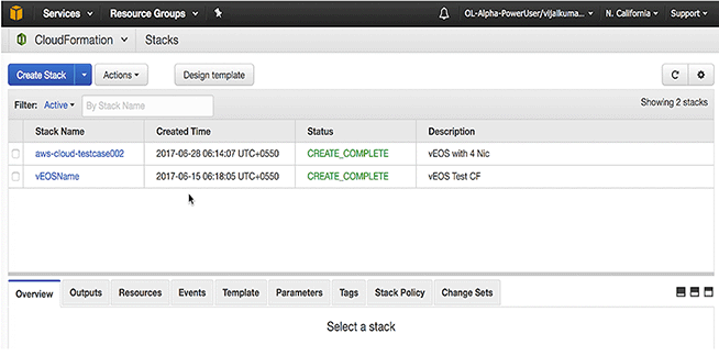
- Click Create Stack.
The page refreshes and displays the options for specifying the details for the stack.
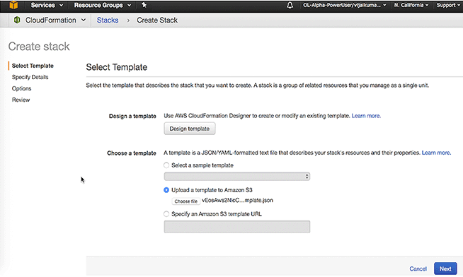
- Select a nic template for upload, and then click Next.
Note: Templates can be found in the docs directory. Click Select to choose the desired AMI.
The page refreshes and displays the options for specifying the details for the stack.
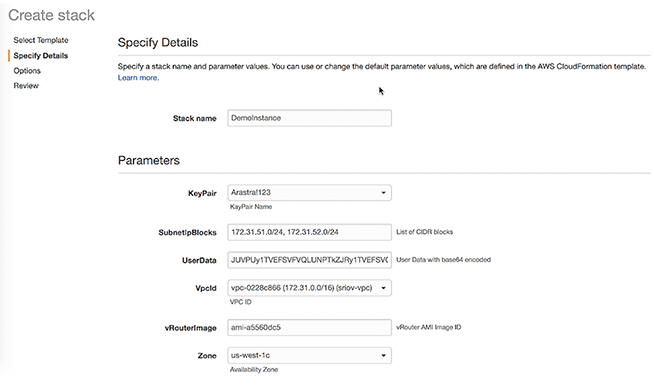
- Enter the Stack Name, Subnet IP Block for each interface, VPC ID, KeyPair Name, UserData in base64 format, and AMI ID. To convert UserData from text to base64 format, use a base64 command on MacOS or Linux machine.
router# conf t
router(config)# bash sudo su -
Arista Networks EOS shell
-bash-4.3# cat /mnt/flash/WAN-config
# Use 'mode' to set the forwarding plane for WAN. If 'mode' is set multiple times
# the last configuration takes effect.
# 'mode=linux' runs WAN with linux forwarding plane
mode=linux
# 'mode=sfe' runs WAN with dpdk forwarding plane
#mode=sfe
- Review the details and make changes if needed.
- Click Create to create the stack.
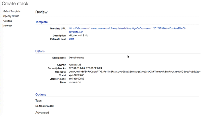
- Wait for the stack creation to complete. Resources created as part of the stack creation process can be viewed in the Resource tab.
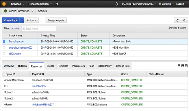
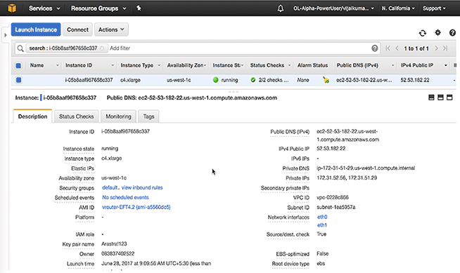
- Click the cloudeos router Instance ID to view the status of the cloudeos router instance. The Instance ID displays in the Physical ID column of the Resources tab.
Recommended Usage
When an EC2 instance with multiple network interfaces launches or starts from a stopped state, AWS cannot automatically assign a public IPv4 address. If this occurs, you can only connect to the instance over IPv4 by assigning an Elastic IP address to the primary network interface (eth0). If you prefer not to associate an Elastic IP address with the cloudeos router instance, Arista recommends attaching any additional interfaces only when the instance is active. Once the additional interfaces attach to the instance, you should avoid stopping and starting it. Instead, reboot it from the AWS console, or within the cloudeos router using the CLI or bash commands. Rebooting the instance does not cause the public IPv4 address release, but stopping the instance releases it. For instructions on associating an Elastic IP address to your instance or primary network interface, please refer to AWS Documentation.
Launching cloudeos router Instances Using EC2 AWS Marketplace
Available Options
- Assigning an IAM Role
To enable AWS services on the instance with AWS CloudWatch logs, assign an IAM role to the instance during this procedure. Assign an IAM role to the instance using one of the following methods:
- Selecting an existing IAM role.
- Creating a new IAM role provided as an option for creating a new IAM.
Refer to the following AWS documentation for details about creating EC2 key pairs and creating IAM roles.
- Creating EC2 key pairs.
- Creating an IAM role.
- Using Instance User Data
cloudeos router supports using the cloudeos router instance user data to configure cloudeos router instances at launch. This requires uploading instance user data to the instance through the Advanced Details dialog. Copy and paste a configuration into the dialog or attach a configuration file.
For details on composing user data for cloudeos router, see Using User-data for Configuration of Entities and cloudeos router Instances.
- Log in to the Amazon Management Console.
- Create an EC2 key pair and download the .pem file that contains the private key. The .pem file may download automatically.
To create an EC2 pair, go to Creating EC2 key pairs.
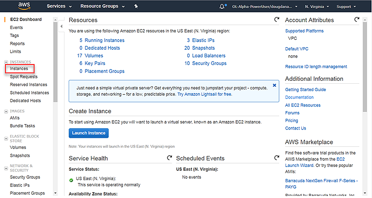
- Go to the EC2 Dashboard.
- From the EC2 Dashboard, click Instances.
The Launch Instance page appears.
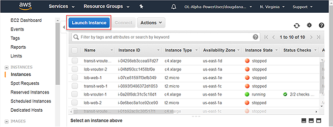
- Click Launch Instance.
Select an AMI.
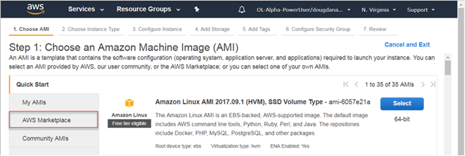
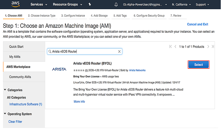
- Click AWS Marketplace.
Search for Arista cloudeos router in the search field to bring up the available cloudeos router AMIs. Select the appropriate AMI for launching.
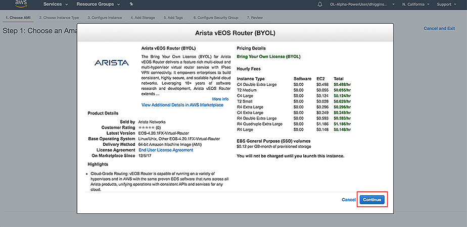
- A screen shows the user highlights, pricing details, and available instance types. Press Continue to advance.
- Click the left pane.
The Choose an Instance Type page displays.
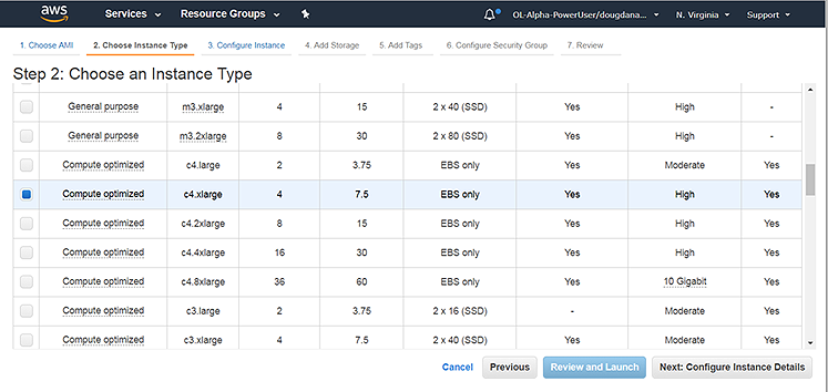
Select an instance type that meets the requirements for the cloudeos router instance.
- Click Next: Configure Instance Details.
The Configure Instance Details page displays.
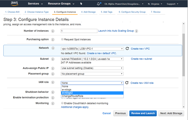
- (Optional) Create a new IAM role or select an existing IAM role. This is required to enable AWS services on the instance, for example, AWS CloudWatch logs.
- (Optional) To configure advanced details for the instance, click Advanced Details.
The Advanced Details dialog displays. Use the dialog to upload user data and configure the instance.
Do one of the following to configure the instance using user data:- Choose the Text option, then copy and paste startup-config in the text box.
- Attach the configuration as a file by clicking on the file and then choosing the configuration file to upload.
For details on composing user data for cloudeos router, see Using User-data for Configuration of Entities and cloudeos router Instances.
- From the Configure Instance Details page, click Review and Launch.
The Review Instance Launch page displays.
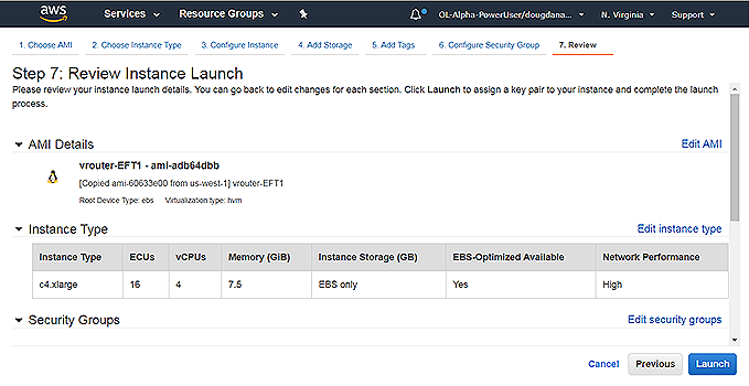
- Click Launch.
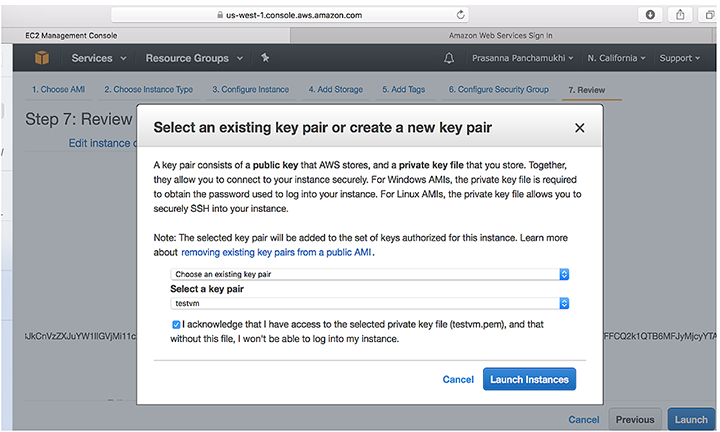
- Select the key pair created earlier in the procedure using the Select a key pair menu. In this example, use the key pair called systest.
Select the acknowledgment, and then click Launch Instances.
The Launch Status page appears, showing the status of the instance. The deployment takes a few minutes to complete.
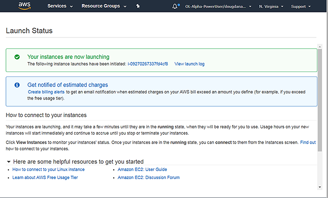
- Click the instance to view details about the instance. The link appears in the Your instances are now launching box near the top of the page.
The page shows the details for the instance.
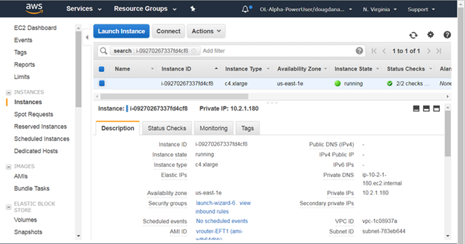
- Make sure the Instance State displays running. Wait for the status to update to running.
- (Optional) To use the existing subnet and security group for the instance, record the subnet and security group. You need this information to configure the network interfaces attached to the instance.
- (Optional) Click Connect near the top of the page.
The Connect to Your Instance dialog appears.
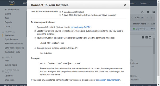
- Connect to the instance using the public or private IP address. The correct syntax is:
ssh -i <privateKey.pem> 该邮件地址已受到反垃圾邮件插件保护。要显示它需要在浏览器中启用 JavaScript。.-bash-4.3# cat /mnt/flash/WAN-config # Use 'mode' to set the forwarding plane for WAN. If 'mode' is set multiple times # the last configuration takes effect. # 'mode=linux' runs WAN with linux forwarding plane #mode=linux # 'mode=sfe' runs WAN with dpdk forwarding plane mode=sfe -bash-4.3# exit logout router(config)# reload
Complete the networking tasks for the cloudeos router instances in the gateway topology. See Network Configuration Tasks for cloudeos router Instances.
Configuring the AWS CloudWatch Logs Agent
The AWS CloudWatch Logs Agent provides a mechanism that publishes cloudeos router logs to AWS CloudWatch. Configuring the AWS CloudWatch Logs Agent ensures that the cloudeos router logs published to AWS CloudWatch conform to the selected requirements. The AWS CloudWatch Logs Agent packages with the awslogs.swix cloudeos router extension, installed and enabled by default when the cloudeos router instances launch through the AWS Marketplace.
Refer to the AWS CloudWatch User Guide to ensure that the cloudeos router instance has the right credentials for logging into AWS.
The location of the published cloudeos router logs depends on the AWS CloudWatch Logs configuration. By default, the logs publish to CloudWatch, log
group, name cloudeos routerlogs.
- Editing configuration files under the /mnt/flash/awslogs/ directory.
- Passing instance user-data. Make sure to use the correct start and end markers:
switch# show agent sfe ping

show agent sfe ping

Agent Name   Last Ping   Max Ping       Max Ping Response Seen  Last Ping Response Seen
----------------------   ------------   ----------------------  -----------------------
Sfe          1.571 ms    2209.819 ms    2019-11-15 11:14:05     2019-12-12 15:02:48
Note: Restart awslogs using sudo systemctl restart awslogs under bash. The reconfiguration only takes effect afterawslogsrestarts.
cloudeos router Log Filenames
By default, the hostname of the cloudeos router instance becomes the filename of all cloudeos router logs for that instance.
Network Configuration Tasks for cloudeos router Instances
Complete additional configuration tasks to ensure that the cloudeos router instances have the required networking configuration. The configuration tasks include the following:
- Creating the additional network interfaces required by the topology.
- Attaching the new interfaces to cloudeos router instances.
- Configuring the route table of the AWS Specific Cloud router.
Creating the Additional Network Interfaces
Creating the additional network interfaces required for the topology ensures that you can attach interfaces to cloudeos router instances. When creating the new network interfaces, use the subnet and security groups automatically assigned to the instance or specify a different subnet and security groups for the instance.
Pre-requisites:
- Subnet ID
- Security group names
Procedure
Complete these steps to create network interfaces.
- From the NETWORK & SECURITY menu, select Network Interfaces.
The page refreshes to show all of the current network interfaces.
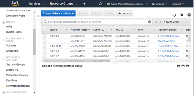
- Select Create Network Interface.
The Create Network Interface dialog displays.
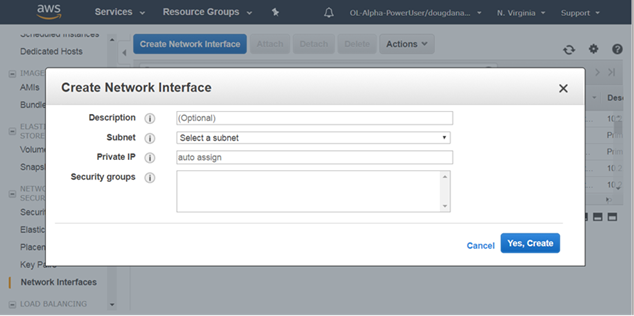
- For each network interface created, complete Steps a and b:
- Select the interface, then choose .
The Change Source/Dest Check dialog appears, displaying the name of the selected network interface.
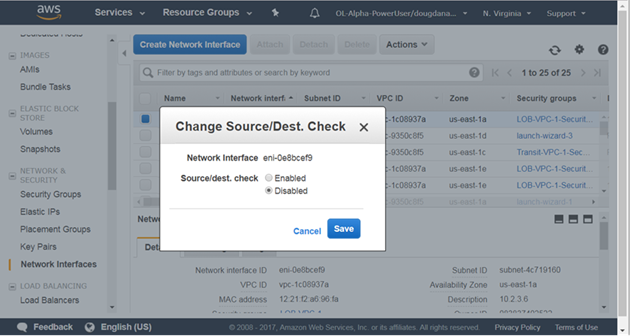
- Select Disabled, and then click Save.
- Select the interface, then choose .
Attach the new network interface to a cloudeos router instance. See Attaching the New Network Interfaces to Instances.
Attaching the New Network Interfaces to Instances
Attach the new network interfaces to cloudeos router instances. Select the new network interfaces created in the previous procedure and then attach the interfaces to cloudeos router instances.
Complete these steps to attach the new network interfaces to cloudeos router instances.
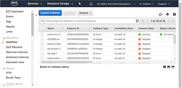
- Open the INSTANCES, and then click Instances.
The page lists all of the current network interfaces.
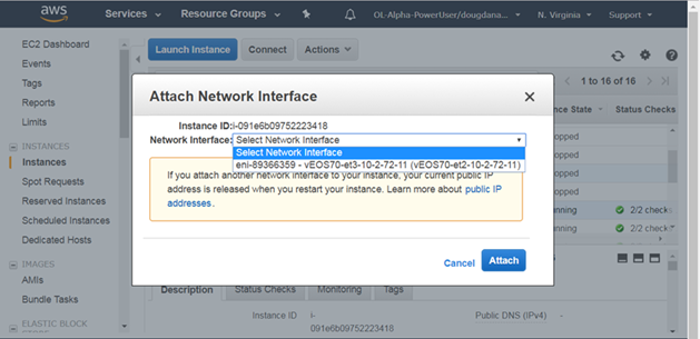
- Choose .
The Attach Network Interface dialog displays.
Configure the route table of the AWS router. See Configuring the Route Table of the AWS router.
Configuring the Route Table of the AWS router
Configure the route table of the AWS router in order to forward traffic from the AWS router to cloudeos router instances. Log into the AWS router and modify the route table entries for the cloudeos router instances to forward traffic.
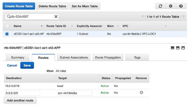
- Edit the route table entry to point to the corresponding interface of the cloudeos router in that subnet.
Example:
To reach any subnet other than 10.2.0.0/24, enter the Target as the network interface ID of the locally connected interface on the cloudeos router.
Configure the AWS CloudWatch Logs Agent. See Configuring the AWS CloudWatch Logs Agent. Configuring the Agent ensures that the cloudeos router logs publish to AWS.
cloudeos router Startup-Configuration using Instance Custom-Data
When using user data, cloudeos router supports startup configuration, AWS CloudWatch, and Cloud HA. Because user data easily configures the tasks, administrators can use this feature to quickly configure cloudeos router instances, AWS CloudWatch, and Cloud HA.
- The configuration must be separated by start and end markers.
- Markers are required at the beginning of the line.
- You must upload either text or configuration files as the cloudeosh supports these types of files.
EOS configuration for all interfaces can be transfer during deployment. The configuration takes effect as new interfaces attach to the cloudeos router.
| Entity / Configuration File / Use | Markers | File Path |
|---|---|---|
| Entity: EOS
File: EOS CLI configuration file Use: Configure cloudeos router |
%EOS-STARTUP-CONFIG-START%
%EOS-STARTUP-CONFIG-END% |
N/A |
| Entity: EOS
File: EOS CLI configuration file Use: %FORCE_USER_DATA% forcibly apply the Arista startup configs in the user custom data under the %EOS-STARTUP-CONFIG-START% and %EOS-STARTUP-CONFIG-END% ) even when it is not a first time boot of the instance. |
%FORCE-USER-DATA% |
N/A |
| Entity: AWS Logs
File: aws.conf Use: Set up AWS region |
%AWS-CONFIG-START%
%AWS-CONFIG-END% |
/mnt/flash/awslogs/aws.conf |
| Entity: AWS Logs
File: awslogs.conf Use: Configure logging parameters |
%AWSLOGS-CONFIG-START%
%AWSLOGS-CONFIG-END% |
/mnt/flash/awslogs/awsconf.conf |
| Entity: AWS Logs
File: proxy.conf Use: Configure proxy settings |
%AWS-PROXY-START%
%AWS-PROXY-END% |
/mnt/flash/awslogs/proxy.conf |
Sample Instance User-data
The following sample user data contains lines to start the instance and configure various entities.
- AWS CloudWatch logs (for the us-east-1 region)
- AWS logging parameters
- AWS proxy settings
Sample
router# platform sfe bessctl

shType "help" for more information.
localhost:10514 $ show busy
   Worker ID      Busy       PPS
           0         0         0
           1         0         0
           2         0         0

localhost:10514 $ show busy
   Worker ID      Busy       PPS
           0         0         0
           1         0         0
           2         0         0
Using the cloudeos router on Microsoft Azure
WAN router Image Updates
The process you use to update WAN router images is the standard update process used for EOS images.
For details on the steps, refer to the Arista EOS User Manual (see https://www.arista.com/en/support/product-documentation).
Launching a WAN router Azure Instance
Two methods can be used to launch a WAN router instance.
- Portal Marketplace This method launches an instance using the Azure Portal Marketplace UI.
Note: Arista recommends using only the v2 instance type for better pricing and performance while creating an instance using Azure Marketplace. Also, it enables Accelerated Networking on all the interfaces while creating an instance.
- Azure CLI 2.0: This method launches an instance using a custom template through the Azure CLI 2.0. The primary advantage of a CLI deployment is the ability to include custom data and customize your deployment.
Creating an Instance using the Portal Marketplace
Complete the following steps to create an instance using the Portal Marketplace.
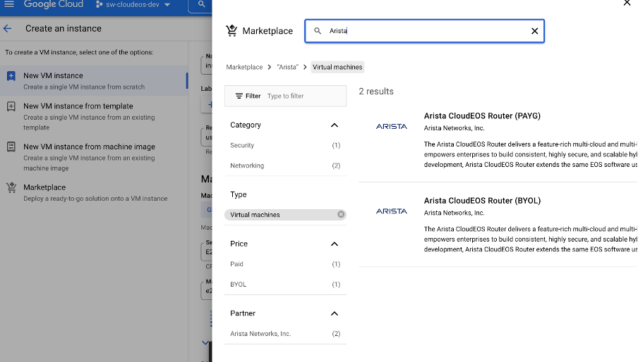
- In the search bar, type "Arista" and select Enter.
Figure 1. Type '"Arista" 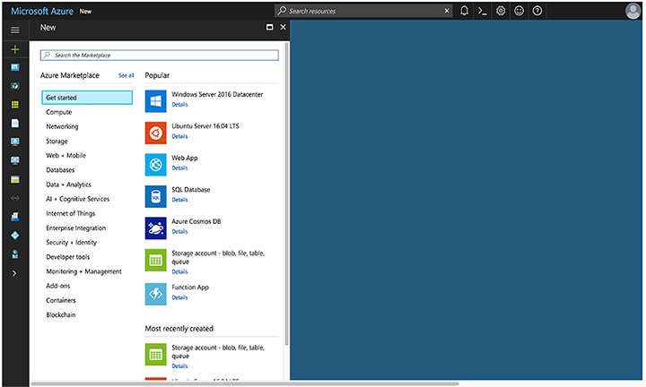
- Select the Arista offer you are interested in.
Figure 2. Arista selection 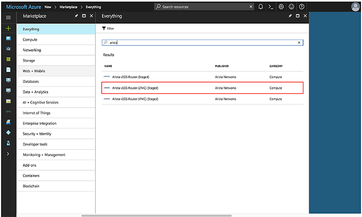
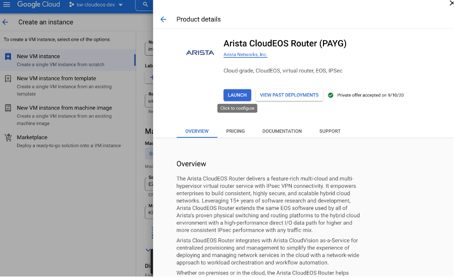
- Select Create.
Figure 3. Select "Create" 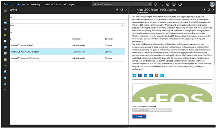
- Fill out the required information and select OK.
Figure 4. Required Information 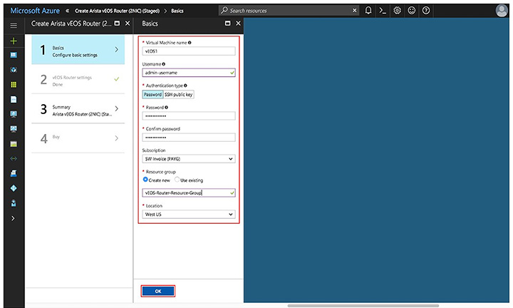
- Configure the VNet and select OK.
Figure 5. Configuring the VNet 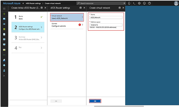
- Configure the subnets and select OK.
Figure 6. Configuring the Subnets 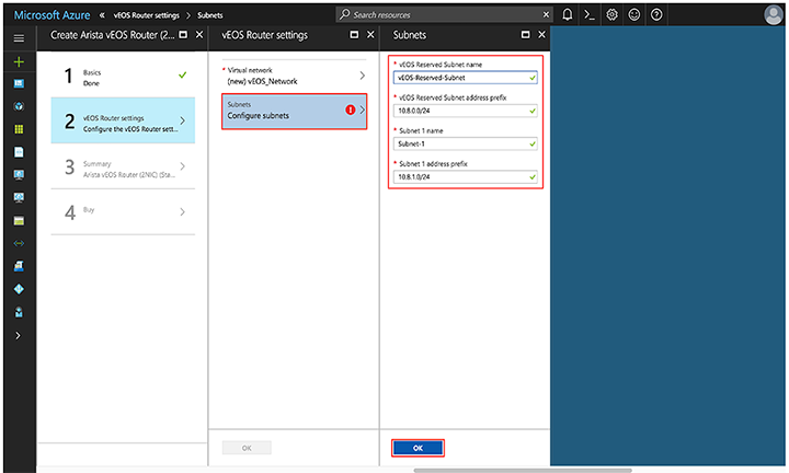
- Verify the information is correct and select OK.
Figure 7. verification 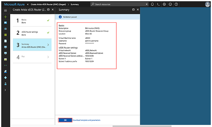
- Read the Terms and Conditions, then select Purchase.
Figure 8. Terms and Conditions 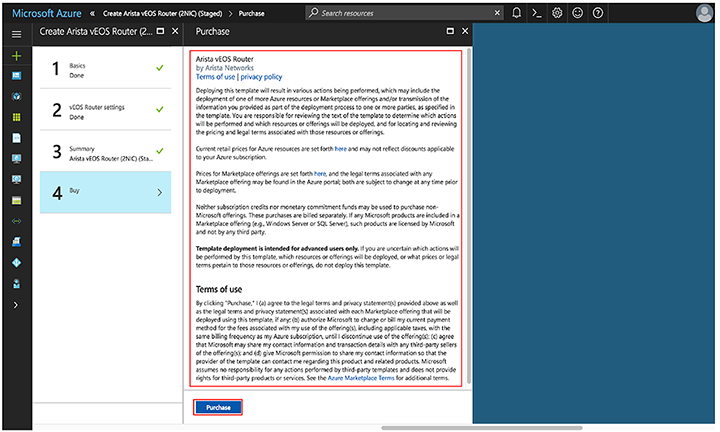
Creating an Instance under Azure CLI 2.0
To create an instance under Azure CLI 2.0, complete the following steps.
Logging into Instance
To log into an instance, complete the following steps.
- Select the item publicIP.
Figure 9. Selecting the PublicIP 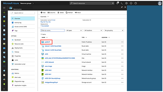
- Locate the IP address and DNS name found on the Overview page.
Figure 10. Locating the IP Address and DNS 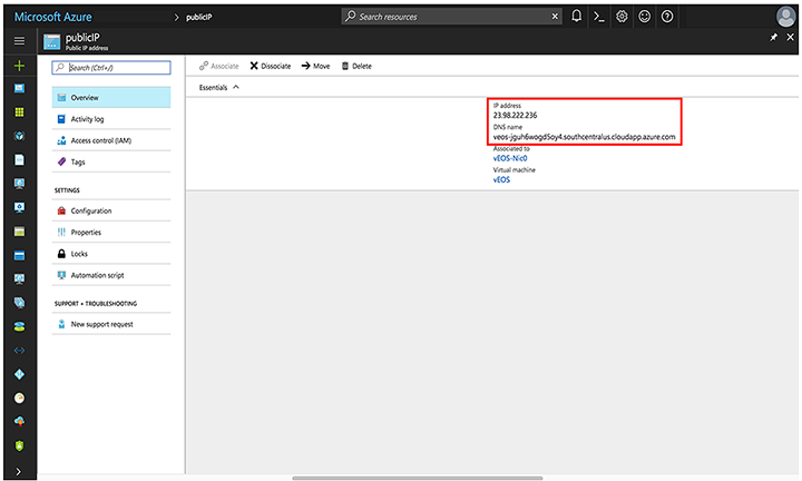 Note: If either of these fields is not populated, your instance will still be deployed. Refresh the page after a couple of minutes.
cloudeos router Startup-Configuration using Instance Custom-Data
Describes launch employing custom-data information.
Azure provideds a feature to upload custom-data during the initial launch of the veos router Instance. The administrator can upload veos router configuration using custom-data at the time of the launching of the veos router Instance.
Custom-data can be used to pass in configuration for multiple entities. Currently, only the EOS configuration is supported in Azure. This configuration must be separated by start and end markers.
|
Entity |
Markers |
File Path |
|---|---|---|
| EOS CLI configuration file |
%EOS-STARTUP-CONFIG-START% %EOS-STARTUP-CONFIG-END% |
N/A |
|
EOS CLI configuration file Use: %FORCE_USER_DATA% will forcibly apply the Arista startup configs in the user custom data under the %EOS-STARTUP-CONFIG-START% and %EOS-STARTUP-CONFIG-END% ) even when it is not a first time boot of the instance. |
%FORCE_USER_DATA% |
N/A |
- Markers must be at the beginning of the line.
- The user is expected to have tested the configurations on a live system before using the configurations to deploy the new veos router. Mis-configuration may result in an unrecoverable instance.
- EOS configuration for all interfaces can be passed on during deployment. The configuration takes effect as the new instances attach to the veos router.
Sample Instance Custom-Data
The following illustrates a sample Instance with custom-data.
%EOS-STARTUP-CONFIG-START%
! EOS startup config
username admin nopassword
username admin sshkey file flash:key.pub
%EOS-STARTUP-CONFIG-END%
Providing Startup-Configuration using Azure Custom-Data
Adding custom-data to an instance.
Currently, custom-data can only be used on instances deployed using the Azure CLI 2.0.
To add custom-data to an instance, the custom-data must be provided as a single-line value with '\n' delimiting newlines.
Use the single_line_json.sh script to convert your custom-data into this format.
#!/usr/bin/bash
cat $1 | python -c 'import json, sys; print( json.dumps( sys.stdin.read() ) )'
The usage of the script is as follows:
./single_line_json.sh user_data.txt
Copy and paste the generated output into the customData value field of the JSON parameters file.
Troubleshooting Instance
To troubleshoot the instance, complete the following steps.
- Select the item WAN router.
Figure 11. Select the WAN router 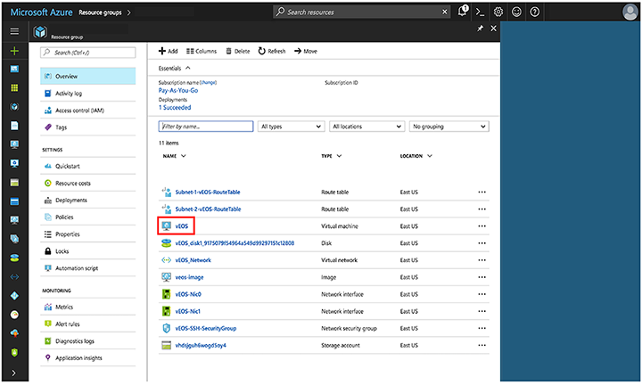
- Note the status of the VM. It should be "Creating", "Starting", or "Running".
Figure 12. Status of the VM 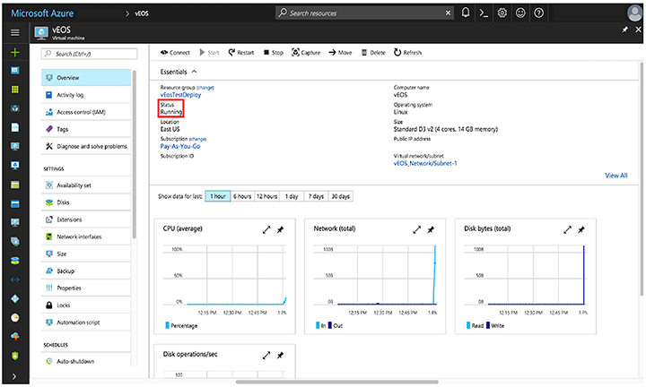
- Check the boot diagnostics for any error messages or warnings.
Figure 13. Error Messages and Warnings 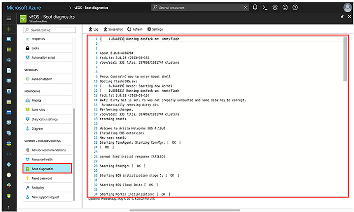
Resources
Additional resources.
- How To Deploy Resources - https://docs.microsoft.com/en-us/azure/azure-resource-manager/resource-group-template-deploy-cli
Arista WAN on Google Cloud Platform (GCP)
Arista WAN is now supported on Google Cloud Platform (GCP) and other public and private clouds.
Overview
Arista WAN
Arista WAN is a cloud-grade and feature-rich virtual router for Google Cloud. This software-only release of EOS software is supported on public clouds and on customer premises equipment running Linux and VMware hypervisors. By bringing advanced network telemetry and secure IPSec VPN connectivity in a software-only package, WAN provides a consistent, secure, and universal approach to hybrid cloud networking for any virtualized cloud deployment.
This release of WAN is available as a software subscription in Google Cloud Launcher following a BYOL and PAYG license model. For the BYOL instance, a WAN license activation key must be obtained separately from Arista, unlocking the platform from a default performance limit of 10 Mbps and enabling IPsec encrypted VPNs. The system will automatically install the license for the PAYG instance so customers can use all features, including IPsec and uncapped throughput. For more information about licensing, refer to License Management.
Deploying Arista WAN on GCP
- Locate the WAN listing in the Google Cloud Launcher, then select LAUNCH ON COMPUTE ENGINE.
- Fill out the relevant fields in the deployment screen, then select Deploy.
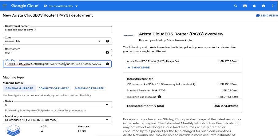
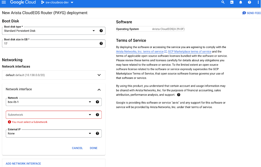 Update zones, names, and other details as needed. Also, add a user name with a public SSH key for that user. You can also change the machine type depending on the performance requirements of the VM and add more than one NIC if needed.Note: When adding an SSH public key, paste it without extra spaces or new lines. For example, the public key looks similar to this.
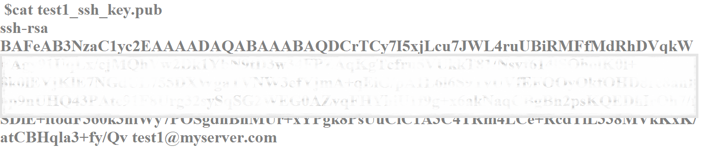
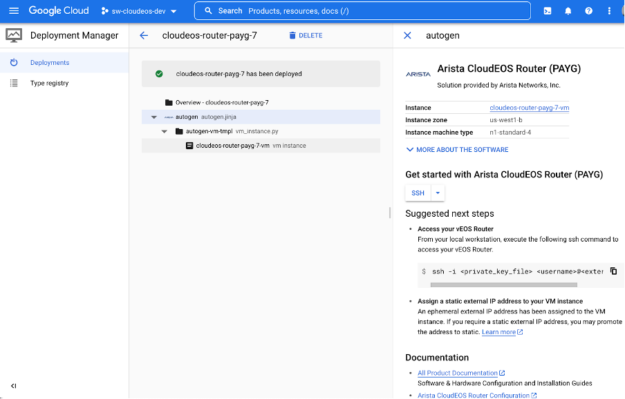
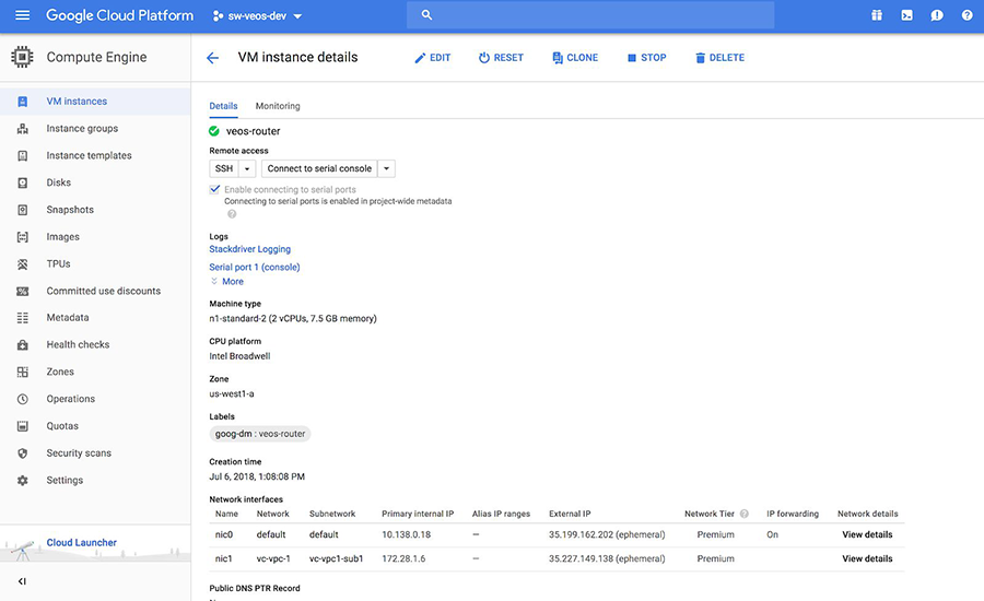
- After deployment, you will find the information about your WAN instance on the post-deployment screen.
Logging into Arista WAN
- From the post-deployment screen, select vm instance.
.png)
- Select MANAGE RESOURCE.
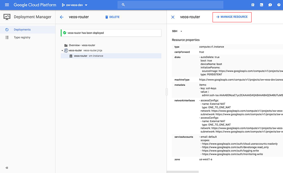
- Locate the External IP.
WAN router Startup-Configuration using Instance Custom-Data
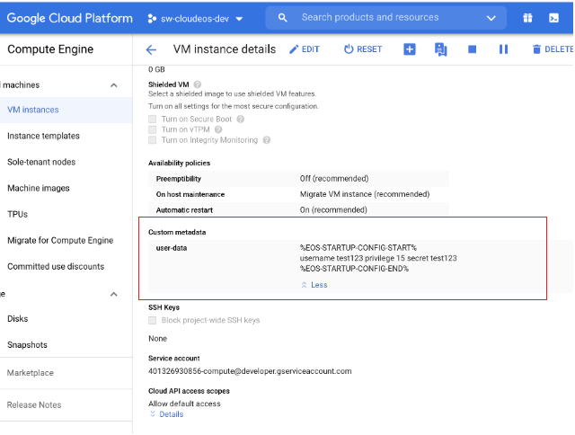
This section discusses the use of custom-data during the initial deployment of the veos router instance, GCP provides an option to upload custom-data. The custom-data used passes in the configuration for multiple entities. Currently, GCP supports only the EOS configuration. This configuration is separated using start and end markers.
The administrator can upload veos router configuration using custom-data while launching a router instance through the portal, as shown below. Note that the custom-data works only during the first boot.
- Markers must be at the beginning of the line.
- The user is expected to have tested the configurations on a live system before using the configurations to deploy the new veos router. Mis-configuration may result in an unrecoverable instance.
- EOS configuration for all interfaces is passed on during the deployment. The configuration takes effect as the new instances attach to the veos router.
|
Entity |
Markers |
File Path |
|---|---|---|
| EOS CLI configuration file |
|
N/A |
|
EOS CLI configuration file Use: %FORCE_USER_DATA% will forcibly apply the Arista startup configs in the user custom data under the %EOS-STARTUP-CONFIG-START% and %EOS-STARTUP-CONFIG-END% ) even when it is not a first time boot of the instance. |
%FORCE_USER_DATA% |
N/A |
Configuring custome-data for GCP instance through portal.
Using the cloudeos router on KVM and ESXi
This section discusses the system requirements, installation, and configuration procedures for the cloudeos router on the hypervisor.
Server
A server can be either a hardware or software entity.
A hardware server is a physical computer that executes the virtual machine manager or hypervisor and all the virtual machines, also known as the host machine.
A software server is the hypervisor or virtual machine manager that hosts and manages the virtual machines. It is also referred to as the host.
VMware ESXi Minimum Server Requirements
- Ethernet NICs must be SR-IOV capable
- BIOS / System Firmware support for SR-IOV
- 8 GB free disk space
- 16 GB RAM
- 4 cores running a minimum 2.4GHz or greater and 16 GB memory
- Intel VT-x and VT-d support
- Ethernet NICs must be SR-IOV capable
- BIOS / System Firmware support for SR-IOV
KVM Requirements
cloudeos router must be deployed on an x86-64 architecture server running a KVM hypervisor.
- 8 GB free disk space
- 16 GB RAM
- x86-64 Server class CPU (32-bit CPUs not supported) with
- Intel VT-x or AMD-V support for CPU Virtualization
- Intel VT-d or AMD-IOMMU support for PCIe passthrough
- Intel AES-NI support
- 4 CPU cores running at 2.4GHz.
- Ethernet NICs must be SR-IOV capable
- BIOS / System Firmware support for SR-IOV
Supported Topologies
VMware ESXi Hypervisor
This section discusses the launch sequence for VMware ESXi 8.0.
Launching VMware ESXi 6.0 and 6.5
Launching VMWare ESXi 6 and ESXi 6.5 for WAN.
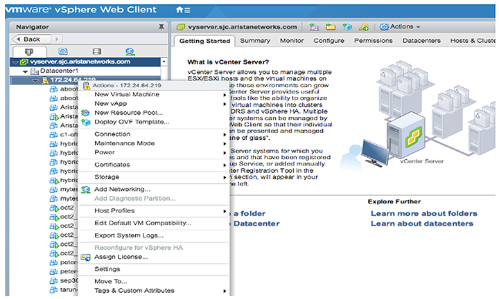
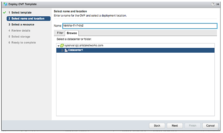
ESXi has two different user interfaces for managing the ESXi host: the vSphere Web Client and the ESXi Web Client. The following required task launches VMware 6.0 and 6.5 and provides a general guideline on the steps involved in deploying virtual machines with an OVF/OVA template.
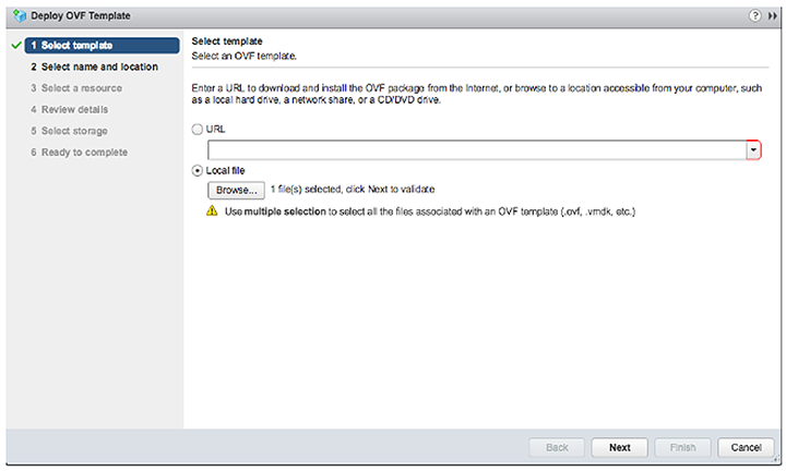
- From the vCenter Server WEB-UI navigator, select Deploy OVF template.
- Select the OVA file from the local machine.
- Select the name and location for WAN deployment.
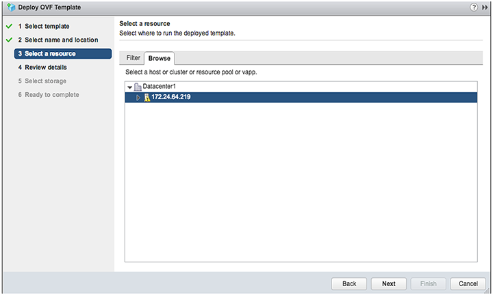
- Select the host, cluster, resource pool, or VAPP.
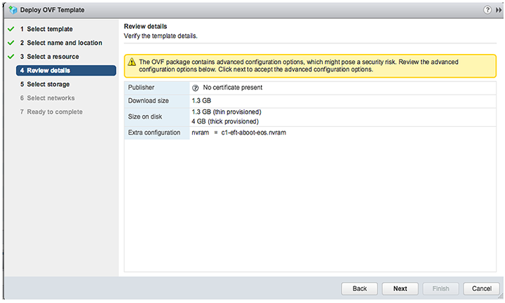
- Verify the template details.
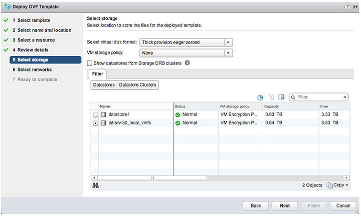
- Select Thick provision eager zeroed from the datastore.
- Select the default network.
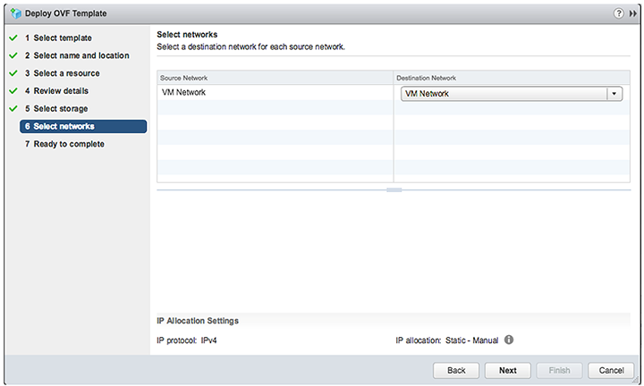
- Complete the launch process.
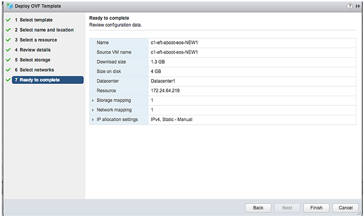
- The deployment progress displays under the Recent Tasks tab at the bottom of the page after the deployment completes. Then, power on the VM.
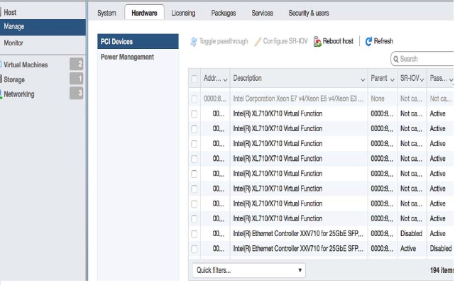
Enabling SR-IOV or PCI Passthrough on ESXi
Describes how to enable single route input or output vitalization (SR-IOV) or PCI passthrough on VMware ESXi.
To enable SR-IOV or PCI passthrough on ESXi, complete the following steps.
- Navigate to the ESXi host Manage, then select the Hardware tab.
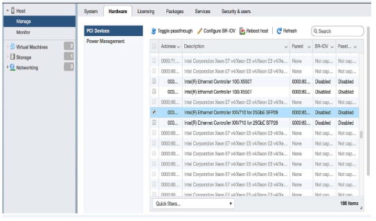
- Use the Toggle passthrough or the Configure SR-IOV selection to activate the mode.
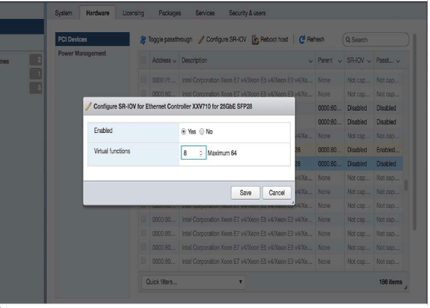
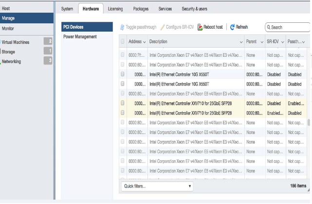
- After reboot, the NIC reflects the changes. For SR-IOV, new virtual function devices (VF) are created.
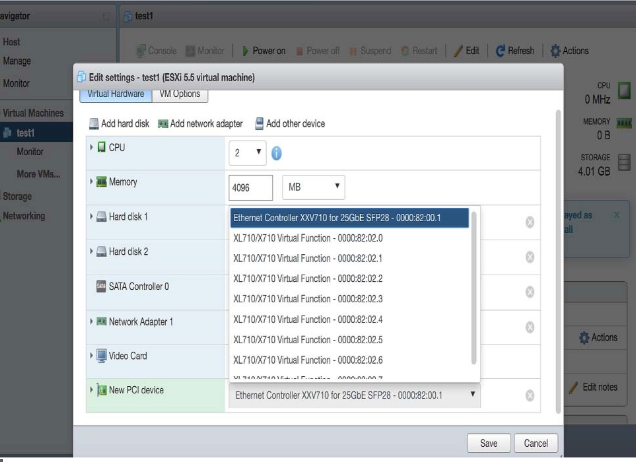
- Edit the VM and select Add other device, then select PIC Device to create the New PIC Device for the VM.
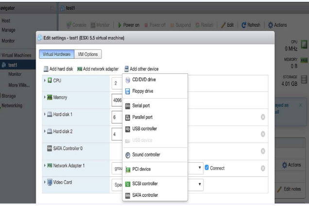
- Select the New PIC Device to use the SR-IOV VF or PIC Passthrough device.
KVM
This section discusses the system requirements, installation and configuration procedures for the cloudeos router.
Server
A hardware server is the physical computer that executes the virtual machine manager or hypervisor and all the virtual machines. This is also called the host machine.
A software server is the hypervisor or virtual machine manager that hosts and manages the virtual machines. It is also referred to as the host. In this document, the software server comprises RedHat Linux with virtualization support (KVM).
System Requirements
The following outlines the minimum system requirements for using KVM.
Minimum Server Requirements
Any VMware supported ESXi server hardware.
- RedHat 7x with virtualization support.
- Install Libvirt by executing virsh list. Python 2.7+ is required to run the installation script vSphere 6.0.
veos Virtual Machine
- 2 vCPUs
- 4GB Memory
- 8G Free disk space
- 16 vCPUs
- 8 network interfaces
Supported Images
| Image Name | File Name | Details |
| KVM veos image | EOS.qcow2 | Image Hard Disk that contains veos. This file can grow as agents in veos generates logs and traces. |
Using Libvirt to Manage cloudeos router VM on KVM
Libvirt is an open source library that provides cloudeos router management for virtual machines.
Libvirt supports many functions such as creating, updating, and deleting VMs.
The complete Libvirt command reference can be found at http://libvirt.org/virshcmdref.html.
Define a new VM
Define a domain from an XML file using the virsh define <vm-definition-file.xml > command. This defines the domain, but it does not start the domain.
The definition file has vm-name, CPU, memory, network connectivity, and a path to the image. Review the parameters at https://libvirt.org/formatdomain.html.
Undefine the Inactive Domain
Undefine the configuration for the inactive domain by using the virsh undefine <vm-name> and specifying the domain name.
Start VM
Start a previously defined or inactive domain using the virsh start <vm-name> command.
Stop VM
Terminate a domain immediately by using the virsh destroy <vm-name> command.
Managing Networks
- The virsh net-define <network-definition-file.xml> command.
- The virsh net-undefine network-name command removes an inactive virtual network from the libvirt configuration.
- The virsh start network-name command manually starts a virtual network that is not running.
- The virsh destroy network-name command shuts down a running virtual network.
Launching veos in LinuxBridge mode
Use the script SetupLinuxBridge.pyc usage python SetupLinuxBridge.pyc <bridge- name>
- virsh define <veos define file say veos.xml>
- virsh start <veos-name>
- virsh console <veos-name>
<domain type='kvm'>
<!-- veos name, cpu and memory settings -->
<name>kvs1-veos1</name>
<memory unit='MiB'>4096</memory>
<currentMemory unit='MiB'>4096</currentMemory>
<vcpu placement='static'>2</vcpu>
<resource>
<partition>/machine</partition>
</resource>
<cpu mode='host-model'/>
<os>
<type arch='x86_64'>hvm</type>
<boot dev='cdrom'/>
<boot dev='hd'/>
</os>
<features>
<acpi/>
<apic/>
<pae/>
</features>
<clock offset='utc'/>
<on_poweroff>destroy</on_poweroff>
<on_reboot>restart</on_reboot>
<on_crash>restart</on_crash>
<devices>
 <emulator>/usr/bin/qemu-system-x86_64</emulator>
 <disk type='file' device='disk'>
  <driver name='qemu' type='qcow2' cache='directsync'/>
  <source file='/path_to_file/cloudeos.qcow2'/>
  <target dev='hda' bus='ide'/>
  <alias name='ide0-0-0'/>
  <address type='drive' controller='0' bus='0' target='0' unit='0'/>
 </disk>
<disk type='file' device='cdrom'>
<driver name='qemu' type='raw'/>
<source file='/path_to_file/Aboot-veos-serial.iso'/>
<target dev='hdc' bus='ide'/>
<readonly/>
<alias name='ide0-1-0'/>
<address type='drive' controller='0' bus='1' target='0' unit='0'/>
</disk>
<controller type='usb' index='0'>
<alias name='usb0'/>
<address type='pci' domain='0x0000' bus='0x00' slot='0x01' function='0x2'/>
</controller>
<controller type='pci' index='0' model='pci-root'>
<alias name='pci0'/>
</controller>
<controller type='ide' index='0'>
<alias name='ide0'/>
<address type='pci' domain='0x0000' bus='0x00' slot='0x01' function='0x1'/>
</controller>
<!-- In this case management is connected to linux bridge -->
<interface type='bridge'>
<source bridge='brMgmt'/>
<model type='virtio'/>
<address type='pci' domain='0x0000' bus='0x00' slot='0x03' function='0x0'/>
</interface>
<serial type='pty'>
<source path='/dev/pts/4'/>
<target port='0'/>
<alias name='serial0'/>
<target port='0'/>
<alias name='serial0'/>
</serial>
<console type='pty' tty='/dev/pts/4'>
<source path='/dev/pts/4'/>
<target type='serial' port='0'/>
<alias name='serial0'/>
</console>
<input type='mouse' bus='ps2'/>
<graphics type='vnc' port='5903' autoport='yes' listen='127.0.0.1'>
<listen type='address' address='127.0.0.1'/>
</graphics>
<video>
<model type='cirrus' vram='9216' heads='1'/>
<alias name='video0'/>
<address type='pci' domain='0x0000' bus='0x00' slot='0x02' function='0x0'/>
</video>
<memballoon model='virtio'>
<alias name='balloon0'/>
<address type='pci' domain='0x0000' bus='0x00' slot='0x04' function='0x0'/>
</memballoon>
<!-- Has two data ports on different vlans
Cut and paste the more interface elements for more interfaces but increment the slot number.
Note that brWAN and brLAN bridges need to be created beforehand -->
<interface type='bridge'>
<source bridge='brWAN'/>
<model type='virtio'/>
<address type='pci' domain='0x0000' bus='0x00' slot='5' function='0x0'/>
</interface>
<interface type='bridge'>
<source bridge='brLAN'/>
<model type='virtio'/>
<address type='pci' domain='0x0000' bus='0x00' slot='6' function='0x0'/>
</interface>
</devices>
</domain>
Example Deployment
VIRTIO & Linux Bridging Deployment
veos can employ para-virtualized network I/O interfaces, which in Linux KVM is also known as Virtio. Each NIC is connected to a unique underlying Linux layer-2 bridge in the hypervisor, providing uplink access.
- Ethernet1 connects to the physical Ethernet port that connects to the WAN through a LinuxBridge. The router is configured with a WAN IP address on this port.
- Ethernet2 connects to the physical ethernet port that connects to the LAN through a LinuxBridge.
- The server IP address in the diagram is assumed to be configured on the LAN LinuxBridge device.

Setting Up the Host for Single Root I/O Virtualization (SR-IOV)
Single Root I/O Virtualization (SR-IOV) allows a single PCIe physical device under a single root port to appear as multiple physical devices to the hypervisor.
- Verify the IOMMU Support.
Use the virt-host-validate Linux command to check the support of IOMMU (input/output memory management unit). If it does not "PASS" for IOMMU, check the BIOS and kernel settings.
Review the following example output:
[arista@solution]$ virt-host-validate QEMU: Checking for device assignment IOMMU support : PASS QEMU: Checking if IOMMU is enabled by kernel : PASS - Verify the supported drivers.
Ensure the PCI device with SR-IOV capabilities is detected. An INTEL 82599 ES network interface card supporting SR-IOV is detected in the example below.
Verify the ports and NIC IDs in bold in the lspci | grep Ethernet Linux command output below.
# lspci | grep Ethernet 01:00.0 Ethernet controller: Intel Corporation I350 Gigabit Network Connection (rev 01) 01:00.1 Ethernet controller: Intel Corporation I350 Gigabit Network Connection (rev 01) 01:00.2 Ethernet controller: Intel Corporation I350 Gigabit Network Connection (rev 01) 01:00.3 Ethernet controller: Intel Corporation I350 Gigabit Network Connection (rev 01) 81:00.0 Ethernet controller: Intel Corporation I350 Gigabit Network Connection (rev 01) 81:00.1 Ethernet controller: Intel Corporation I350 Gigabit Network Connection (rev 01) 81:00.2 Ethernet controller: Intel Corporation I350 Gigabit Network Connection (rev 01) 81:00.3 Ethernet controller: Intel Corporation I350 Gigabit Network Connection (rev 01) 82:00.0 Ethernet controller: Intel Corporation 82599ES 10-Gigabit SFI/SFP+ Network Connection (rev 01) 82:00.1 Ethernet controller: Intel Corporation 82599ES 10-Gigabit SFI/SFP+ Network Connection (rev 01) 83:00.0 Ethernet controller: Intel Corporation 82599ES 10-Gigabit SFI/SFP+ Network Connection (rev 01) 83:00.1 Ethernet controller: Intel Corporation 82599ES 10-Gigabit SFI/SFP+ Network Connection (rev 01) - Verify the driver kernel is active.
After confirming the device support, the driver kernel module should load automatically by the kernel. To verify the driver kernel is active, use the lsmod | grep igb Linux command.
[root@kvmsolution]# lsmod | grep igb igb 197328 0 ptp 19231 2 igb,ixgbe dca 15130 2 igb,ixgbe i2c_algo_bit 13413 2 ast,igb i2c_core 40756 6 ast,drm,igb,i2c_i801,drm_kms_helper,i2c_algo_bit - Activate Virtual Functions (VFs).
The maximum number of supported virtual functions depends on the type of card. To activate the VFs, use [arista@localhost]$ /sys/class/net/<Device_Name>/device/sriov_numvfs or the method shown in the example below, it shows that the PF identifier 82:00.0 supports a total of 63 VFs.
Example
[arista@localhost]$ cat/sys/bus/pci/devices/0000\:82\:00.0/sriov_totalvfs 63To activate the seven VFs per PFs and make them persistent after reboot, add the line options igb max_vfs=7 in ixgbe.conf, and the sriov.conf files in /etc/modprobe.d
- Use the rmmod ixgbe and modprobe ixgbe Linux commands to unload and reload the module.
- Verify the VFs are detected.
Verify the VFs are detected using the lspci | grep Ethernet Linux command. For the two identifiers 82:00.0 and 82:00.1, 14 VFs are detected.
# lspci | grep Ethernet 82:00.0 Ethernet controller: Intel Corporation 82599ES 10-Gigabit SFI/SFP+ Network Connection (rev 01) 82:00.1 Ethernet controller: Intel Corporation 82599ES 10-Gigabit SFI/SFP+ Network Connection (rev 01) 82:10.0 Ethernet controller: Intel Corporation 82599 Ethernet Controller Virtual Function (rev 01) 82:10.1 Ethernet controller: Intel Corporation 82599 Ethernet Controller Virtual Function (rev 01) 82:10.2 Ethernet controller: Intel Corporation 82599 Ethernet Controller Virtual Function (rev 01) 82:10.3 Ethernet controller: Intel Corporation 82599 Ethernet Controller Virtual Function (rev 01) 82:10.4 Ethernet controller: Intel Corporation 82599 Ethernet Controller Virtual Function (rev 01) 82:10.5 Ethernet controller: Intel Corporation 82599 Ethernet Controller Virtual Function (rev 01) 82:10.6 Ethernet controller: Intel Corporation 82599 Ethernet Controller Virtual Function (rev 01) 82:10.7 Ethernet controller: Intel Corporation 82599 Ethernet Controller Virtual Function (rev 01) 82:11.0 Ethernet controller: Intel Corporation 82599 Ethernet Controller Virtual Function (rev 01) 82:11.1 Ethernet controller: Intel Corporation 82599 Ethernet Controller Virtual Function (rev 01) 82:11.2 Ethernet controller: Intel Corporation 82599 Ethernet Controller Virtual Function (rev 01) 82:11.3 Ethernet controller: Intel Corporation 82599 Ethernet Controller Virtual Function (rev 01) 82:11.4 Ethernet controller: Intel Corporation 82599 Ethernet Controller Virtual Function (rev 01) 82:11.5 Ethernet controller: Intel Corporation 82599 Ethernet Controller Virtual Function (rev 01) - Locate the serial numbers for the PFs and VRFs
Locate the serial numbers for the PFs and VFs. The Linux virsh nodedev-list | grep 82 command below displays the serial number for identifiers 82:00.0 and 82:00.1. The first two numbers are the serial numbers for the PFs, and the remaining is the serial numbers for the VFs.
# virsh nodedev-list | grep 82 pci_0000_82_00_0 pci_0000_82_00_1 pci_0000_82_10_0 pci_0000_82_10_1 pci_0000_82_10_2 pci_0000_82_10_3 pci_0000_82_10_4 pci_0000_82_10_5 pci_0000_82_10_6 pci_0000_82_10_7 pci_0000_82_11_0 pci_0000_82_11_1 pci_0000_82_11_2 pci_0000_82_11_3 pci_0000_82_11_4 pci_0000_82_11_5 - Select the serial number of the VF.
Select the serial number of the VF that will attach to the VM (veos). Locate the bus, slot, and function parameters using the Linux virsh nodedev-dumpxml <serial number> command. For example, serial number pci_0000_82_11_1 displays the following details.
# virsh nodedev-dumpxml pci_0000_82_11_1 <device> <name>pci_0000_82_11_1</name> <path>/sys/devices/pci0000:80/0000:80:02.0/0000:82:11.1</path> <parent>computer</parent> <driver> <name>ixgbevf</name> </driver> <capability type='pci'> <domain>0</domain> <bus>130</bus> <slot>17</slot> <function>1</function> <product id='0x10ed'>82599 Ethernet Controller Virtual Function</product> <vendor id='0x8086'>Intel Corporation</vendor> <capability type='phys_function'> <address domain='0x0000' bus='0x82' slot='0x00' function='0x1'/> </capability> <iommuGroup number='71'> <address domain='0x0000' bus='0x82' slot='0x11' function='0x1'/> </iommuGroup> <numa node='1'/> <pci-express> <link validity='cap' port='0' width='0'/> <link validity='sta' width='0'/> </pci-express> </capability> </device> - Create a new Interface.
Shutdown the veos VM if running. Open the XML file for the specific veos VM for editing using the Linux command virsh edit <vm-name>. In the interface section, create a new interface by adding the details as shown in the example. The
bus,slot, andfunctionvalues use a hexadecimal format of the decimal values found in Step 7.<interface type='hostdev' managed='yes'> <source> <address type='pci' domain='0x0000' bus='0x82' slot='0x11' function='0x1'/> </source> </interface> - Start the veos VM. Verify the added interface on the VM. Using the command ethtool -i et9 to verify that the driver for the added interface is ixgbevf.
switch(config)# show interface status
Port   Name    Status       Vlan     Duplex Speed  Type     Flags
       Et9     notconnect   routed   unconf        unconf   10/100/1000
       Ma1     connected    routed   a-full        a-1G     10/100/1000

[admin@veos]$ ethtool -i et9
driver: ixgbevf
version: 2.12.1-k
firmware-version:
bus-info: 0000:00:0c.0
supports-statistics: yes
supports-test: yes
supports-eeprom-access: no
supports-register-dump: yes
supports-priv-flags: no
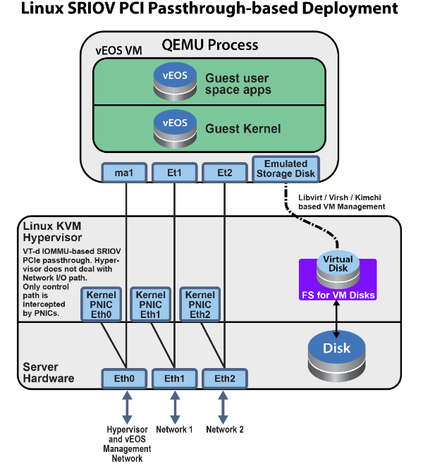
Launching SR-IOV
veos can also use PCIE SR-IOV I/O interfaces. Each SRI-OV NIC passes through to the VM such that network I/O does not hit the hypervisor. The hypervisor and multiple VMs can share the same NIC card in this model.
- Higher Performance ~ 2x.
- Better latency and jitter characteristics.
- veos directly receives physical port state indications from the virtual device.
- Using SR-IOV, virtualize the NIC.
- The NICs have a built-in bridge to do basic bridging.
- Avoids software handling of the packets in the kernel.
Setting Up the Host and Launching PCI Pass-through
Set up a networking device to use PCI pass-through.
- Identify Available Physical Functions.
Similar to the SR-IOV, identify an available physical function, a NIC, and the identifier. The lspci | grep Ethernet Linux command displays the available physical functions.
In this example, 82:00.0 Ethernet controller: Intel Corporation 82599ES 10-Gigabit SFI/SFP+ Network Connection is the physical function, and 82:00.0 is the device identification code.
# lspci | grep Ethernet 01:00.0 Ethernet controller: Intel Corporation I350 Gigabit Network Connection (rev 01) 01:00.1 Ethernet controller: Intel Corporation I350 Gigabit Network Connection (rev 01) 01:00.2 Ethernet controller: Intel Corporation I350 Gigabit Network Connection (rev 01) 01:00.3 Ethernet controller: Intel Corporation I350 Gigabit Network Connection (rev 01) 81:00.0 Ethernet controller: Intel Corporation I350 Gigabit Network Connection (rev 01) 81:00.1 Ethernet controller: Intel Corporation I350 Gigabit Network Connection (rev 01) 81:00.2 Ethernet controller: Intel Corporation I350 Gigabit Network Connection (rev 01) 81:00.3 Ethernet controller: Intel Corporation I350 Gigabit Network Connection (rev 01) 82:00.0 Ethernet controller: Intel Corporation 82599ES 10-Gigabit SFI/SFP+ Network Connection (rev 01) 82:00.1 Ethernet controller: Intel Corporation 82599ES 10-Gigabit SFI/SFP+ Network Connection (rev 01) 83:00.0 Ethernet controller: Intel Corporation 82599ES 10-Gigabit SFI/SFP+ Network Connection (rev 01) 83:00.1 Ethernet controller: Intel Corporation 82599ES 10-Gigabit SFI/SFP+ Network Connection (rev 01) - Verify Available Physical Functions.
Verify the available physical functions by using the virsh Linux commands.
[arista@solution]$ virsh nodedev-list | grep 82_00_0
pci_0000_82_00_0
[arista@solution]$ virsh nodedev-dumpxml pci_0000_82_00_0
<device>
  <name>pci_0000_82_00_0</name>
  <path>/sys/devices/pci0000:80/0000:80:02.0/0000:82:00.0</path>
  <parent>pci_0000_80_02_0</parent>
  <driver>
    <name>vfio-pci</name>
  </driver>
  <capability type='pci'>
    <domain>0</domain>
    <bus>130</bus>
    <slot>0</slot>
    <function>0</function>
    <product id='0x10fb'>82599ES 10-Gigabit SFI/SFP+ Network Connection</product>
    <vendor id='0x8086'>Intel Corporation</vendor>
    <capability type='virt_functions' maxCount='64'/>
In this example, the domain is 0 (Hex domain=0x0), the bus is 130 (Hex bus=0x82), the slot is 0 (Hex slot=0x0), and the function is 0 (Hex function=0x0).
With the domain, bus, slot, and function information, construct the device entry and add it to the VMs XML configuration.
<devices> ... <hostdev mode='subsystem' type='pci' managed='yes'> <source> <address domain='0x0000' bus='0x82' slot='0x00' function='0x0'/> </source> </hostdev> - Verify the NIC was detected by the VM.
When starting the VM, the VM should detect NIC.
router# bash Arista Networks EOS shell [admin@veos1 ~]$ lspci | grep Ethernet 00:03.0 Ethernet controller: Intel Corporation 82599EB 10-Gigabit SFI/SFP+ Network Connection (rev 01) 00:05.0 Ethernet controller: Red Hat, Inc Virtio network device [admin@veos ~]$ - Verify Driver Requirements.
If veos supports the NIC and meets any other driver requirements, use the corresponding Ethernet interfaces on the veos. Use the show interface command to display the available veos Ethernet interfaces.
router# show interface  status
Port   Name   Status       Vlan     Duplex Speed  Type   Flags
       Et1    connected    routed   full          10G    10/100/1000
       Ma1    connected    routed   a-full        a-1G   10/100/1000

router#bash
bash-4.3# ethtool -i et1
driver: ixgbe
version: 4.2.1-k
firmware-version: 0x18b30001
bus-info: 0000:00:03.0
supports-statistics: yes
supports-test: yes
supports-eeprom-access: yes
supports-register-dump: yes
supports-priv-flags: no
Example Deployment
veos can use passthrough I/O interfaces where the network I/O does not hit the hypervisor. In this model, the VM owns the entire network card, thus fully bypassing the hypervisor.
- SR-IOV has the following advantages over LinuxBridge Higher Performance ~ 2x.
- Better latency and jitter characteristics.
- veos directly receives physical port state indications from the virtual device.
Figure 16. Linux PCI Passthrough-based Deployment 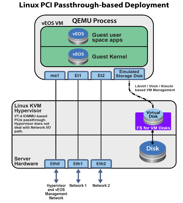
Using the cloudeos router On an Arista Appliance (DCA-200-veos)
Overview
The appliance used to host virtual cloudeos utilizes a KVM Hypervisor and possesses two 2x10G SFP+ NIC cards for data traffic and two 1G ports for management traffic.
Specify the resources for the cloudeos VM instance including CPU cores, memory, and interfaces based on your network deployment models and desired performance. Use the cloudeos launcher script, dca-200- veos-setup-vm.py, to efficiently launch new cloudeos router instances with appropriate resources and network interface setups.
Hardware
- Two sockets with 10 CPU cores each. Configure optimal cloudeos router performance by turning off hyperthreading on the hardware.
- 64 GB memory
- Two 2 x 10G SFP+ NIC cards for a total of 4 10G NIC ports for data traffic
- 2 x 1G ports (eno1 and eno2) for management
- 2 x 1G ports (eno3 and eno4) NOT used by cloudeos router launcher scripts.
- Integrated Dell Remote Access Controller (iDRAC)
Interfaces
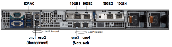
Management Interfaces
The appliance has 4 physical 1G ports called eno1, eno2, eno3, and eno4. eno1 and eno2 aggregate to a bonded interface device0 in 802.3ad mode. They must connect to one or more network devices supporting Link Aggregation Control Protocol (LACP). The bonded interface device0 internally connects to a Linux bridge named devicebr. The cloudeos launcher script sets up the cloudeos router by connecting management interfaces to the device. eno3 and eno4 aggregate to the bonded interface, cluster0, and cluster0 connects to Linux bridge clusterbr. However, cloudeos does not use them for cloudeos router setup.
Data Traffic Interfaces
The appliance has 4 physical 10G ports: 10GB 1/2/3/4 configured in SR-IOV mode. Each port partitions into 32 SR-IOV Virtual Functions to provide 128 virtual interfaces for cloudeos router instances on the appliance. You may optionally configure a VLAN to use for each virtual interface. The VLAN configuration allows the separation of the broadcast domain for traffic in and out of each physical port. The SR-IOV NIC handles the VLAN tag, transparent to the cloudeos router. For performance reasons, note that the cloudeos router launcher script creates a cloudeos router with all CPU cores and memory from the same NUMA node. Therefore, all required CPU resources for a cloudeos router must be available on one socket. If you require resources split across two sockets for launching a new cloudeos router, the cloudeos router launcher cannot launch the cloudeos router. In this case, you need to reconfigure the existing VMs and reduce the resource requirements of the new VM to fit within a NUMA node.
Appliance Setup
- Setup Management Connections
- Connect iDRAC (IPMI) to a network device.
- Connect
eno1andeno2to a network device supporting LACP. - Configure the DHCP server.
- After the appliance boots up, iDRAC, devicebr, and the management bridge interfaces, receive DHCP assigned IP addresses.
- Refer to DHCP Based IP Address Setup in the Arista CloudVision Appliance Quick Start Guide for DHCP-based IP address setup.
- Refer to Manual IP Address Setup in the Arista CloudVision Appliance Quick Start Guide for manually assigning IP addresses. After manually configuring IP addresses for management interfaces, reboot the appliance instead of restarting the network-service because the appliance setup scripts for the DCA-200-veos only take effect during the reboot.
- Using multiple ways of connecting to the appliance:
- Use SSH to the
devicebrDHCP address. - Web access to iDRAC
https://hostnameorIPof the iDRAC interface using Google Chrome or any other web browser. - Use the terminals connected to VGA and other peripherals if the management interfaces have unknown DHCP addresses.
- Use SSH to the
- Logging into the appliance with the username: root (password: arista). Change the appliance username and password appropriately by referring to Accessing CloudVision Appliance in the Arista CloudVision Appliance Quick Start Guide.
WAN router Installation
Supported veos router Configurations

Launching and Managing the cloudeos router
The Ethernet ports on the cloudeos router virtually connect to one of the 4 10GB ports. Configure VLANs on each interface when installing cloudeos router. The SR-IOV NICs perform the VLAN tagging. Note that the connected networking devices must have the same VLANs configured on the trunk port.
The appliances ship with a version of the cloudeos router image found in the directory /data/tools. To install the latest cloudeos router image, download the desired cloudeos.qcow2 version from Arista.com to the appliance under another directory.
The cloudeos router launcher uses a Python script named dca-200-veos-setup-vm.py located in the /data/tools directory.
switch# ./dca-200-veos-setup-vm.py --help
usage: dca-200-veos-setup-vm.py [-h] [-n VMNAME] [-m IMAGE] [-d]
                                [-i [INTERFACE [INTERFACE ...]]] [-s MEMORY]
                                [-c CORES] [-r [REMOVE [REMOVE ...]]] [-q]

Create/Remove veos instances

optional arguments:
  -h, --help            show this help message and exit
  -n VMNAME, --name VMNAME
                        Name of the veos VM
  -m IMAGE, --image IMAGE
                        Qcow2 image name to use for launching the VM
  -d, --debug           Print detailed debug info
  -i [INTERFACE [INTERFACE ...]], --interface [INTERFACE [INTERFACE ...]]
                        Interfaces and optional vlans/mac. The interfaces must
                        be listed in guest interfaces order. The interfase can
                        be specified either in PCI address format (using lspci
                        command) Or 10GB1/2/3/4. For example: '-i
                        10GB1,vlan=10 10GB2 10GB3,vlan=40' or '-i
                        3b:10.2,vlan=50 3b:10.3,vlan=10 af:10.2 af:10.3'
  -s MEMORY, --memory MEMORY
                        Memory in Gbytes to assign to VM. Default is 4 Gb
  -c CORES, --cores CORES
                        Number of Cores to assign to VM. Default is 4 cores
  -r [REMOVE [REMOVE ...]], --remove [REMOVE [REMOVE ...]]
                        Remove VMs
  -q, --query           Query info about configured VMs
Example
The following commands launch VMs with a default core count of 4, 4GB of memory, and 4 Ethernet interfaces.
switch# ./dca-200-veos-setup-vm.py -n veos-router1 -m /tmp/cloudeos.qcow2 -i 10GB2,vlan=50 10GB1,vlan=10 10GB3,vlan=100 af:10.0,vlan=200
Extracting info for existing VMs: ['']
Total count is: 20, reserved for hypervisor: 2, Total Available: 18
Used CPU count is 0, Free cores 18
intfList is: ['10GB2,vlan=50', '10GB1,vlan=10', '10GB3,vlan=100', 'af:10.0,vlan=200']
Used CPU count is 0, Free cores 18
Free core set on Node 0 : [2, 4, 6, 8, 10, 12, 14, 16, 18]
CPU core used are:  [2, 4, 6, 8]
Using PCI interfaces for new VM veos-router1:
    ('veos-router1', 'et1') --> 10GB2 PCI address: 3b:10.0 vlan 50 mac None
    ('veos-router1', 'et2') --> 10GB1 PCI address: 3b:10.1 vlan 10 mac None
    ('veos-router1', 'et3') --> 10GB3 PCI address: af:10.1 vlan 100 mac None
    ('veos-router1', 'et4') --> 10GB4 PCI address: af:10.0 vlan 200 mac None
- VM created with 4 cores by default without specifying the number of cores. The launcher picks core 2,4,6,8 on NUMA node0 for veos-router1.
- A different image, /tmp/cloudeos.qcow2 specified rather than the default router image, /data/tools/cloudeos.qcow2) .
- Interfaces MUST be specified in either 10GBx or PCI address format and in VM interface order for the physical 10GB port eth1, eth2 on the VM . The example uses 10GBx format and PCI address format to specify 4 interfaces. The interfaces are configured on different VLANs.
- The launcher script prints the guest interface mapping to host 10GB interfaces.
If an error occurs while creating a new VM with the launcher script, refer to the Troubleshooting section for additional information.
Use the dca-200-veos-setup-vm.py script to remove the running VMs. The following example displays removing two existing VMs:
switch# ./dca-200-veos-setup-vm.py -r veos-router1 veos-router2
Cleaning up VM:  veos-router1
Cleaning up VM:  veos-router2
- List of running VMs
- VM interfaces to host interfaces mapping
- VM CPUs to host CPUs mapping
Example Output
switch# ./dca-200-veos-setup-vm.py -q
Extracting info for existing VMs: ['veos-router1', 'veos-router2']
Total count is: 20, reserved for hypervisor: 2, Total Available: 18
Used CPU count is 8, Free cores 10
VM veos-router1 :
  interfaces:
    et1 --> 10GB2 PCI address: 3b:10.0 vlan 50 mac 52:54:00:d4:f4:46
    et2 --> 10GB1 PCI address: 3b:10.1 vlan 10 mac 52:54:00:d8:a9:50
    et3 --> 10GB3 PCI address: af:10.1 vlan 100 mac 52:54:00:0c:0a:15
    et4 --> 10GB4 PCI address: af:10.0 vlan 200 mac 52:54:00:20:4a:67
  CPU Core Mapping:
    0 --> 2
    1 --> 4
    2 --> 6
    3 --> 8
VM veos-router2 :
  interfaces:
    et1 --> 10GB4 PCI address: af:10.2 vlan 50 mac 52:54:00:bb:ab:f1
    et2 --> 10GB3 PCI address: af:10.3 vlan 10 mac 52:54:00:58:f7:2b
  CPU Core Mapping:
    0 --> 10
    1 --> 12
    2 --> 14
    3 --> 16
Available free cores:  3 5 7 9 11 13 15 17 18 19
Accessing the cloudeos router
- On the appliance, use a terminal application to log into the appliance using virsh console <vm_name>.
- Launch a browser-based VM management tool called kimchi to edit/view/console-access of the VMs at https://<management_ip>:8001
Troubleshooting
PCI Addresses for Virtual Functions
[root@cv ~]# ethtool -i 10GB1 | grep bus
bus-info: 0000:3b:00.1
[root@cv ~]# ethtool -i 10GB2 | grep bus
bus-info: 0000:3b:00.0
[root@cv ~]# ethtool -i 10GB3 | grep bus
bus-info: 0000:af:00.1
[root@cv ~]# ethtool -i 10GB4 | grep bus
bus-info: 0000:af:00.0
[root@cv ~]# lspci | grep Ethernet
04:00.0 Ethernet controller: Broadcom Inc. and subsidiaries NetXtreme BCM5720 Gigabit Ethernet PCIe
04:00.1 Ethernet controller: Broadcom Inc. and subsidiaries NetXtreme BCM5720 Gigabit Ethernet PCIe
3b:00.0 Ethernet controller: Intel Corporation Ethernet 10G 2P X520 Adapter (rev 01)⇐ 10GB2 PF
3b:00.1 Ethernet controller: Intel Corporation Ethernet 10G 2P X520 Adapter (rev 01)⇐ 10GB1 PF
3b:10.0 Ethernet controller: Intel Corporation 82599 Ethernet Controller Virtual Function (rev 01)⇐ 10GB2 VF
3b:10.1 Ethernet controller: Intel Corporation 82599 Ethernet Controller Virtual Function (rev 01)⇐ 10GB1 VF
3b:10.2 Ethernet controller: Intel Corporation 82599 Ethernet Controller Virtual Function (rev 01)
3b:10.3 Ethernet controller: Intel Corporation 82599 Ethernet Controller Virtual Function (rev 01)
...
3b:17.6 Ethernet controller: Intel Corporation 82599 Ethernet Controller Virtual Function (rev 01)
3b:17.7 Ethernet controller: Intel Corporation 82599 Ethernet Controller Virtual Function (rev 01)
5e:00.0 Ethernet controller: Broadcom Inc. and subsidiaries NetXtreme BCM5720 Gigabit Ethernet PCIe
5e:00.1 Ethernet controller: Broadcom Inc. and subsidiaries NetXtreme BCM5720 Gigabit Ethernet PCIe
af:00.0 Ethernet controller: Intel Corporation Ethernet 10G 2P X520 Adapter (rev 01)⇐ 10GB4 PF
af:00.1 Ethernet controller: Intel Corporation Ethernet 10G 2P X520 Adapter (rev 01)⇐ 10GB3 PF
af:10.0 Ethernet controller: Intel Corporation 82599 Ethernet Controller Virtual Function (rev 01)⇐ 10GB4 VF
af:10.1 Ethernet controller: Intel Corporation 82599 Ethernet Controller Virtual Function (rev 01)⇐ 10GB3 VF
af:10.2 Ethernet controller: Intel Corporation 82599 Ethernet Controller Virtual Function (rev 01)
af:10.3 Ethernet controller: Intel Corporation 82599 Ethernet Controller Virtual Function (rev 01)
...
af:17.6 Ethernet controller: Intel Corporation 82599 Ethernet Controller Virtual Function (rev 01)
af:17.7 Ethernet controller: Intel Corporation 82599 Ethernet Controller Virtual Function (rev 01)
[root@cv ~]# virsh nodedev-list | grep 3b_00_0 ⇐ PF PCI
pci_0000_3b_00_0
[root@cv ~]# virsh nodedev-dumpxml pci_0000_3b_00_0
<device>
  <name>pci_0000_3b_00_0</name>
  <path>/sys/devices/pci0000:3a/0000:3a:00.0/0000:3b:00.0</path>
  <parent>pci_0000_3a_00_0</parent>
  <driver>
    <name>ixgbe</name>
  </driver>
  <capability type='pci'>
    <domain>0</domain>
    <bus>59</bus>
    <slot>0</slot>
    <function>0</function>
    <product id='0x154d'>Ethernet 10G 2P X520 Adapter</product>
    <vendor id='0x8086'>Intel Corporation</vendor>
    <capability type='virt_functions' maxCount='63'>
      <address domain='0x0000' bus='0x3b' slot='0x10' function='0x0'/> ⇐ VF PCI
      <address domain='0x0000' bus='0x3b' slot='0x10' function='0x2'/>
      <address domain='0x0000' bus='0x3b' slot='0x10' function='0x4'/>
      <address domain='0x0000' bus='0x3b' slot='0x10' function='0x6'/>
      <address domain='0x0000' bus='0x3b' slot='0x11' function='0x0'/>
      <address domain='0x0000' bus='0x3b' slot='0x11' function='0x2'/>
      <address domain='0x0000' bus='0x3b' slot='0x11' function='0x4'/>
      <address domain='0x0000' bus='0x3b' slot='0x11' function='0x6'/>
      <address domain='0x0000' bus='0x3b' slot='0x12' function='0x0'/>
      <address domain='0x0000' bus='0x3b' slot='0x12' function='0x2'/>
      <address domain='0x0000' bus='0x3b' slot='0x12' function='0x4'/>
      <address domain='0x0000' bus='0x3b' slot='0x12' function='0x6'/>
      <address domain='0x0000' bus='0x3b' slot='0x13' function='0x0'/>
      <address domain='0x0000' bus='0x3b' slot='0x13' function='0x2'/>
      <address domain='0x0000' bus='0x3b' slot='0x13' function='0x4'/>
      <address domain='0x0000' bus='0x3b' slot='0x13' function='0x6'/>
      <address domain='0x0000' bus='0x3b' slot='0x14' function='0x0'/>
      <address domain='0x0000' bus='0x3b' slot='0x14' function='0x2'/>
      <address domain='0x0000' bus='0x3b' slot='0x14' function='0x4'/>
      <address domain='0x0000' bus='0x3b' slot='0x14' function='0x6'/>
      <address domain='0x0000' bus='0x3b' slot='0x15' function='0x0'/>
      <address domain='0x0000' bus='0x3b' slot='0x15' function='0x2'/>
      <address domain='0x0000' bus='0x3b' slot='0x15' function='0x4'/>
      <address domain='0x0000' bus='0x3b' slot='0x15' function='0x6'/>
      <address domain='0x0000' bus='0x3b' slot='0x16' function='0x0'/>
      <address domain='0x0000' bus='0x3b' slot='0x16' function='0x2'/>
      <address domain='0x0000' bus='0x3b' slot='0x16' function='0x4'/>
      <address domain='0x0000' bus='0x3b' slot='0x16' function='0x6'/>
      <address domain='0x0000' bus='0x3b' slot='0x17' function='0x0'/>
      <address domain='0x0000' bus='0x3b' slot='0x17' function='0x2'/>
      <address domain='0x0000' bus='0x3b' slot='0x17' function='0x4'/>
      <address domain='0x0000' bus='0x3b' slot='0x17' function='0x6'/>
    </capability>
    <iommuGroup number='30'>
      <address domain='0x0000' bus='0x3b' slot='0x00' function='0x0'/>
    </iommuGroup>
    <numa node='0'/>
    <pci-express>
      <link validity='cap' port='0' speed='5' width='8'/>
      <link validity='sta' speed='5' width='8'/>
    </pci-express>
  </capability>
</device>
cloudeos router Launcher Debugging Functionalities
- cloudeos router launcher error messages
- cloudeos router launcher query command
[root@cv /data/tools]# ./dca-200-veos-setup-vm.py -n veos-router2 -m ./cloudeos.qcow2 -i af:10.0,vlan=50 10GB3,vlan=10
Extracting info for existing VMs: ['veos-router1']
Total count is: 20, reserved for hypervisor: 2, Total Available: 18
Used CPU count is 4, Free cores 14
intfList is: ['af:10.0,vlan=50', '10GB3,vlan=10']
Error: Interface af:10.0 is already assigned to VM veos-router1
[root@cv /data/tools]# ./dca-200-veos-setup-vm.py -n veos-router5 -m ./cloudeos.qcow2 -i 10GB4,vlan=20 10GB1,vlan=30
Extracting info for existing VMs: ['veos-router1', 'veos-router2', 'veos-router3', 'veos-router4']
Total count is: 20, reserved for hypervisor: 2, Total Available: 18
Used CPU count is 16, Free cores 2
intfList is: ['10GB4,vlan=20', '10GB1,vlan=30']
Free core set on Node 0 : [18]
Free core set on Node 1 : [19]
Not enough CPU cores available on any NUMA node to allocate 4 cores.
The example displays when you attempt to create a VM with 4 cores, by default, an error message displays indicating that the appliance does not have enough CPU cores available on any NUMA. It also prints out current free cores on each NUMA node, core 18 on Node 0 and core 19 on Node1. Reduce the number of cores for the new instance or re-provision existing VMs to create space for the new instance.
Appliance Setup Debugging
- dca-200-veos-test.sh
- dca-200-veos-test-nics.py
The script, /data/imaging/dca-200-veos-test.sh, checks parameters such as hyperthreading and interface MTU.
[root@cv /data/imaging]# ./dca-200-veos-test.sh
Device '10GB1' successfully disconnected.
Connection successfully activated (D-Bus active path: /org/freedesktop/NetworkManager/ActiveConnection/19)
Device '10GB2' successfully disconnected.
Connection successfully activated (D-Bus active path: /org/freedesktop/NetworkManager/ActiveConnection/20)
Device '10GB3' successfully disconnected.
Connection successfully activated (D-Bus active path: /org/freedesktop/NetworkManager/ActiveConnection/21)
Device '10GB4' successfully disconnected.
Connection successfully activated (D-Bus active path: /org/freedesktop/NetworkManager/ActiveConnection/22)
Appliance is correctly set for veos use
The script, /data/imaging/dca-200-veos-test-nics.py, creates 4 VMs and sends traffic to test the NICs setup properly for creating new VMs and sending traffic.
[root@cv /data/imaging]# ./dca-200-veos-test-nics.py -a -i /data/tools/cloudeos.qcow2
Cleaning up VMs:  ['autoDut1']
Cleaning up VMs:  ['autoDut2']
Cleaning up VMs:  ['autoDut3']
Cleaning up VMs:  ['autoDut4']
Creating instance autoDut1
Creating instance autoDut2
Creating instance autoDut3
Creating instance autoDut4
Starting Traffic test on created VMs
Running Tests on  autoDut1
Running Tests on  autoDut2
Running Tests on  autoDut3
Running Tests on  autoDut4
All Tests finished Successfully
Cleaning up VMs:  ['autoDut1']
Cleaning up VMs:  ['autoDut2']
Cleaning up VMs:  ['autoDut3']
Cleaning up VMs:  ['autoDut4']
If the two test scripts return error messages, run the /data/imaging/dca-200-veos-setup.sh script to re-setup the appliance. Note, The /data/imaging/dca-200-veos-setup.sh script reconfigures the interfaces and other parameters on the appliance, and reboots the VMs, which may affect the running VMs.
The appliance shipped should be in good condition, and quality checked, where setup and test scripts have already run. It is NOT recommended to run the /data/imaging/dca-200-veos-setup.sh script without contacting Arista support.
Supported Transceivers
- -10G-SR
- -10G-SRL
- -10G-LR
- -10G-AOC
- -10G-CR
Limitations
- A physical interface can have up to 32 virtual interfaces (virtual functions).
- NUMA optimization may decrease the number of VMs hosted by the appliance. Reprovisioning existing VMs may be necessary to use all resources in case of resource fragmentation.
- CVA upgrades from 2.1.2 to later releases are now supported on DCA-200-veos.
Cloud High Availability
Amazon Web Services cloud and Microsoft Azure cloud resources are hosted in multiple locations worldwide. These locations are composed of Regions and Availability Zones. Each Region is a separate geographic area and each Region has multiple, isolated locations known as Availability Zones.
In the cloud, resources can be deployed across different regions or multiple locations within a region for fault tolerance reasons. AWS Availability Zones and Azure Availability Sets (or Fault Domains; Azure currently supports different resource groupings within a physical datacenter) are examples of cloud high availability offerings. When deploying WAN routers to enhance your cloud's network capability, deploy the WAN routers as a high availability pair using the WAN Cloud High Availability feature that fits your cloud's high availability design.
- WAN router instance goes down due to underlying cloud infrastructure issues.
- WAN router instance is unable to forward traffic due to connectivity issues in the cloud infrastructure.
- WAN router experiences an internal issue leading to unavailability.
WAN router HA pair with Cloud HA is an active-active deployment model for different cloud high availability design in a region. Each WAN router in an HA pair provides enhanced routing capabilities as the gateway (or next-hop router for certain destinations) for the subnets to which the WAN routers connect. The two WAN router peers monitor the liveliness of each other by using Bidirectional Forwarding Detection (BFD) between the router interfaces. In case of the cloud infrastructure issues or WAN router failure, the active WAN router takes over as the gateway or next-hop for the subnets that were connected to the peer router through cloud-specific API calls that modify the corresponding cloud route table(s) according to pre-configured information.
Cloud HA Topology
This diagram shows an example of a veos router Cloud HA implementation.
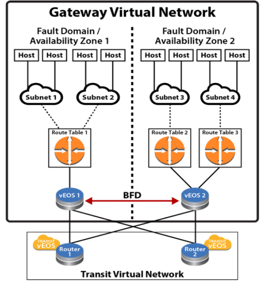
In the diagram above, a virtual network is a collection of resources that are in the same cloud region. Within this virtual network, the resources, including veos routers, deploy into two cloud high availability zones (Availability Zones for AWS and Fault Domain for Azure) for fault tolerance reasons.
Within each availability zone, the hosts/VMs and veos interfaces are connected to their corresponding subnets when the network is operating normally. Each subnet associates to a route table within the cloud infrastructure. Static routes are configured in the cloud route tables so the traffic from the hosts/VMs are routed to veos routers in the corresponding availability zone as gateway or next-hop to reach certain destinations. For example, configure a default route (0.0.0.0/0) in the cloud route table with the next-hop as veos router's cloud interface ID or IP (varies depending on the cloud). The routing policy or protocol, such as BGP, on the veos routers, are user configurable based on user's network design.
The two veos routers in the diagram above are configured with the Cloud HA feature as HA peers. The Cloud HA on the veos routers would establish a BFD peering session between the two devices through ethernet or tunnel interfaces.
When BFD connectivity loss is detected by the active veos router, the existing routes in the backup route table in the cloud would be updated through cloud-specific API to use the active veos router as the next-hop. For example, if veos 2 detected BFD connectivity loss with its peer, veos 2 would update the routes in Route Table 1 so traffic from hosts in Subnet 1 and Subnet 2 for veos 1 would be forwarded to next-hop ID or IP owned by veos 2. Traffic from the hosts in availability zone 1 would first be forwarded to the corresponding subnet gateways in the cloud. After that, the subnet gateways in the cloud would forward the traffic toward the new next-hop interface ID or IP that exist on veos 2. When veos 2 received the traffic, it would forward the traffic on according to its routing table.
What about traffic going toward the hosts in availability zone 1 while connectivity to veos 1 is down? When connectivity to veos 1 is down, hosts behind Subnet 1 and Subnet 2 become unreachable to the other part of the network (routes being withdrawn by routing protocols like BGP). Since Subnet 1 and Subnet 2 are not directly connected to veos 2, a routing strategy for the two subnets as "backup" on veos 2 is to be considered as part of your network design. A typical design would be to use static routes for the subnets connected to the peer veos router and point them toward the cloud subnet gateways of the active veos router (for example, static route for peer subnet 10.1.1.0/24 would be configured on the active veos router as ip route10.1.1.0/24 10.2.1.1 255 where 10.2.1.1 is the gateway/next-hop for one of the ethernet interfaces) with a high administrative distance value (least preferred). The static routes would be redistributed or advertised when the original routes with better administrative distance are withdrawn or removed by dynamic routing protocol (such as BGP).
When BFD peering session is restored to UP state upon recovery, each active veos router would restore its locally controlled route table entries (per user configuration) to point to itself as primary gateway again.
Configuring the Cloud Proxy
Optional proxies can be configured if used in a deployment. The configuration is applicable for any cloud type. All web traffic for the underlying restful APIs for the Cloud provider SDK will use the configured proxies. Multiple proxies can be configured but only one can be used at any given time from the Cloud High-Availability configuration.
router(config)#
router(config)#cloud proxy test
router(config-cloud-proxy-test)#
The following example configures the cloud proxy IP, port, username, and password for HTTP.
router(config)#
router(config)#cloud proxy test
router(config-cloud-proxy-test)#http 1.2.3.4 1234 username test password 7 075E731F1A
router(config-cloud-proxy-test)#
Configuring the Cloud Provider
Cloud Configuration
To have access to the cloud services, the cloudeos router must be provided with credentials. Additionally, a proxy may be configured for the connection to the cloud services.
AWS Specific Cloud
Complete the following tasks to configure AWS-specific Cloud services.
- Configure Credentials
- Access to AWS Specific Cloud API Server
- If cloudeos router is associated with a public IP address, no special configuration is required.
- If cloudeos router is not associated with an public IP address, either use AWS Private Link or Proxy configuration
Configure Credentials
In the AWS Specific Cloud configuration, a region must be specified. It is recommended to authorize the cloudeos router by assigning it an IAM role, but an explicit credential can also be specified.
- IAM Role Configuration - No credentials. See Cloud Provider Helpful Tips for additional information.
- Explicit Credential Configuration
AWS Specific Cloud IAM Role Configuration
The IAM role should be configured on the AWS Specific as shown below. This is the recommended configuration.
- "Trust Relationships" has "ec2.amazonaws.com" as trusted entities.
- "Policy" with "Permissions" for the network related EC2 actions.
{
    "Version": "2012-10-17",
    "Statement": [
        {
            "Effect": "Allow",
            "Action": [
                "ec2:AssociateRouteTable",
                "ec2:CreateRoute",
                "ec2:CreateRouteTable",
                "ec2:DeleteRoute",
                "ec2:DeleteRouteTable",
                "ec2:DescribeRouteTables",
                "ec2:DescribeVpcs",
                "ec2:ReplaceRoute",
                "ec2:DisassociateRouteTable",
                "ec2:ReplaceRouteTableAssociation",
                "ec2:DescribeNetworkInterfaces",
                "ec2:DescribeInstances",
                "ec2:DescribeSubnets"
            ],
            "Resource": "*"
        }
    ]
}
This is applicable only when running in AWS cloud environment and configures various aspects of Cloud HA feature to interact with AWS web services.
Note: Configure The access-key-id and secret access-key commands or omit the configuration of both. If omitted, the Cloud HA Agent attempts to use AWS IAM role for security tokens to access and control AWS route tables. Verify the correct configuration of the IAM role for the cloudeos router Virtual Machine( VM ) on the AWS Cloud. Refer to AWS documentation to configure the IAM role.
router(config)#
router(config)#cloud provider aws
router(config-cloud-aws)#access-key 0 ATPAILIL5E982IPT7P3R
router(config-cloud-aws)#secret access-key 0 M0RRUtAA8I8wYxJB8
router(config-cloud-aws)#region us-west-1
router(config-cloud-aws)#proxy test
Configure the backup-gateway, primary-gateway, Route Table ID(rtb) and local interface for AWS.
Specify the Route Table ID for the AWS backup-gateway and primary gateway, then the destination selects the individual route within the route table to control. The local-cloud-interface then points to the interface ID eni-867caa86 (from AWS perspective) of the router that the traffic should be directed.
router(config)#cloud high-availability
router(config-cloud-ha)#peer veos2
router(config-cloud-ha-peer-veos2)#aws
router(config-cloud-ha-peer-veos2-aws)#backup-gateway rtb-40b72d24
0.0.0.0/0 local-cloud-interface eni-867caa86
router(config-cloud-ha-peer-veos2-aws)#primary-gateway rtb-2843124c
0.0.0.0/0 local-cloud-interface eni-867caa86
Explicit Credential Configuration
The explicit credential should be configured as shown below.
router(config)#cloud provider aws
router(config-cloud-aws)#region us-west-1
router(config-cloud-aws)#access-key 0 MYEXAMPLESECRETKEY
router(config-cloud-aws)#secret access-key 0 MYEXAMPLESECRETKEY
router(config-cloud-aws)#exit
router(config-cloud)#exit
Azure
- SDK Auth Credentials
To generate SDK Auth Credentials, use the sdk authentication credential-file flash:startup-config command in the config-cloud-azure configuration mode.
router(config)#cloud provider azure
router(config-cloud-azure)#sdk authentication credential-file
flash:startup-config
- Active Directory Credentials
The following example places the router into the config-cloud-azure configuration mode and sets the active directory credentials.
router(config)#cloud provider azure
router(config-cloud-azure)#active-directory credential
email subscription-id ef16892c-aa46-4aba-ae9a-d4fhsb1c612c
Configuring BFD
router(config)#cloud high-availability
router(config-cloud-ha)#peer veos2
router(config-cloud-ha-peer-veos2)#bfd source-interface tunnel 2 single-hop
Configuring the Recovery Time
The recovery wait-time command in the cloud-ha configuration sub-mode configures the amount of time to take back control of local route tables after failure recovery. The following example shows the wait time is configured to 90 seconds.
router(config-cloud-ha-peer-veos2)#recovery wait-time 90
Cloud Provider Helpful Tips
The following are needed for Cloud High Availability but are not part of the WAN configuration on the WAN router. These may change or can be another way to achieve the same effect without changing the WAN router.
AWS VPN Specific Cloud PrivateLink
AWS VPN Specific Cloud PrivateLink allows a private (no public IP address) WAN instance to access services offered by AWS (without using proxy).
The interface VPC endpoints enables a private WAN instance to connect to AWS VPN Specific Cloud PrivateLink.
To configure Interface VPC Endpoints:
- Open the Amazon VPC console and choose Endpoints in the navigation panel.
- Select Create Endpoint.
- Choose the AWS Services and select service name com.amazonaws.<your-region>.ec2.
- Choose the VPC and the subnets in each availability zone for the Interface VPC endpoints.
- Enable private DNS name and set security group accordingly.
- Select Create Endpoint.
Once the Endpoint(s) is created, the EC2 API IP associated with the domain-name will be updated to the endpoint IP.
Additional interface VPC endpoints information can be found at: https://docs.aws.amazon.com/AmazonVPC/latest/UserGuide/vpce-interface.html
Configuring Cloud High Availability
To enable the Cloud HA and its parameters, use the following configurations.
Enable Cloud High Availability
The cloud high-availability command places the WAN in the cloud-ha configuration mode. This example enables cloud high-availability and configures the peer veos2.
router(config)#cloud high-availability
router(config-cloud-ha)#no shutdown
router(config-cloud-ha)#peer veos2
router(config-cloud-ha-peer-veos2)#
AWS Specific for High Availability
This is applicable only when running in AWS cloud environment and configures various aspects of Cloud HA feature to interact with AWS web services.
Note: The access-key-id and secret access-key commands are either both configured or both are omitted. If omitted, the Cloud HA Agent will try to use AWS IAM role for security tokens to access and control AWS route tables. Verify the IAM role for the WAN router Virtual Machine( VM ) is configured properly on the AWS cloud. Refer to AWS documentation to configure IAM role.
router(config)#
router(config)#cloud provider aws
router(config-cloud-aws)#access-key 0 ATPAILIL5E982IPT7P3R
router(config-cloud-aws)#secret access-key 0 M0RRUtAA8I8wYxJB8
router(config-cloud-aws)#region us-west-1
router(config-cloud-aws)#proxy test
Configure the backup-gateway, primary-gateway, Route Table ID(rtb) and local interface for AWS.
The Route Table ID specifies for AWS the backup-gateway and primary gateway, then the destination selects the individual route within the route table to control. The local-cloud-interface then points to the interface ID eni-867caa86 (from AWS perspective) of the veos router that the traffic should be directed.
AWS
router(config)#cloud high-availability
router(config-cloud-ha)#peer veos2
router(config-cloud-ha-peer-veos2)#aws
router(config-cloud-ha-peer-veos2-aws)#backup-gateway rtb-40b72d24
0.0.0.0/0 local-cloud-interface eni-867caa86
router(config-cloud-ha-peer-veos2-aws)#primary-gateway rtb-2843124c
0.0.0.0/0 local-cloud-interface eni-867caa86
Azure Specific for High Availability
Azure
- SDK Auth Credentials
To generate SDK Auth Credentials, use the sdk authentication credential-file flash:startup-config command in the config-cloud-azure configuration mode.
router(config)#cloud provider azure
router(config-cloud-azure)# sdk authentication credential-file
flash:startup-config
- Active Directory Credentials
The following example places the veos router into the config-cloud-azure configuration mode and sets the active directory credentials.
router(config)#cloud provider azure
router(config-cloud-azure)#active-directory credential
email subscription-id ef16892c-aa46-4aba-ae9a-d4fhsb1c612c
Configure the backup-gateway, primary-gateway, Route Table ID (rtb), resource-group and next-hop for Azure
The resource group specified is the one which contains the route table referenced beneath it. The nextHopIp is the IP of the veos router interface that traffic should be directed.
Azure
router(config)#cloud high-availability
router(config-cloud-ha)#peer veos2
router(config-cloud-ha-peer-veos2)#azure
router(config-cloud-ha-peer-veos2-azure)#backup-gateway Subnet-2-veos-RouteTable 0.0.0.0/0 10.1.1.4 resource-group my_resource_group_64f86970ffe24ab
GCP Specific for High Availability
In GCP specific cloud configuration, you must specify a Project. The GCP cloud uses either the Default Credentials, or a Service Account mode for authorization.
- Default Credentials: Cloud HA uses the Application Default Credentials for authorization and no configuration is required. Setup a GCP instance with a service account with the requisite permissions. For more information on creating an instance with a service account or changing the service account of an existing instance, refer: https://cloud.google.com/compute/docs/access/create-enable-service-accounts-for-instances
- Service Account: Specify a service account file. For more information on creating a service account file, refer:https://cloud.google.com/iam/docs/creating-managing-service-account-keys#creating_service_account_keys
{
  "type": "service_account",
  "project_id": "project-id",
  "private_key_id": "key-id",
  "private_key": "-----BEGIN PRIVATE KEY-----\nprivate-key\n-----END PRIVATE KEY-----\n",
  "client_email": "service-account-email",
  "client_id": "client-id",
  "auth_uri": "https://accounts.google.com/o/oauth2/auth",
  "token_uri": "https://accounts.google.com/o/oauth2/token",
  "auth_provider_x509_cert_url": "https://www.googleapis.com/oauth2/v1/certs",
  "client_x509_cert_url": "https://www.googleapis.com/robot/v1/metadata/x509/service-account-email"
}
For Default Credentials or Service Account authorization model, the role associated with the cloudeos instance/service account must have the following permissions:
- compute.networks.get
- compute.networks.updatePolicy
- compute.projects.get
- compute.routes.create
- compute.routes.delete
- compute.routes.get
- compute.routes.list
Example
- Cloud HA GCP configuration example.
cloudeos(config)#
cloudeos(config)#cloud provider gcp
cloudeos(config-cloud-gcp)#project gcp-project-name
cloudeos(config-cloud-gcp)#service-account file flash:.gcp_service_account.json
cloudeos(config-cloud-gcp)#proxy test
Specify a destination prefix for Cloud HA routes on GCP to select the individual routes that we wish to control. Since route table is not present in GCP, you can specify an optional tag for each route to simulate the route table.
cloudeos(config)#cloud high-availability
cloudeos(config-cloud-ha)#peer veos2
cloudeos(config-cloud-ha-peer-veos2)#gcp
cloudeos(config-cloud-ha-peer-veos2-gcp)#backup-gateway 0.0.0.0/0 tag tag2
cloudeos(config-cloud-ha-peer-veos2-gcp)#primary-gateway 0.0.0.0/0 tag tag1
Limitations
- For Cloud HA on AWS/Azure, pre-create the HA routes before configuring these routes on a cloudeos instance. For GCP, the HA routes are created automatically by Cloud HA, and thus no need to pre-create any HA routes to avoid route conflicts.
- For GCP, though the HA routes are automatically created by Cloud HA, they do not get deleted automatically from GCP when removed from the Cloud HA configuration from cloudeos instance. Hence, you need to delete these routes from GCP manually.
- Cloud HA on GCP allows adding routes only in the VPC network corresponding to the first interface (nic0) of the cloudeos instance.
- Since routes in GCP are added at a per VPC level, specify the tags used to simulate route tables when adding a Cloud HA route using the primary-gateway / backup-gateway command. Use the same tag to apply manually on the Cloud HA routes to a subset of the instances in the VPC network.
cloudeos HA GCP provider commands
cloud provider
           gcp
The cloud provider gcp command places the switch in cloud-provider-gcp configuration mode, and allows you to configure cloud provider gcp command parameters. The exit command returns the router to global configuration mode.
Global Configuration
Command Syntax
cloud provider gcp
- These commands places the cloud provider for GCP into the configuration mode.
router#config router(config)#cloud provider gcp router(config-cloud-gcp)#
- The exit command returns to the global configuration mode.
router(config-cloud-gcp)#exit router(config)#
project
The project command specifies the GCP project name. The no project command removes the configuration from the router running-config.
Global Cloud Provider GCP Configuration
Command Syntax
project name
no project name
- name Specifies the selected GCP project name.
- These commands configures the GCP project.
router(config)#cloud provider gcp router(config-cloud-gcp)#project test-project
- The no project command removes the GCP project.
router(config)#cloud provider gcp router(config-cloud-gcp)#no project test-project
service-account
The service-account specifies the service account file when using the Service Account authorization model. The no service-account command removes the configuration from the router running-config.
Global Cloud Provider GCP Configuration
Command Syntax
service-account file sa-file
no service-account file sa-file
- sa-file Specifies the path to the service account file.
- These commands configures the Service Account file used.
router(config)#cloud provider gcp router(config-cloud-gcp)#service-account file flash:.gcp_service_account.json router(config-cloud-gcp)#
- The no service-account command removes the Service Account file configuration.
router(config)#cloud provider gcp router(config-cloud-gcp)#no service-account file flash:.gcp_service_account.json router(config-cloud-gcp)#
primary-gateway
The primary-gateway command in the Cloud High Availability Configuration mode adds a primary high availability route for GCP. The no primary-gateway command removes the route configuration from the WAN running-config.
Cloud HA GCP Configuration Submode
Command Syntax
primary-gateway dest-prefix [tag rt-tag]
no primary-gateway dest-prefix [tag rt-tag]
- dest-prefix Specifies the destination IP prefix.
- rt-tag Specifies the route tag.
- These commands configures a primary high availability route.
router(config)#cloud high-availability router(config-cloud-ha)#peer veos2 router(config-cloud-ha-peer-veos2)#gcp router(config-cloud-ha-peer-veos2-azure)#primary-gateway 10.1.0.0/16 tag tag1
- The no primary-gateway command removes the primary high availability route configuration.
router(config)#cloud high-availability router(config-cloud-ha)#peer veos2 router(config-cloud-ha-peer-veos2)#gcp router(config-cloud-ha-peer-veos2-azure)#no primary-gateway 10.1.0.0/16 tag tag1
backup-gateway
The backup-gateway command in the cloud-ha submode adds a backup high availability route for GCP. The no backup-gateway command removes the route configuration from the WAN running-config.
Cloud HA GCP Configuration Submode
Command Syntax
backup-gateway dest-prefix [tag rt-tag]
no backup-gateway dest-prefix [tag rt-tag]
- dest-prefix Specifies the destination IP prefix.
- rt-tag Specifies the route tag.
- These commands configures a backup high availability route.
router(config)#cloud high-availability router(config-cloud-ha)#peer veos2 router(config-cloud-ha-peer-veos2)#gcp router(config-cloud-ha-peer-veos2-azure)#backup-gateway 10.1.0.0/16 tag tag2
- The no primary-gateway command removes the backup high availability route configuration.
router(config)#cloud high-availability router(config-cloud-ha)#peer veos2 router(config-cloud-ha-peer-veos2)#gcp router(config-cloud-ha-peer-veos2-azure)#no backup-gateway 10.1.0.0/16 tag tag2
show
           cloud high-availability routes
The show cloud high-availability routes command displays the configured local or peer route table, destination IP address and local Next Hop Interface.
EXEC
Command Syntax
show cloud high-availability routes
- The show cloud high-availability routes command displays high availability routes information.
router(config)#show cloud high-availability routes Peer Route Type Destination Tag ------ ------------ -------------- ------ peer primary 21.2.3.14/24 peer primary 1.2.3.4/21 tag1 peer backup 1.2.3.4/21 tag2 peer backup 11.2.3.4/21 az1
show cloud
           provider gcp
The show cloud provider gcp command displays cloud provider information for the GCP platform.
EXEC
Command Syntax
show cloud provider gcp
- The show cloud provider gcp command displays the GCP cloud configuration for Default Credentials authorization model. .
router(config)#show cloud provider gcp
Project: project-123
Authentication mode: default credentials
Service account file:
Proxy: myProxyName
- The following example displays the GCP cloud configuration for Service Account authorization model.
router(config)#show cloud provider gcp
Project: project-123
Authentication mode: service account
Service account file: flash:.gcp_service_account.json
Proxy: myProxyName
Full Configurations
AWS VPN Specific Cloud Full Configuration
The following AWS configuration is valid for use with the IAM role.
cloud provider aws
 region us-west-1
!
cloud high-availability
 no shutdown
 !
 peer veos2
  aws
   backup-gateway  rtb-40b72d24 0.0.0.0/0 local-cloud-interface eni-26cb1d27
   backup-gateway  rtb-17b32973 0.0.0.0/0 local-cloud-interface eni-1589e714
   backup-gateway  rtb-54503330 0.0.0.0/0 local-cloud-interface eni-56cf1957
   primary-gateway rtb-a4be24c0 0.0.0.0/0 local-cloud-interface eni-26cb1d27
   primary-gateway rtb-40b72d24 0.0.0.0/0 local-cloud-interface eni-56cf1957
   primary-gateway rtb-63b02a07 0.0.0.0/0 local-cloud-interface eni-1589e714
  peer address 10.2.201.149
  recovery wait-time 5
  bfd source-interface Ethernet1
!
Azure Full Configuration
The following Azure configuration is valid for the MSI.
cloud high-availability
 no shutdown
 !
 peer veos2
 azure
  backup-gateway Subnet-2-veos-RouteTable 0.0.0.0/0 10.1.2.4 resource-group CloudHaAzure
  backup-gateway Subnet-2-veos-RouteTable 10.1.0.0/16 10.1.2.4 resource-group CloudHaAzure
  backup-gateway Subnet-3-veos-RouteTable 10.1.0.0/16 10.1.3.4 resource-group CloudHaAzure
  backup-gateway Subnet-3-veos-RouteTable 0.0.0.0/0 10.1.3.4 resource-group CloudHaAzure
  primary-gateway Subnet-1-veos-RouteTable 10.1.0.0/16 10.1.1.4 resource-group CloudHaAzure
  primary-gateway Subnet-1-veos-RouteTable 0.0.0.0/0 10.1.1.4 resource-group CloudHaAzure

 peer address 10.1.0.5
 recovery wait-time 10
 bfd source-interface Ethernet1
Cloud HA GCP Full Configuration
- The following GCP configuration uses default credentials.
cloudeos - 1
cloud provider gcp
 project gcp-project-name
!
cloud high-availability
 no shutdown
 !
 peer cloudeos2
  gcp
   backup-gateway 0.0.0.0/0 tag tag1
   backup-gateway 0.0.0.0/0 tag tag2
   primary-gateway 0.0.0.0/0 tag tag3
   primary-gateway 0.0.0.0/0 tag tag4
  peer address 10.3.0.59
  recovery wait-time 5
  bfd source-interface Ethernet1
!
- cloudeos - 2
cloud provider gcp
 project gcp-project-name
!
cloud high-availability
 no shutdown
 !
 peer cloudeos1
  gcp
   backup-gateway 0.0.0.0/0 tag tag3
   backup-gateway 0.0.0.0/0 tag tag4
   primary-gateway 0.0.0.0/0 tag tag1
   primary-gateway 0.0.0.0/0 tag tag2
  peer address 10.3.0.59
  recovery wait-time 5
  bfd source-interface Ethernet1
!
General Troubleshooting Tips
If the Cloud HA feature doesn't work as expected, follow these tips for debugging.
- Network Connectivity and DNS - Ensure network connectivity and proper DNS server setup for this feature to function.
- Proxy and IAM Role (AWS) - When using a proxy and IAM role within AWS, ensure that HTTP traffic (TCP port 80) is not proxied. This allows cloudeos router instances to retrieve temporary security credentials.
- BFD Source Interface - Use a corresponding BFD source interface on the peer cloudeos router instance. This ensures that BFD traffic ingress and egress utilize the same interface on each instance.
- AWS IAM Role Issue: If the IAM role doesn't work within an AWS Cloud environment, temporarily use the access key ID and secret access key with sufficient permissions. This confirms the rest of the Cloud HA configuration while you debug the IAM role policy.
Caveats and Limitations
- This feature was introduced in EOS release 4.20.5F which uses /mnt/flash/cloud_ha_config.json file for Cloud HA configuration without any CLI support. Starting from release 4.20.5.A1 onwards, Cloud HA feature supports CLI based configuration only. Deployments using JSON based configurations are not supported and will not work when the image is upgraded or downgraded. To upgrade image, the administrator must configure Cloud HA feature manually by converting the JSON configuration to equivalent CLI configuration. Downgrading will work as long as the older JSON file is still present in /mnt/flash directory.
- Only a single resource-group is supported across all routing entries for Azure under Cloud specific config HA configuration.
- The Cloud HA feature currently supports only a single peer.
- The AWS IAM role or Azure MSI needs to be configured properly using cloud provider's management tools and should give sufficient permissions to WAN instance to access and update route table entries.
- The WAN instance should have connectivity to the cloud provider's web services. The access can also be via proxy or using feature like AWS private-link.
- The recovery wait-time should not be configured less than 10 seconds to avoid unnecessary route flapping when experiencing periodic instabilities.
- The Cloud HA feature completely validates all the provided cloud configuration to make sure it is consistent and has all required permissions. However, the administrator should not change the provider's network configuration afterwards to avoid any issues during fail-over.
- When there are BFD connectivity issues between the two WAN peers, each instance will take over the other's traffic. This cross traffic forwarding on provider's network should not have any adverse affect and still work as active-active even though both of the instance will report as fail-over. After the network connectivity is resolved, the traffic pattern reverts to the normal active-active mode.
- The user can adjust the BFD specific parameters for the session used by Cloud HA feature using normal BFD commands such as multiplier, tx/rx intervals, etc. The Cloud HA fail-over and traffic takeover time is directly correlated with BFD failure detection time. However, when using an overly aggressive BFD, the failover time may incur higher overhead as well may result in greater instability during traffic bursts. Arista recommends using the use default BFD interval which is currently 300 msec with a multiplier of 3.
- The bfd source-interface used in Cloud HA configuration should not belong and/or routable via the route-tables controlled by the WAN router instance itself to avoid traffic looping issues.
- If the Cloud HA is in an invalid configuration state due to erroneous/mismatched configuration in the provider's cloud, the administrator has to force update the Cloud HA configuration (for example, by shut/no shut under Cloud HA mode) after updating the provider's cloud configuration. In other words, by itself, the Cloud HA feature will not retry the back-end configuration check if it is found to be invalid at the time of configuration.
Cloud High Availability Commands
Global
Cloud Provider Commands
Global
Cloud Proxy Commands
Global
InterfaceShow Commands
EXEC
Cloud High Availability CLIs
The Cloud High Availability CLIs are divided into three separate configuration modes:
- Cloud Proxy - For proxy related configuration such as http and https.
- Cloud Provider - For cloud provider specific configuration such as region, credential, and proxy name.
- Cloud High-Availability - For configurations such as route, next-hop, BFD source interface, and peer.
access-key-id
The cloud provider AWS command places the cloudeos router in Cloud Provider AWS Configuration mode. This configuration mode allows user to configure cloud provider aws access-key-id command parameters. The no access-key-id command removes the configuration from the cloudeos router running-config. The exit command returns the cloudeos router to global configuration mode.
Command mode
Cloud Provider AWS Configuration
Command Syntax
access-key-id Password_Type
no access-key-id Password_Type
Parameters
Password_Type
- 0 access-key-id The password is a clear-text string. Equivalent to no parameter.
-
7 encrypted_key The password is an encrypted string.
- Text
Example
The following example configures the AWS access key to encrypted.
router(config)#cloud provider aws
router(config-cloud-aws)#access-key 0 565656 test
Example
The following example removes the AWS access key and returns the veos to Global configuration mode.
router(config-cloud-aws)#access-key 0 565656 test
router(config-cloud-aws)#no access-key 0 565656 test
router(config)#
Example
The following example returns the veos to Global configuration mode.
router(config-cloud-aws)#access-key 0 565656 test
router(config-cloud-aws)#exit
router(config)#
active-directory credential email subscription-id (cloudeos router-Azure)
The active-directory credential email subscription-id command in the Cloud Provider Azure Configuration mode configures Azure's cloud provider azure active-directory credential parameters. The no active-directory command removes the configuration from the cloudeos router running-config. The exit command returns the cloudeos router to global configuration mode.
Command mode
Cloud Provider Azure Configuration
Command Syntax
active-directory credential email subscription-id ID
no active-directory credential email subscription-id
Parameters
- ID Defines the active directory subscription ID.
Example
The following example places the cloud provider for Azure into the configuration mode.
router(config)#cloud provider azure
router(config-cloud-azure)#active-directory credential email subscription-id
Example
router(config)#cloud provider azure
router(config-cloud-azure)#active-directory credential email subscription-id
azure
The azure command in the Cloud High Availability Peer Configuration mode allows the user to configure cloud high-availability peer related parameters. The exitcommand returns the cloudeos router to the to the cloud-ha-peer configuration mode.
Command mode
Global Cloud High Availability Peer Configuration Submode
Command Syntax
azure
Example
The following example configures the peer related information for Azure.
router(config)#cloud high-availability
router(config-cloud-ha)#peer p
router(config-cloud-ha-peer-veos2)#azure
router(config-cloud-ha-peer-veos2-azure)#
Example
The following example returns the cloudeos router to the cloud-ha configuration mode.
router(config-cloud-ha-peer-veos2-azure)#exit
router(config-cloud-ha-peer-veos2)#
backup-gateway
The cloud high-availability command in the Cloud High Availability Configuration mode assigns the backup gateway parameters for the Azure high availability peered cloud. The no backup-gateway command removes the configuration from the cloudeos router running-config. The exit command returns the cloudeos router to global configuration mode.
Command mode
Cloud HA Azure Configuration
Command Syntax
backup-gateway [Azure Rt_Info] resource-group [Name]
no backup-gateway
Parameters
- Azure Rt_Info
- azure-rt-name The azure route name.
- dest-ip-address/mask The destination IP address.
- local-ip-address The local IP address.
- resource-group
- Name Azure resource group name.
Example
The following example configures the parameters for the Azure high availability peered cloud.
router(config)#cloud high-availability
router(config-cloud-ha)#peer veos2
router(config-cloud-ha-peer-veos2)#azure
router(config-cloud-ha-peer-veos2-azure)#backup-gateway Rt1 10.10.1.1/10 1.1.1.1 resource-group test
Example
The following example removes the backup-gateway parameters for the Azure high availability peered cloud.
router(config-cloud-ha-peer-veos2-azure)#no backup-gateway Rt1 10.10.1.1/10
router(config-cloud-ha-peer-veos2-azure)#
bfd source-interface (cloudeos router)
The bfd source-interface command in the Cloud High Availability Configuration mode configures BFD source interface parameters for the high availability peer. The no bfd source-interface command removed the BFD configurations from the cloudeos router running-config.
Command mode
Global Cloud HA peer configuration mode
Command Syntax
bfd source-interface [Interface_Type] single-hop
no bfd source-interface
Parameters
- Interface_Type
- Ethernet Ethernet Port number <1-4>.
- Loopback Loopback interface <0-1000>.
- Tunnel Tunnel interface <0-255>.
- Single-hop Single hop BFD . Default is multi-hop.
Example
The following example configures Ethernet 1 as the source interface for BFD and multi-hop set as the default .
router(config)#cloud high-availability
router(config-cloud-ha)#peer veos2
router(config-cloud-ha-peer-veos2)#bfd source-interface ethernet 1
Example
The following example configures Tunnel 2 as a single hop the source interface for BFD.
router(config)#cloud high-availability
router(config-cloud-ha)#peer veos2
router(config-cloud-ha-peer-veos2)#bfd source-interface tunnel 2 single-hop
Example
The following example removes the BFD configuration.
router(config-cloud-ha-peer-veos2)#no bfd source-interface
cloud high-availability peer
Configures one peer at a time into high availability.
Command mode
Global Cloud HA configuration submode
Command Syntax
config-cloud-ha-peer <peer name>
Example
The following example configures the peer and places it in the cloud high availability configuration mode.
router(config)#cloud high-availability peer peer1
 router(config-cloud-ha-peer-peer1)#
cloud high-availability shutdown
The shutdown command in the Cloud High Availability Configuration mode disables High Availability for virtual EOS instances running in the cloud environment.
Command mode
Cloud High Availability Configuration
Command Syntax
shutdown
Example
The following example configures the peer and places it in the cloud high availability configuration mode.
router(config)#cloud high-availability
router(config-cloud-ha)#shutdown
cloud provider aws (cloudeos router)
The cloud provider aws command places the cloudeos router in Cloud Provider AWS Configuration mode. This configuration mode allows user to configure cloud provider aws command parameters. The exit command returns the cloudeos router to global configuration mode.
Command mode
Global Configuration
Command Syntax
cloud provider aws
Example
The following example places the cloud provider for AWS into the configuration mode.
router#config
router(config)#cloud provider aws
router(config-cloud-aws)#
Example
The following example returns to the global configuration mode.
router(config-cloud-aws)#exit
router(config)#
cloud provider azure (cloudeos router)
The cloud provider azure command places the cloudeos router in cloud-provider-azure configuration mode. This configuration mode allows user to configure cloud provider azurecommand parameters. The exit command returns the cloudeos router to global configuration mode.
Command mode
Global Configuration
Command Syntax
cloud provider azure
Example
router(config)#cloud provider azure
router(config-cloud-azure)#
cloud proxy (cloudeos router)
The cloud proxy command places the cloudeos router in the Cloud Proxy Configuration mode. This configuration mode allows user to configure the cloud proxy command parameters. The no cloud proxy command disables the named proxy and returns the cloudeos router to global configuration mode.
Command mode
Global Configuration
Command Syntax
cloud proxy proxy_name
no cloud proxy proxy_name
Parameters
proxy_name The proxy name to configure.Example
The following example configures the cloud proxy configuration setting for "test".
router(config)#
router(config)#cloud proxy test
router(config-cloud-proxy-test)#
Example
This command disables the cloud proxy named "test" and returns the veos to global configuration mode.
router(config-cloud-proxy-test)# no cloud proxy test
router(config)#
http (cloudeos router)
The http command in the cloud-proxy configuration submode configures the IP, port, username, and password parameters. The no http command removes the configured cloud proxy information for HTTP from the running-config and returns the cloudeos router to the global configuration mode.
Command mode
Global Cloud Proxy Configuration
Command Syntax
http [proxy_IP_port] [username] [password]
no http [proxy_IP_port] [username] [password]
Parameters
- proxy_IP_port Port number to be used for the HTTP server. Options include:
- proxy-ip IP address used for the HTTPs proxy. Dotted decimal location.
- proxy_port HTTPS proxy port. Value ranges from 1 to 65535.
- username Name string.
- password Password string.
- 0 cleartext-passwd Indicates the cleartext password is in clear text. Equivalent to the no parameter case.
- 7 encrypted_passwd Indicates encrypted password is md5 encrypted.
Example
The following example configures the cloud proxy IP, port and username and password for HTTP.
router(config)#cloud proxy test
router(config-cloud-proxy-test)# http 1.2.3.4 1234 username test password 7 075E731F1A
router(config-cloud-proxy-test)#
Example
The following example removes the configured cloud proxy information for HTTP from the running-config.
router(config-cloud-proxy-test)# no http 1.2.3.4 1234 username test password 7 075E731F1A
router(config-cloud-proxy-test)#
https (cloudeos router)
The https command in the command in the cloud-proxy configuration submode configures the IP, port, username and password parameters. The no https command removes the configured cloud proxy information for HTTPS from the running-config and returns the cloudeos router to global configuration mode.
Command mode
Global Cloud Proxy Configuration
Command Syntax
https [[proxy_IP_port] [username]] [password]
no https [[proxy_IP_port] [username]] [password]
Parameters
- proxy_IP_port Port number to be used for the HTTP server. Options include:
- proxy-ip IP address used for the HTTPs proxy. Dotted decimal location.
- proxy_port HTTPS proxy port. Value ranges from 1 to 65535.
- username Name string.
- password Password string.
- 0 cleartext-passwd Indicates the cleartext password is in clear text. Equivalent to the no parameter case.
- 7 encrypted_passwd Indicates encrypted password is md5 encrypted.
Example
The following example configures the cloud proxy IP and port for HTTPS.
router(config)#
router(config)#cloud proxy test
router(config-cloud-proxy-test)#https 10.3.255.155 8888
Example
The following example removes the configured cloud proxy HTTPS information from the running-config.
router(config-cloud-proxy-test)#no https 10.3.255.155 8888
router(config-cloud-proxy-test)#
peer (cloudeos router)
The peer command in the cloud-ha configuration mode identifies which peer to configure by name. The peer command in the cloud-ha configuration submode configures the cloud high-availability resource group peer related parameters. The no peer command removes the configuration from the cloudeos router running-config. The exitcommand returns the cloudeos router to the cloud-ha configuration mode.
Command mode
Cloud High Availability Configuration
Cloud High Availability Configuration Submode
Command Syntax
peer ip-address
no peer ip-address
Parameters
- IP-address The peer IP address.
Example
The following example configures the cloud high availability peer.
router(config-cloud-ha)#peer veos2
router(config-cloud-ha-peer-veos2)#
Example
The following example configures the peer IP address as 10.10.10.149.
router(config)#cloud high-availability
router(config-cloud-ha)#peer veos2
router(config-cloud-ha-peer-veos2)#peer 10.10.10.149
Example
The following example removes the peer IP address from the veos running-config.
router(config)#cloud high-availability
router(config-cloud-ha)#peer veos2
router(config-cloud-ha-peer-veos2)#no peer 10.10.10.149
primary gateway (cloudeos router - Azure)
The primary-gateway command in the cloud-ha submode assigns the primary gateway parameters for the Azure high availability peered cloud. The no primary-gateway command removes the configuration from the cloudeos router running-config.
Command mode
Cloud HA Azure Configuration Submode
Command Syntax
primary-gateway [Azure Rt_Info] resource-group [Name]
no primary-gateway [Azure Rt_Info]
Parameters
- Azure Rt_Info
- azure-rt-name The azure route name.
- dest-ip-address/mask The destination IP address.
- local-ip-address The local IP address.
- resource-group
- Name Azure resource group name.
Example
The following example configures the parameters for the Azure high availability peered cloud.
router(config)#cloud high-availability
router(config-cloud-ha)#peer veos2
router(config-cloud-ha-peer-veos2)#azure
router(config-cloud-ha-peer-veos2-azure)#primary-gateway Rt1 10.10.1.1/10 1.1.1.1 resource-group test
Example
The following example removes the primary-gateway parameters for the Azure high availability peered cloud.
router(config-cloud-ha-peer-veos2-azure)#no primary-gateway Rt1 10.10.1.1/10
router(config-cloud-ha-peer-veos2-azure)#
proxy (cloudeos router)
The proxy command configures the cloud provider aws proxy. The no proxy command removes the configuration from the running-config. The exit command returns the cloudeos router to global configuration mode.
Command mode
Global Cloud AWS Configuration
Command Syntax
proxy <proxy_name>
no proxy <proxy_name>
Parameters
- proxy_name Proxy name to configure.
Example
The following example configures the Azure cloud proxy named "test".
router(config)#cloud provider aws
router(config-cloud-aws)#proxy test
recovery (cloud HA peer)
The recovery wait-time command in the cloud-ha-peer configuration submode defines the amount of time, in seconds, to take control of the local route tables after failure recovery.
Command mode
Cloud HA peer configuration
Command Syntax
recovery wait-time <time-in-secs>
no recovery wait-time <time-in-secs>
Parameters
- time-in-secs The defined amount of time to take back control of local route tables after failure recovery. Default is 30 seconds.
Example
The following example configures the recovery wait time to 90 seconds.
router(config)#cloud ha
router(config-cloud-ha)#p1
router(config-cloud-ha-p1)#recovery wait-time 90
recovery wait-time (cloudeos router)
The recovery wait-time command in the cloud-ha configuration sub-mode allows takes back control of local route tables after failure recovery. The no recovery wait-time command removes the configuration from the cloudeos router running-config. Default is set at 30 seconds.
Command mode
Cloud High Availability peer configuration
Command Syntax
recovery wait-time <period>
no recovery wait-time <period>
default recovery wait-time <period>
Parameters
- period The defined amount of time to take back control of local route tables after failure recovery. Default is 30 seconds.
Example
The following example shows the wait time is configured to 90 seconds.
router(config-cloud-ha-peer1)#recovery wait-time 90
Example
The following example removes the configured the wait time.
router(config-cloud-ha-peer1)#no recovery wait-time
Example
The following example configures the wait time to the default of 30 seconds.
router(config-cloud-ha-peer1)#default recovery wait-time
region (cloudeos router - AWS)
The cloud provider aws command places the cloudeos router in cloud-provider-aws configuration mode. This configuration mode allows user to configure AWS cloud provider region command parameters. The no region command removes the configuration from the cloudeos router running-config. The exit command returns the cloudeos router to global configuration mode.
Command mode
Global Cloud Provider AWS Configuration
Command Syntax
region aws-region
no region aws-region
Parameters
- aws-region Specifies the selected region.
Example
The following example configures the cloud provider AWS region.
router(config)#cloud provider aws
router(config-cloud-aws)#region us-west-1
router(config-cloud-aws)#
Example
The following example removes the cloud provider AWS region.
router(config)#cloud provider aws
router(config-cloud-aws)#no region us-west-1
router(config-cloud-aws)#
secret-access_key (cloudeos router - AWS)
The cloud provider aws command places the cloudeos router in cloud-provider-aws configuration mode. This configuration mode allows user to configure cloud provider aws secret access-key command parameters. The no secret access-key command removes the configuration from the cloudeos router running-config. The exit command returns the cloudeos router to global configuration mode.
Command mode
Global Cloud Provider AWS configuration
Command Syntax
secret access-key password_type
no secret access-key password_type
Parameters
- 0 access-key-id The password is a clear-text string. Equivalent to no parameter.
- 7 encrypted_key The password is an encrypted string.
- Text
Example
The following example configures the AWS secret access key.
router(config)#cloud provider aws
router(config-cloud-aws)#secret access-key 0 565656 test
router(config-cloud-aws)#
Example
The following example removes the secret access key from the cloudeos router running-config.
router(config-cloud-aws)#no secret access-key 0 565656 test
router(config-cloud-aws)#
Example
The following example returns the veos to Global configuration mode.
router(config-cloud-aws)#secret access-key 0 565656 test
router(config-cloud-aws)#exit
router(config)#
show cloud high-availability (cloudeos router)
The show cloud high-availability command displays the high availability configured settings.
Command mode
EXEC
Command Syntax
show cloud high-availability
Example
This command displays details and status of the cloud high-availability configuration.
router#show cloud high-availability
Cloud HA Configuration:
Peer address                      : 10.2.201.149
Source interface                  : Ethernet1
Enabled                           : True
Failover recovery time            : 5
Status                            : valid
State                             : ready
Last failover time                : never
Last recovery time                : never
Last config validation start time : 0:26:08 ago
Last config validation end time   : 0:26:06 ago
Failovers                         : 0
show cloud high-availability routes
The show cloud high-availability routes command displays the configured local or peer route table, destination IP address and local Next Hop Interface.
Command mode
EXEC
Command Syntax
show cloud high-availability routes
Example
The example below displays high availability routes information.
router(config)#show cloud high-availability routes
Peer Route  Type Route  ID Destination Next Hop   Interface
----------- ----------- -------------- ---------- ------------
veos6       primary     rtb-1dc75679   0.0.0.0/0  eni-e61d95e7
veos6       primary     rtb-a29617c6   0.0.0.0/0  eni-69109868
veos6       primary     rtb-acc756c8   0.0.0.0/0  eni-7f1d957e
veos6       backup      rtb-43c65727   0.0.0.0/0  eni-7f1d957e
veos6       backup      rtb-71c65715   0.0.0.0/0  eni-e61d95e7
veos6       backup      rtb-aca223c8   0.0.0.0/0  eni-69109868
show cloud provider aws (cloudeos router - AWS)
The show cloud provider aws command displays cloud provider information for the AWS platform.
Command mode
EXEC
Command Syntax
show cloud provider aws
Example
The following example displays the AWS cloud configuration.
router#show cloud provider aws
Cloud AWS Configuration
Region                   : us-west-1
Access key ID            :
Access secret key        :
Proxy                    : test
Example
The following example displays the primary and backup gateway information for the AWS cloud provider.
router#show run section cloud
cloud provider aws
 us-west-1
 proxy test
!
cloud high-availability
 no shutdown
 !
 peer veos12
  aws
   backup-gateway  rtb-40b72d24 0.0.0.0/0 local-cloud-interface eni-26cb1d27
   backup-gateway  rtb-17b32973 0.0.0.0/0 local-cloud-interface eni-1589e714
   backup-gateway  rtb-54503330 0.0.0.0/0 local-cloud-interface eni-56cf1957
   primary-gateway rtb-a4be24c0 0.0.0.0/0 local-cloud-interface eni-26cb1d27
   primary-gateway rtb-e64b2882 0.0.0.0/0 local-cloud-interface eni-56cf1957
   primary-gateway rtb-63b02a07 0.0.0.0/0 local-cloud-interface eni-1589e714
  peer address 10.2.201.149
 recovery wait-time 5
 bfd source-interface Ethernet1
!
cloud proxy test
 https 10.3.255.155 8888
show cloud provider azure (cloudeos router - Azure)
The show cloud provider azure command displays Azure cloud provider information.
Command mode
EXEC
Command Syntax
show cloud provider azure
Example
The following example displays the Azure cloud configuration.
router#show cloud provider azure
Cloud Azure Configuration:
Active credentials           : SDK authentication credential file
SDK auth credentials file    : flash:
Proxy name                   :
Active directory credentials :
show cloud proxy
The show cloud proxy command displays cloud proxy information.
Command mode
EXEC
Command Syntax
show cloud proxy [<proxy_name>]
Parameters
- proxy_name Identifies the selected proxy by name.
Example
#show cloud proxy [<proxy_name>]
Proxy Name : MyProxyName
Http proxy : 1.2.3.4:8080
Https proxy : 1.2.3.4:4443
Proxy user : proxyuser1
Proxy password : obfuscatedpassword