Cabling the Switch
Grounding the Switch
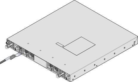
After mounting the switch into the rack, connect the switch to the data center ground.
À la terre et de mise à la terre fils cosses (M4 x 0.7) ne sont pas fournis. Calibre des fils doit satisfaire des exigences de l’installation locale et nationale. Disponible dans le commerce 6 fils AWG est recommandé pour les installations aux États-Unis.
Models with Grounding Pads
Use the grounding pads (Figure 1) to attach the grounding lug before connecting to the data center ground.
.png)
| 1 | Fan Module 1 | 4 | Fan Module 4 | 7 | Grounding |
| 2 | Fan Module 2 | 5 | Power Supply Module 1 | ||
| 3 | Fan Module 3 | 6 | Power Supply Module 2 |
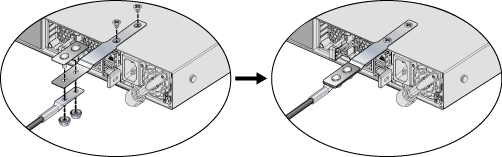
Models without Grounding Pads
For models that do not have grounding pads, use an adapter as shown for the DCS-7050SX3-96YC8 (Figure 2). Assemble an adapter to attach to the chassis (Grounding Adapter Assembly). Attach the grounding lug to the adapter, once it is attached to the chassis.
Grounding Adapter Assembly
Connecting Power Cables
Installation de cet équipement doit être conformes aux codes électriques locaux et nationaux. Si nécessaire, consulter les organismes de réglementation appropriés et des autorités de contrôle pour assurer la conformité.
The switch operates with two installed power supplies. At least one power supply must connect to a power source. Two circuits provide redundancy protection.
Rear Panel displays the location of the power supplies on the rear panel of the switch.
Lire toutes les instructions d'installation avant de brancher le système à la source d'alimentation.
- Non-Redundant Configuration: Connect power to either of the two power supplies.
- Redundant Power Supply Configuration: Connect power to both power supplies.
-
Power down the Switch: Remove all power cords and wires from the power supplies.
Important: This equipment must be grounded. Never defeat the ground conductor.Cet équipement doit être mis à la terre. Ne jamais modifier le conducteur de terre.
Important: This unit requires overcurrent protection.Cet appareil requiert une protection contre les surintensités.
AC Power Supplies
(Figure 4) shows a supported AC power supply. The following AC power supplies are supported.
| PWR-500AC | PWR-1900AC | PWR-2411-AC |
| PWR-1100AC | PWR-745AC | PWR-1011-AC |
Power requirements vary by switch. Refer to Table 3 for information regarding your system as devices are supported only by the specified power supplies. The AC power supply connects to a circuit that provides the required power.
Figure 4 displays an AC power supply, including the power socket on the left side of the module.
The accessory kit provides two IEC-320 power cables for the supported power supply for the device.
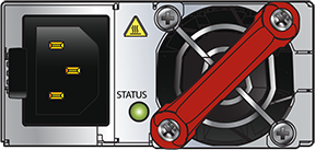
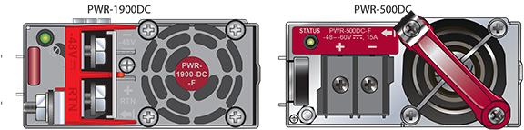
DC Power Supplies
| PWR-500DC | PWR-2411-DC |
| PWR-1900DC | PWR-1011-DC |
Figure 5 displays two supported DC power supplies.
Un dispositif de sectionnement doit être fourni dans le cadre de l'installation.
Pouvoir assurer qu'il est retiré de circuits DC avant d'effectuer des actions d'installation . Localiser les disjoncteurs ou des fusibles sur les lignes de courant continu desservant les circuits. Coupez les circuits de lignes d'alimentation ou retirer les fusibles.
Le calibre du fil doit être conforme aux exigences locales et nationales et les codes électriques. Utiliser du fil de cuivre.
Appliquer connexion à la terre à l'interrupteur premier lors de l'installation et de supprimer la dernière alimentation lors du débranchement.
Wire and Lug Preparation
- Crimp the lugs with the proper tool, and ensure that the tubing extends over the barrel of the lugs and the insulation on the wires (Figure 6).
Figure 6. Lug Preparation 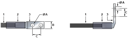
1 Insulated wire 3 Lug B 1/2” 2 Heat-shrink tubing A 1/4” C 5/8” Note: Dimension B is the width of the lug (not visible on the right angle lug).
Connecting a DC Power Supply to Power Source
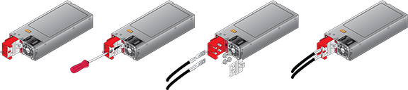
Figure 7 displays an example of connecting a PSU. To connect a DC power supply to a power source, perform the following:
- Replace the terminal covers as required.
Figure 7. DC PSU Connection Example
Connecting Serial and Management Cables
The accessory kit includes the following cables:
- RJ-45 to DB-9 serial adapter cable.
- RJ-45 Ethernet cable.
Table 2 lists the pin connections of the RJ-45 to DB-9 adapter cable.
| RJ-45 | DB-9 | RJ-45 | DB-9 | |||||
|---|---|---|---|---|---|---|---|---|
| RTS | 1 | 8 | CTS | GND | 5 | 5 | GND | |
| DTR | 2 | 6 | DSR | RXD | 6 | 3 | TXD | |
| TXD | 3 | 2 | RXD | DSR | 7 | 4 | DTR | |
| GND | 4 | 5 | GND | CTS | 8 | 7 | RTS | |
The front panel contains the console, management, and USB ports. Figure 8 displays the ports on the DCS-7050SX-128 switch. Front Panel displays the front panel of all switches covered by this guide.
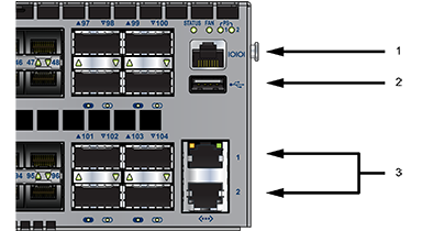
| 1 | Console serial port | 2 | USB port | 3 | Ethernet management ports |
Connect the front panel ports as follows:
-
Console (Serial) Port: Connect to a PC with the RJ-45 to DB-9 serial adapter cable. The switch uses the following default settings:
- 9600 baud
- No flow control
- 1 stop bit
- No parity bits
- 8 data bits
- Ethernet Management Port: Connect to 10/100/1000 management network with RJ-45 Ethernet cable.
-
USB Port: The USB port may be used for software or configuration updates.
CAUTION: Excessive bending can damage interface cables, especially optical cables.Flexion excessive peut endommager les câbles d'interface, notamment des câbles optiques.