Rack Mounting the Switch
The following topics are covered in this section:
Les procédure de montage du bâti est identique pour tous les commutateurs visés par ce guide. Illustrations dans ce chapitre montrent le montage d'un interrupteur de DCS-7050SX-128.
After completing the instructions for your rack type, proceed to Cabling the Switch.
Two-Post Rack Mount
To mount the switch onto a two-post rack, assemble the mounting brackets to the chassis, then attach the brackets to the rack posts. Two-post accessory kits includes 2 three-hole mounting brackets.
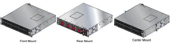
Each chassis side has attachment pins that align with bracket holes; the number of pins (six or seven) varies by switch model. Pin orientation is symmetric and equidistant, supporting bracket placement where the flange is either flush with the front and rear panels, or not flush with the panels. Each bracket hole includes a key-opening for placing the bracket flush with the chassis and then locking it into place.
Goupilles de fixation doivent s’engager tous les trois trous de la bride supérieure.
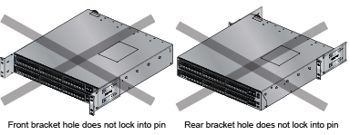
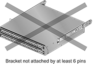
Bracket Mount Examples for Two-Post Rack Mount displays proper bracket mount configuration examples. Improper Bracket Mount Examples for Two-Post Rack Mount displays improper bracket mount configuration examples.
Attaching Mounting Brackets to the Chassis
This procedure attaches mounting brackets to the switch chassis
- Slide the bracket toward the front flange until the bracket clip locks with an audible click.
Figure 3. Attaching the Mounting Brackets to the Switch Chassis 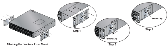
To remove the mounting bracket from the chassis, lift the front edge of the mounting bracket clip with a flathead screwdriver and slide the bracket away from the front flange (opposite from the installation direction).
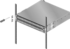
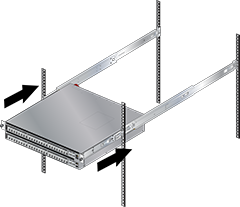
Inserting the Switch into the Rack
This procedure attaches the switch to the rack.
- Lift the chassis into the rack. Position the flanges against the rack posts.
Figure 4. Inserting the Switch into the Rack
Four-Post Rack Mount
The switch is mounted onto a four-post rack by assembling two rails onto the rear posts, sliding the switch onto the rails, then securing the switch to the front posts.
- Six-hole mounting bracket
- Rail
Each chassis side has attachment pins that align with bracket holes; the number of pins (six or seven) varies by switch model. Pin orientation is symmetric and equidistant, supporting bracket placement where the flange is either flush with the front and rear panels, or not flush with the panels. Each bracket hole includes a key-opening for placing the bracket flush with the chassis and then locking it into place.
Goupilles de fixation doivent s’engager tous les trous de support six.
Figure 5 displays proper bracket mount configuration examples. Figure 6 displays an improper bracket mount configuration examples.
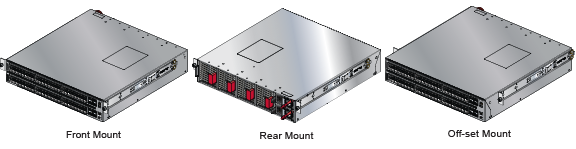
Off-set mount is always an improper bracket mount configuration on switches that have six attachment pins on each side.
Extracting the Brackets and the Rails
Figure 7 displays a bracket-rail assembly and the component pieces (bracket and rail) that are extracted from the assembly. Each assembly must be separated into its component pieces before mounting the switch into a four-post rack. The two assemblies supplied with the switch are identical.
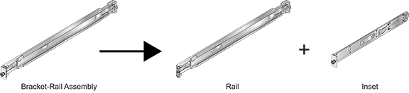
This procedure separates a bracket-rail assembly into its component pieces.
- Grip the rail with your right hand, as shown in Extracting the Bracket Rail Assembly-Left. Pull the bracket flange away from the rail flange with your left hand until the bracket clip catches on the rail (Extracting the Bracket Rail Assembly-Right).
If the bracket flange resists initially, verify the thumb screw on the bracket flange is not attached to the rail flange.
Figure 8. Extracting the Bracket-Rail Assembly
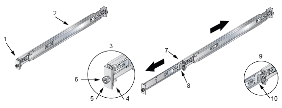
1 Inset A 5 Bracket flange 9 Inset B (detail) 2 Rail (Grip here) 6 Thumb screw 10 Locking clip 3 Inset A (detail) 7 Inset B 4 Rail flange 8 Locking clip
Attaching Mounting Brackets to the Chassis
The Figure 9 displays the front bracket alignment for mounting the switch into a four-post rack.
This procedure attaches mounting brackets to the switch chassis as depicted by Figure 10.
- Slide the bracket toward the front flange until the bracket clip locks with an audible click.
Figure 9. Front Bracket Alignment 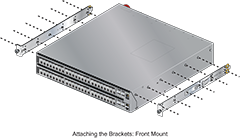
To remove the mounting bracket from the chassis, lift the front edge of the mounting bracket clip with a flathead screwdriver and slide the bracket away from the front flange (opposite from the installation direction).
Figure 10. Attaching the Mounting Brackets to the Switch Chassis
1 Bracket Clip 2 Bracket Clip
Expanding the Rails
The rail is initially contracted and must be expanded to attach onto the rack. This procedure expands the rails from their contracted state:
- Pull the ends apart until the rail-clip makes an audible click (Expanding the Rails-Right).
Figure 11. Expanding the Rails
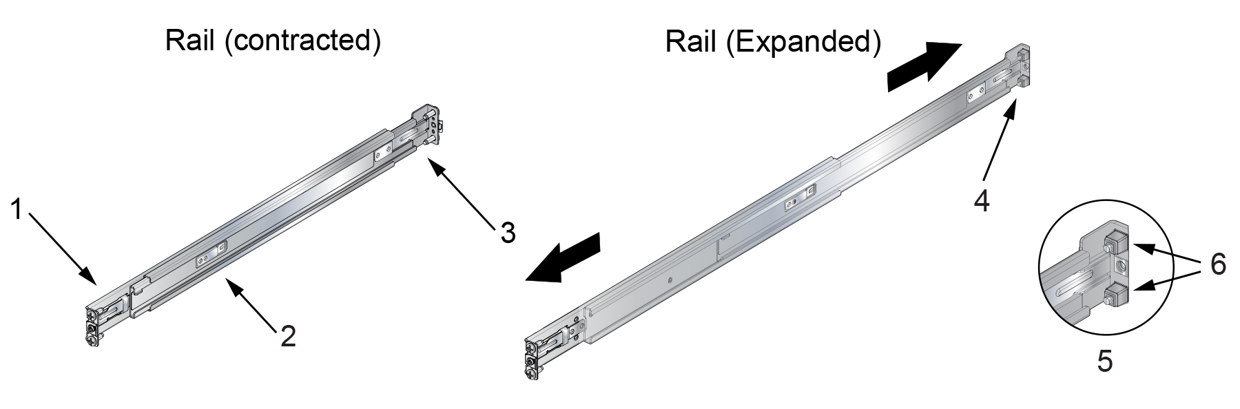
1
Rail-slide end (grip with left hand)
3
Rail-rod end (grip with right hand)
5
Inset A (detail)
2
Rail clip
4
Inset A
6
Rack plugs
Assembling the Rails onto the Equipment Rack
- Repeat Step 1 through Step 2 for the left posts. Ensure the rails are on the same horizontal level.
Figure 12. Attaching the Rails
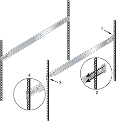
1 Inset A 3 Inset B 2 Inset A (detail) 4 Inset B (detail)
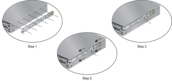
Attaching the Switch to the Rack
- Slide the switch on the rails, toward the rear posts, until the mounting bracket flanges are flush with the rail flanges attached to the rack posts.
Figure 13. Inserting the Switch onto the Rails
- Attach the bracket flanges to the rack post using the quick-release thumb screws supplied with the brackets.
Figure 14. Attaching the Switch to the Rack Posts
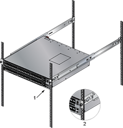
1 Inset A 2 Inset A (detail) After completing the four-post rack mount, proceed to Cabling the Switch.