Mounting the Switch
This section provides instructions on how to mount the switch in different ways.
The following topics are covered in this section:
Desktop Mount
This section provides instructions for mounting the switch on the desktop or any flat surface.
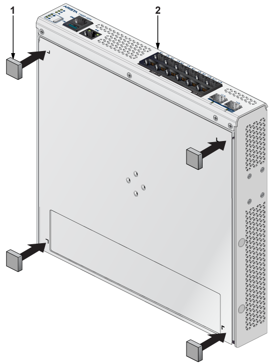
| 1 | Rubber feet | 2 | Front panel |
Note: Make sure that the device is not stacked and avoid placing anything on the top of the device.
Magnetic Mount (Optional)
This section provides instructions for mounting the switch using a arubber magnet.
Note:Magnetic mounting is applicable to mount only on the metal surfaces.
Note:
- Horizontal mount height is limited to 1.6m.
- Vertical mount height is limited to 1.6m.
- Ceiling mount is not supported.
- High vertical wall mount is not supported.
- Do not pull on the wires/cables connected to the product, as this may cause the product to fall and potentially result in injury.
| 1 | Rubber magnet | 3 | Rear panel |
| 2 | 3-in-1 bracket | 4 | Flat head screw M4x6mm |
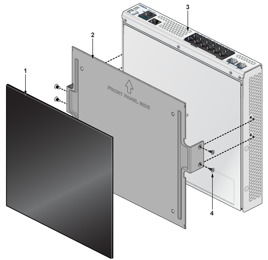
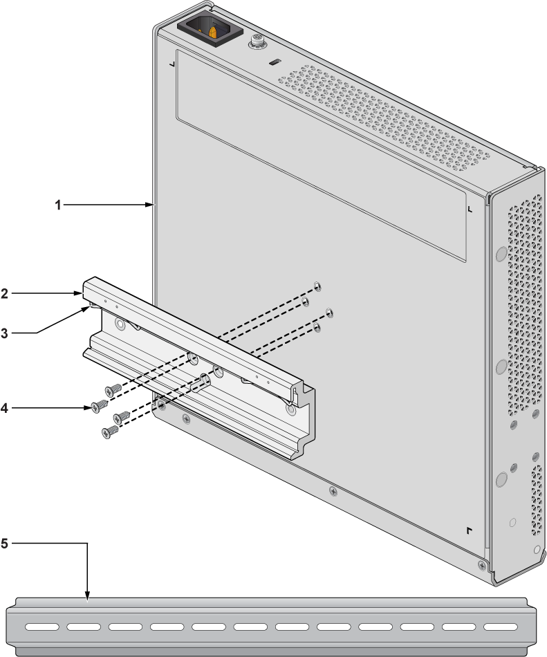
L-Bracket Wall Mount (Optional)
This section provides instructions for wall mounting the switch using an L-Bracket.
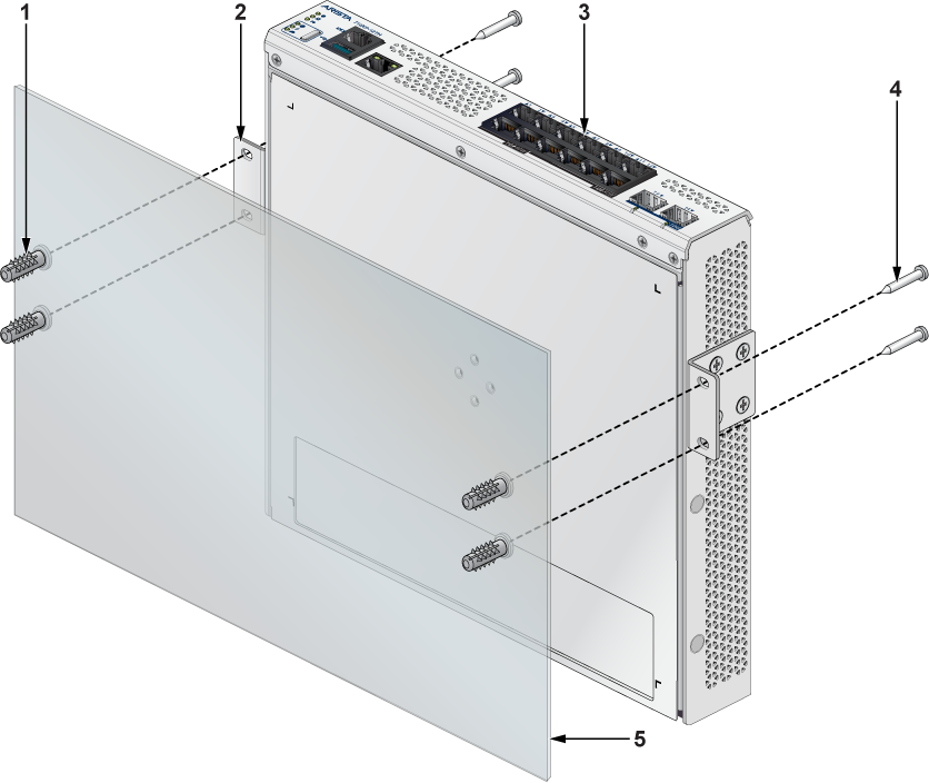
| 1 | Screw anchor M4 | 4 | Screw M4x25mm |
| 2 | L-Bracket | 5 | Flat surface |
| 3 | Front panel |
- Position the L-Bracket aligning with the chassis holes on each side of the switch and secure it with screws.
- Determine the mounting position to attach the switch to the wall.
- Drill four holes (two on each side) 7x25mm deep on the wall.
- Insert M4 screw anchor to the four holes drilled on the wall.
- Place the chassis, attached with L-Bracket, on the wall aligning with the mounting holes and secure the device with screws.
- Tighten the screws to secure the device firmly to the wall.
L-Bracket Under Table Mount (Optional)
This section provides instructions for mounting the switch under the table/desk using an L-Bracket.
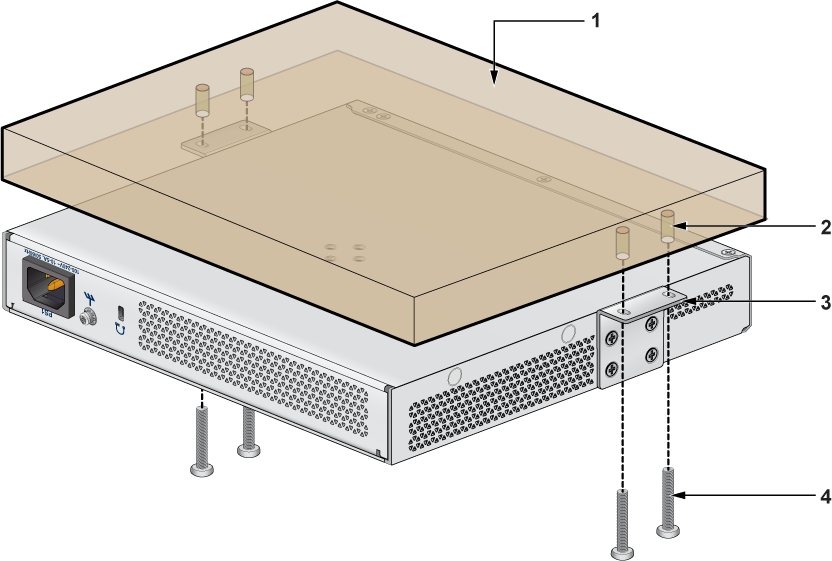
| 1 | Flat wooden table | 3 | L-Bracket |
| 2 | Screw anchor M4 | 4 | Screw M4x25mm |
Note: Ensure that the flat wooden surface has a minimum thickness of 25mm for under table mounting.
- Position the L-Bracket aligning with the chassis holes on each side of the switch and secure it with screws.
- Determine the mounting position to attach the switch under the table.
- Place the chassis, attached with L-Bracket, under the table and secure the device with screws.
- Tighten the screws to secure the device firmly under the table.
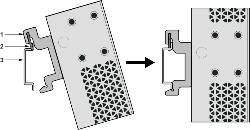
DIN Rail Mount (Optional)
This section provides instructions for mounting the switch usingaDIN rail.
| 1 | Chassis | 4 | Flat head screw M4x6mm |
| 2 | DIN mount bracket | 5 | DIN rail |
| 3 | DIN rail hook |
- Attach the DIN rail to the mounting bracket with the help of DIN rail hook as shown in the below image.
1 DIN mount bracket 3 DIN rail holder 2 DIN rail hook 4 DIN rail
Two-post Rack Mount (Optional)
This section provides instructions for rack mounting the switch.
Attaching Mounting Brackets to the Chassis
This section describes the steps to attach mounting brackets to the switch chassis.
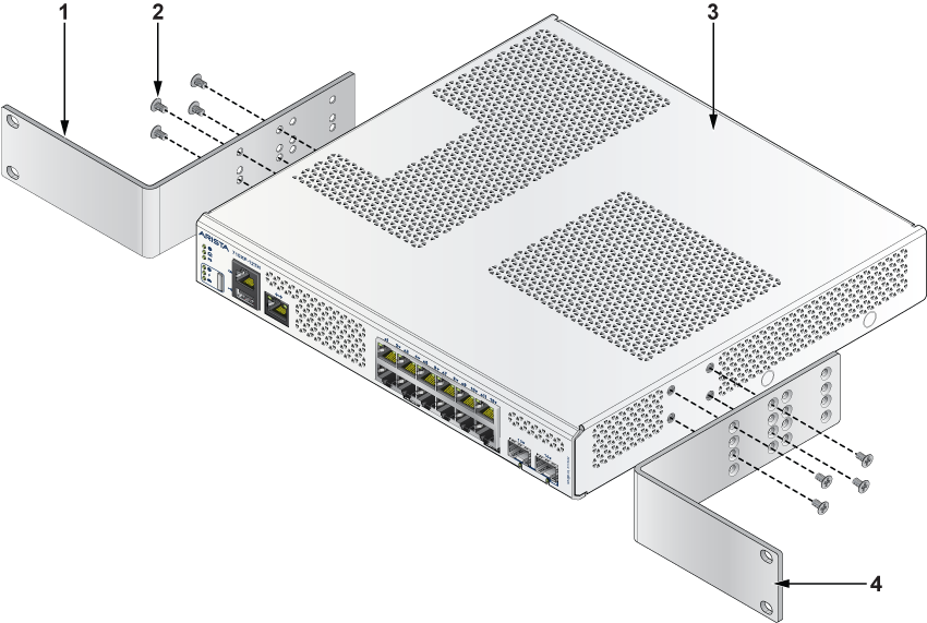
| 1 | L-bracket | 3 | Chassis |
| 2 | Flat head screw M4x6mm | 4 | L-bracket |
Note: Ensure that there is about 1U rack spacing between the two devices on the rack.
- Align the rack mounting brackets with the chassis of the switch.
- Secure the mounting brackets firmly using the screws provided in the rack mounting kit.
Inserting the Switch into the Rack
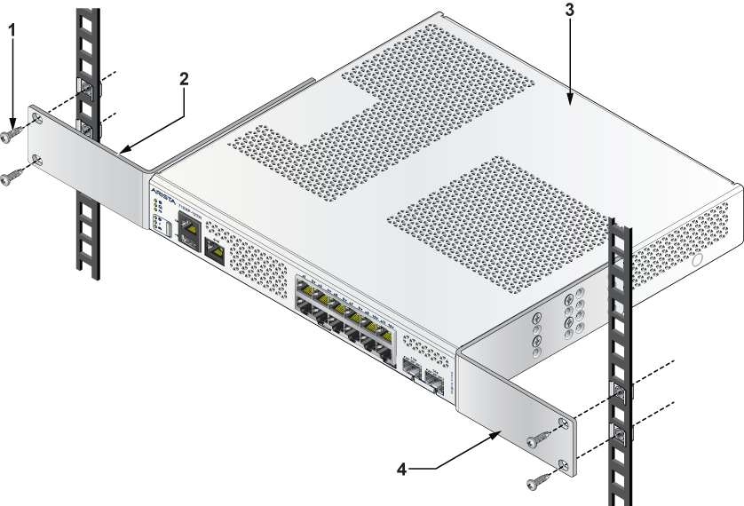
| 1 | Screw for cage nut | 3 | Chassis |
| 2 | L-bracket | 4 | L-bracket |
Note: Ensure that there is 1RU clearance above the rack mount bracket.
- Place the switch into the rack by aligning the mounting bracket with the chassis.
- Secure the switch into the rack using the thread screws provided in the rack mount kit.
- Position the rack against the rack posts and mount the rack to the equipment rack.
- Secure the equipment rack using the screws.