Mounting the Switch
The following topics are discussed in this section:
CCS-710XP-12TH-2S
This section provides instructions on how to mount the switch in different ways.
The following topics are discussed in this section:
Desktop Mount
This section provides instructions for mounting the switch on the desktop or any flat surface.
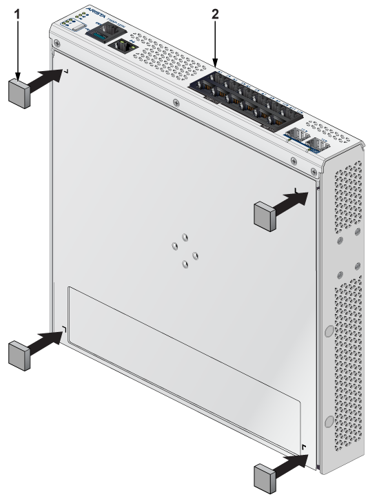
| 1 | Rubber feet | 2 | Front panel |
Magnetic Mount (Optional)
This section provides instructions for mounting the switch using a rubber magnet.
- Horizontal mount height is limited to 1.6m.
- Vertical mount height is limited to 1.6m.
- Ceiling mount is not supported.
- High vertical wall mount is not supported.
- Do not pull on the wires/cables connected to the product, as this may cause the product to fall and potentially result in injury.
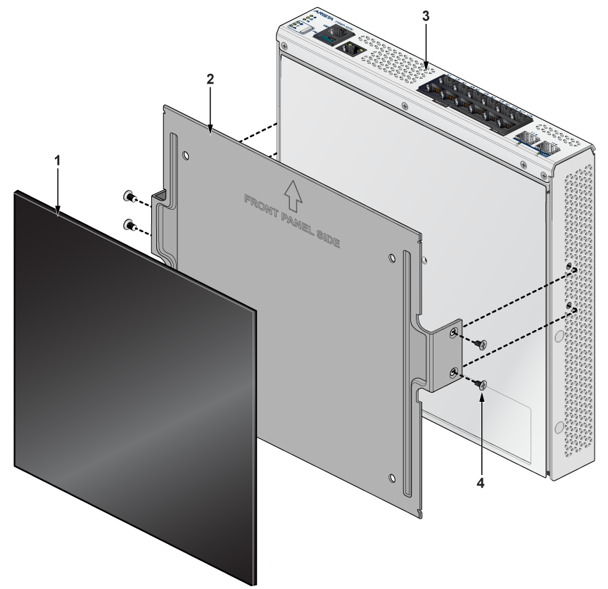
| 1 | Rubber magnet | 3 | Rear panel |
| 2 | 3-in-1 bracket | 4 | Flat head screw M4x6mm |
L-Bracket Wall Mount (Optional)
This section provides instructions for wall mounting the switch using an L-Bracket.
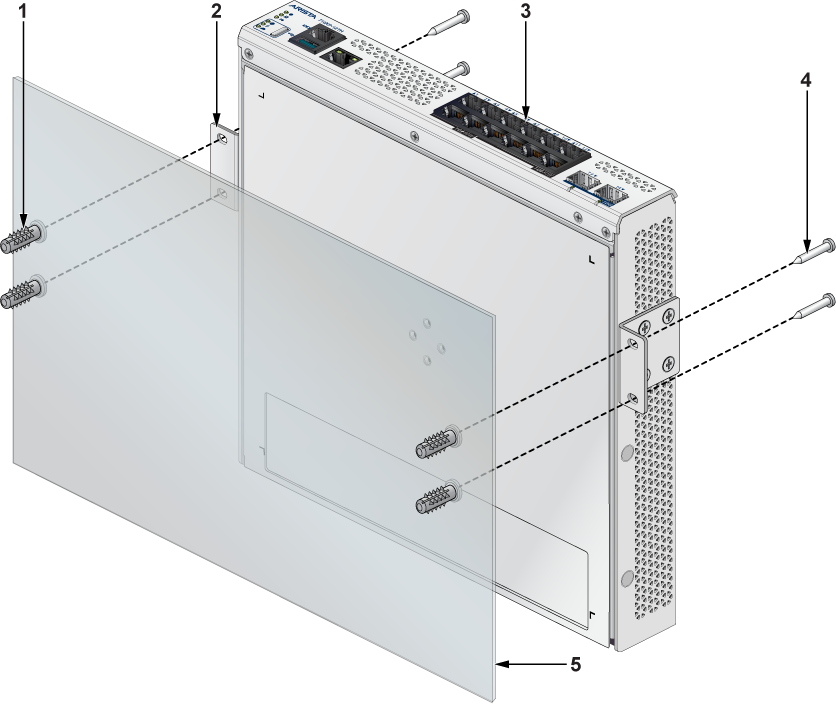
| 1 | Screw anchor M4 | 4 | Screw M4x25mm |
| 2 | L-Bracket | 5 | Flat surface |
| 3 | Front panel |
- Position the L-Bracket aligning with the chassis holes on each side of the switch and secure it with screws.
- Determine the mounting position to attach the switch to the wall.
- Drill four holes (two on each side) 7x25mm deep on the wall.
- Insert M4 screw anchor to the four holes drilled on the wall.
- Place the chassis, attached with L-Bracket, on the wall aligning with the mounting holes and secure the device with screws.
- Tighten the screws to secure the device firmly to the wall.
L-Bracket Under Table Mount (Optional)
This section provides instructions for mounting the switch under the table/desk using an L-Bracket.
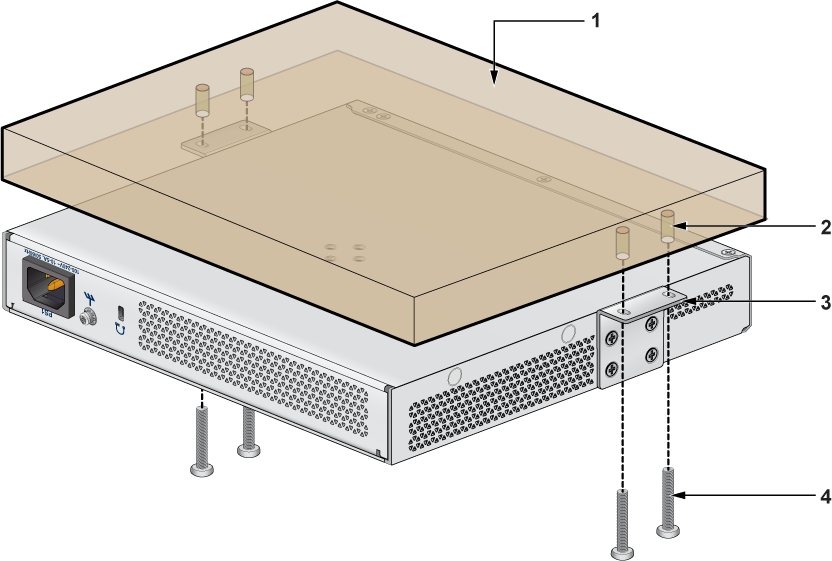
| 1 | Flat wooden table | 3 | L-Bracket |
| 2 | Screw anchor M4 | 4 | Screw M4x25mm |
- Position the L-Bracket aligning with the chassis holes on each side of the switch and secure it with screws.
- Determine the mounting position to attach the switch under the table.
- Place the chassis, attached with L-Bracket, under the table and secure the device with screws.
- Tighten the screws to secure the device firmly under the table.
DIN Rail Mount (Optional)
This section provides instructions for mounting the switch usinga DIN rail.
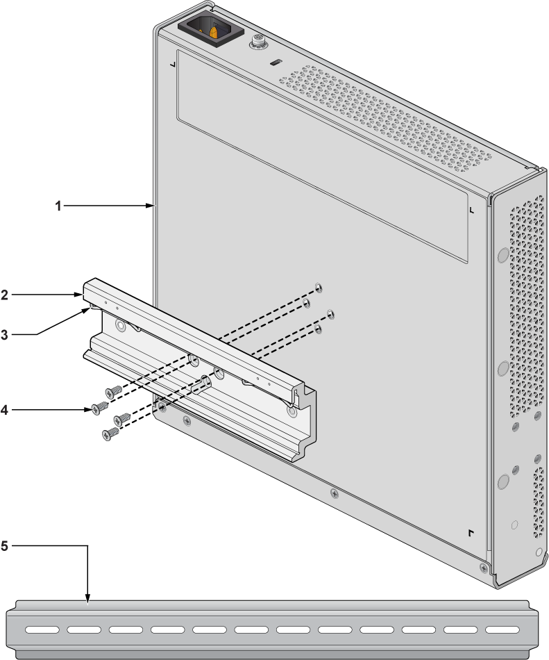
| 1 | Chassis | 4 | Flat head screw M4x6mm |
| 2 | DIN mount bracket | 5 | DIN rail |
| 3 | DIN rail hook |
- Attach the DIN rail to the mounting bracket with the help of DIN rail hook as shown in the below image.
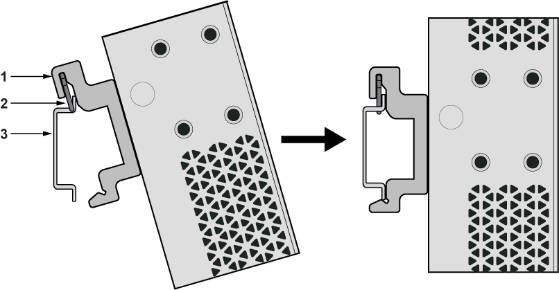
1 DIN mount bracket 3 DIN rail holder 2 DIN rail hook 4 DIN rail
Two-post Rack Mount (Optional)
This section provides instructions for rack mounting the switch.
Attaching Mounting Brackets to the Chassis
This section describes the steps to attach mounting brackets to the switch chassis.
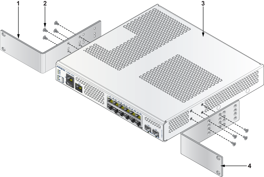
| 1 | L-bracket | 3 | Chassis |
| 2 | Flat head screw M4x6mm | 4 | L-bracket |
- Align the rack mounting brackets with the chassis of the switch.
- Secure the mounting brackets firmly using the screws provided in the rack mounting kit.
Inserting the Switch into the Rack
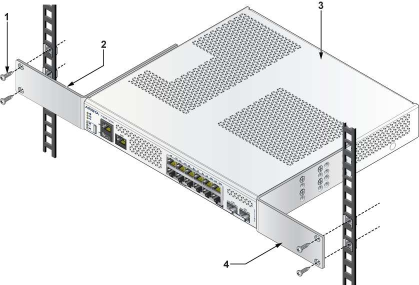
| 1 | Screw for cage nut | 3 | Chassis |
| 2 | L-bracket | 4 | L-bracket |
- Place the switch into the rack by aligning the mounting bracket with the chassis.
- Secure the switch into the rack using the thread screws provided in the rack mount kit.
- Position the rack against the rack posts and mount the rack to the equipment rack.
- Secure the equipment rack using the screws.
CCS-710XP-28TNH-2S
This section provides instructions on how to mount the switch in different ways.
The following topics are discussed in this section:
Two-post Rack Mount
This section provides instructions for rack mounting the switch.
Attaching Mounting Brackets to the Chassis
This section describes the steps to attach mounting brackets to the switch chassis.
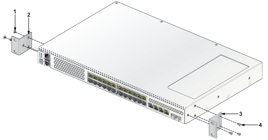
| 1 | Flat head screw M4x6mm | 3 | L-bracket |
| 2 | L-bracket | 4 | Flat head screw M4x6mm |
- Align the rack mounting brackets with the chassis of the switch.
- Secure the mounting brackets firmly using the screws provided in the rack mounting kit.
Inserting the Switch into the Rack
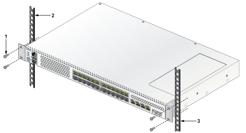
| 1 | Screw for cage nut | 3 | Two-post rail |
| 2 | Two-post rail |
- Place the switch into the rack by aligning the mounting bracket with the chassis.
- Secure the switch into the rack using the thread screws provided in the rack mount kit.
- Position the rack against the rack posts and mount the rack to the equipment rack.
- Secure the equipment rack using the screws.
Four-post Rack Mount
This section provides instructions for mounting the switch in a four-post rack.
The switch is mounted onto a four-post rack by assembling two rails onto the rear posts, sliding the switch onto the rails, and then securing the switch to the front posts.
- Two six-hole mounting brackets
- Two rail rods
- Two rail slides
The rail rods and rail slides assemble into two identical slide rails.
Each chassis side has attachment pins that align with bracket holes. Pin orientation is symmetric and equidistant, supporting bracket placements where the flange is flush with the front panel, flush with the rear panel, or not flush with either panel. Each bracket hole includes a key-opening for placing the bracket flush with the chassis and then locking it into place.
Attachment pins must engage at least five of the six bracket holes.
Goupilles de fixation doivent être lock au moins cinq des trous du six support.
Attaching Mounting Brackets to the Chassis
This section describes the steps to attach mounting brackets to the chassis.
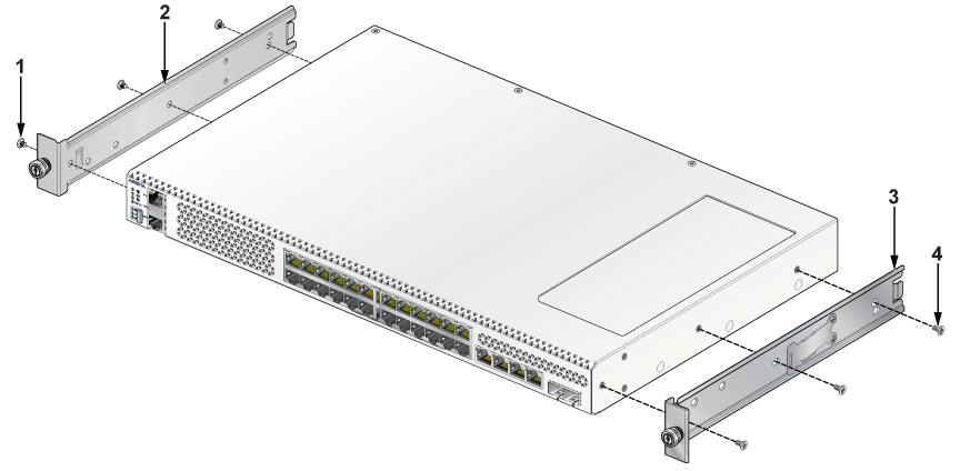
| 1 | Flat head screw M4x6mm | 3 | Mounting bracket (right) |
| 2 | Mounting bracket (left) | 4 | Flat head screw M4x6mm |
Assembling the Rails onto the Equipment Rack
Rail rods and rail slides assemble into two identical rails. Each rail connects a front post to a rear post. When the rails are installed, the switch slides on the rails into the rack. Each bracket includes a screw that attaches the switch to the rail.
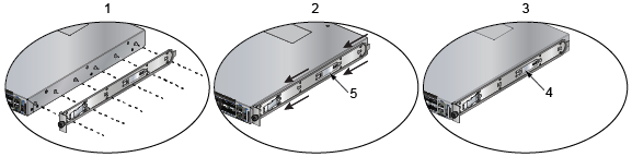
| 1 | Attach rail slide to the switch | 4 | Bracket clip (attached) |
| 2 | Slide rail rod onto rail slide | 5 | Bracket clip (aligned) |
| 3 | Attach bracket clip |
- Slide a rail rod into a rail slide until the rail clip makes an audible click.
The rail clip prevents the rail from extending beyond the maximum supported distance between the front and rear rack posts.
Figure 12. Assembling the Rails 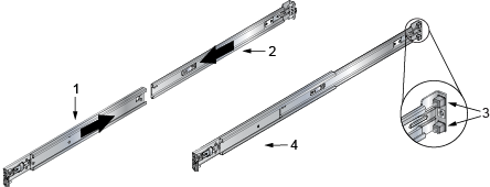
1 Rail slide 3 Rack plugs 2 Rail rod 4 Rail (assembled) - Repeat Step 1 through Step 3 for the left posts. Ensure the rails are on the same horizontal level.
Figure 13. Attaching the Rails 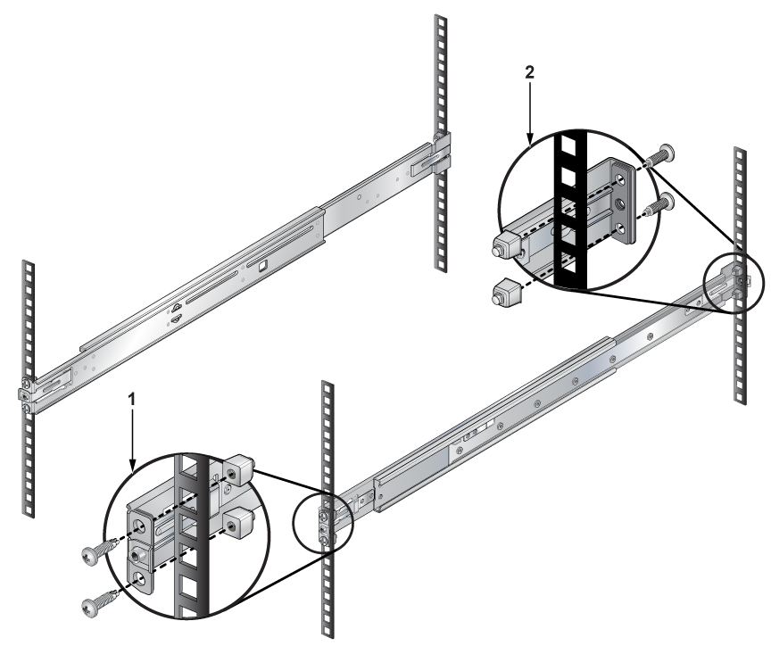
1 Inset A 2 Inset B
Attaching the Switch into the Rack
Once the rails are installed, the switch slides into the rack. Each bracket includes a thumb screw that attaches the switch to the rail.
- Lift the switch into the rack and insert the mounting brackets into the slide rails.
Figure 14. Inserting the Switch onto the Rails 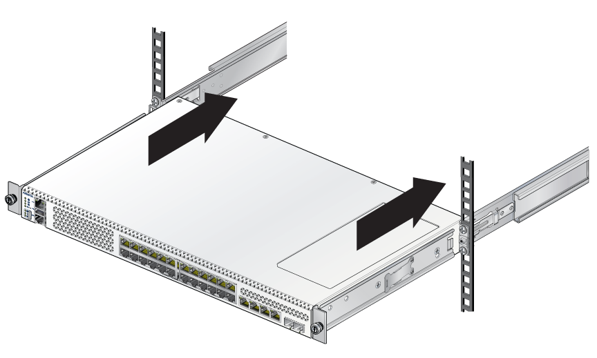
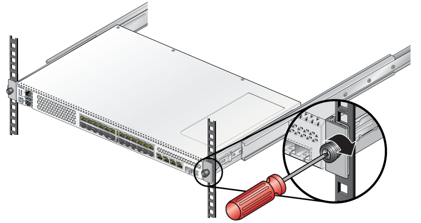
- Attach the bracket flanges to the rack post using the quick-release thumb screws supplied with the brackets.
Figure 15. Attaching the Switch to the Rack Posts