Status Indicators
Supervisor Module
- one serial console port.
- two Ethernet management ports (one RJ-45, one optical).
- one USB port.
- two QSFP100 (CCS-750-SUP100) or four SFP25 (CCS-750-SUP25) supervisor/uplink ports.
- several system level status indicator LEDs Status Indicators.
System Level Status Indicator LEDs: CCS-750-SUP100
The system status indicator LEDs are shown in Figure 1 - Supervisor CCS-750-SUP100 and Figure 2 - Supervisor CCS-750-SUP25 .
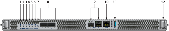
| 1 | Supervisor status LED | 5 | Switch card status LED | 9 | Ethernet management ports |
| 2 | Supervisor active status LED | 6 | Fan status LED | 10 | RJ-45 Serial console port |
| 3 | PSU status LED | 7 | Uplink status LED | 11 | USB Port |
| 4 | Linecard status LED | 8 | QSFP100 uplink ports | 12 | Release/locking mechanism (Right)1 |
1 There is a similar mechanism on the left.
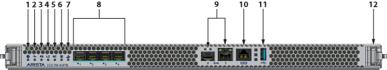
| 1 | Supervisor status LED | 5 | Switch card status LED | 9 | Ethernet management ports |
| 2 | Supervisor active status LED | 6 | Fan status LED | 10 | RJ-45 Serial console port |
| 3 | PSU status LED | 7 | Uplink status LED | 11 | USB Port |
| 4 | Linecard status LED | 8 | SFP25 uplink ports | 12 | Release/locking mechanism1 |
1 There is a similar mechanism on the left.
Supervisor Status LEDs Behavior
Supervisor Status LED
Table 1 - Supervisor Status LED States interprets the states of the supervisor status LED. s for both the active and the redundant supervisor module.
| State | Status |
|---|---|
| Off | Supervisor has no power or is powering up. |
| Blinking Green | Supervisor is booting. System can take up to 30 minutes to come up. All other LEDs will also be off. |
| Green | Supervisor is operating normally (master supervisor). System is good. |
| Yellow/Amber/Orange | System is overheating or has been disabled by software. |
| Blinking Blue | Locater function enabled by CLI (Beacon). |
Supervisor Active Status LED
Table 2 - Supervisor Active Status LED States interprets the states of the supervisor active status LED.
| State | Status |
|---|---|
| Off | Supervisor is the standby supervisor. All other LEDs except Supervisor Status remain off. |
| Green | Supervisor is the Active supervisor. |
PSU Status LED
Table 3 - PSU Status LED States interprets the states of the PSU status LED.
| State | Status |
|---|---|
| Off | PSU not detected, installed or powered. |
| Green | All installed PSUs are operating normally. |
| Red | One or more PSU has a fault. |
Linecard Status LED
Table 4 - Linecard Status LED States interprets the states of the Linecard status LED.
| State | Status |
|---|---|
| Off | Linecard not detected, installed or powered. |
| Green | All installed linecards are operating normally. |
| Yellow/Amber/Orange | One or more linecard is booting up or being updated. |
| Red | One or more linecards have failed. |
Switchcard Status LED
Table 5 - Switchcard Status LED States interprets the states of the switchcard status LED.
| State | Status |
|---|---|
| Off | Switchcard not detected, installed or powered. |
| Green | All installed switchcards are operating normally. |
| Yellow/Amber/Orange | One or more switchcard is booting up or being updated. |
| Red | One or more switchcards have failed. |
Fan Status LED
Table 6 - Fan Status LED States interprets the states of the Fan status LED.
| State | Status |
|---|---|
| Off | No fan detected. |
| Green | All installed fans are operating normally. |
| Yellow/Amber/Orange | One or more fans has failed or is missing. |
| Red | Fans are insufficient or incompatible. |
Management Ethernet Port Status LED
Table 7 - Management Ethernet Port Status LED States interprets the states of the management Ethernet port status LED.
| LED | State | Status |
|---|---|---|
| Left | Off | Port is not linked up. |
| Left | Green | Port is linked up. |
| Right | Off | Port has no activity. |
| Right | Green | Port has activity. |
Uplink Status LED
Table 8 - Uplink Status LED States interprets the states of the uplink status LED.
| State | Status |
|---|---|
| Off | Supervisor is not powered up or inserted. |
| Green | Uplink card is operating normally. |
| Yellow/Amber/Orange | Uplink card is booting up or being updated. |
| Red | Uplink card power has failed. |
Linecard Module Indicators
Each linecard module provides one status LED plus LEDs for each port on the card.Figure 3 - Linecard Module Status LEDs shows a representative line card. The figures in Linecards indicate the location of the LEDs on each linecard.
.png)
| 1 | Linecard module status LED | 2 | Port status LED |
Linecard Module Status LEDs Behavior
Table 9 - Linecard Module Status LED States interprets the states of the linecard module status LED located on the individual linecard.
Linecard Module Status LED
| State | Status |
|---|---|
| Off | Linecard not inserted or powered. |
| Green | Linecard operating normally. |
| Yellow/Amber/Orange | Linecard is booting up or being updated. |
| Blinking Red | Locater function is enabled (Beacon). |
| Red | Linecard has failed. |
Table 10 - Port Status LED States interprets the states of the port status LED located by each port on the linecard.
| State | Status |
|---|---|
| Off | Port link is down. |
| Green | Port link is up. |
| Yellow/Amber/Orange | Port is being administered by software. |
| Blinking Yellow/Amber/Orange | Locater function is enabled (Beacon). |
Switchcard Module Status Indicators
Rear Panel displays the position of the Switchcard Module Status LEDs on the rear of each switch. Figure 4 - 755 Switchcard Module and Fan Module Status LEDs displays fan module status and switch card module status LEDs on the 755 switch.
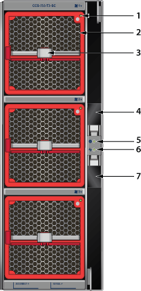
| 1 | Fan module 1 status LED | 4 | Switchcard release | 7 | Switchcard release |
| 2 | Fan module 1 | 5 | Switchcard module status LED | ||
| 3 | Fan module 1 release | 6 | Switchcard module active status LED |
758 Switchcard Module and Fan Module Status LEDs displays fan module status and switchcard module status LEDs on the 758 switch.
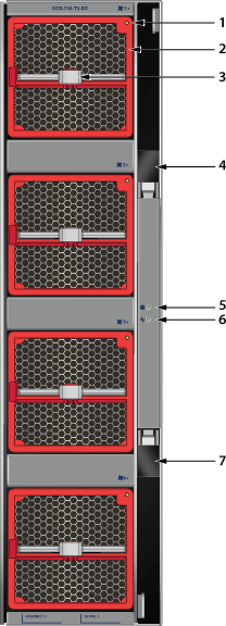
| 1 | Fan module 1 status LED | 4 | Switchcard release | 7 | Switchcard release |
| 2 | Fan module 1 | 5 | Switchcard module status LED | ||
| 3 | Fan module 1 release | 6 | Switchcard module active status LED |
Switchcard Module Status LEDs Behavior
There are two LEDs for the Switchcard status. Only one of the switch cards is active. The second provides redundancy. The switchcard module LEDs are on the rear panel of the switches.
Switchcard Module Status LED
Switchcard Module Status LED States interprets the states of the switchcard module status LED.
| State | Status |
|---|---|
| Off | Switchcard does not have power. |
| Green | All installed switchcards are working normally. |
| Yellow/Amber/Orange | Switchcard is booting up or being updated. |
| Red | One or more switchcards have failed. |
Switchcard Module Active Status LED
Switchcard Module Active Status LED States interprets the states of the switchcard module active status LED.
| State | Status |
|---|---|
| Off | Switchcard is in standby mode. |
| Green | Switchcard is in active mode. |
Fan Module Status Indicators
The fan module status LED are on the fan modules.Figure 6 - Fan Module Status LED displays the LED on the fan module.
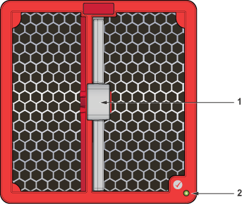
| 1 | Release | 2 | Fan module status LED |
Table 13 - Fan Module Status LED States interprets the states of the switch card module active status LED.
| State | Status |
|---|---|
| Off | Fan does not have power. |
| Green | Fan module is working normally. |
| Flashing red | Locater function is enabled (Beacon). |
| Red | Fan module has failed. |
Power Supply Status Indicators
The power supply status LED ison the power supply modules.Figure 7 - AC Power Supply (PWR-3351-AC-RED) displays the LED on the PWR-3351-AC-RED AC power supply.
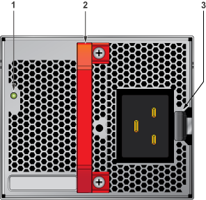
| 1 | Status LED | Handle | 3 | Release |
Table 14 - AC Power Supply Status LED States interprets the AC power supply module LED status indicators with multiple PSU present in the system.
| State | Status |
|---|---|
| Off | No AC Input or 140V < AC < 175V - single PSU. |
| Blinking Amber1 | No AC Input or 140V < AC < 175V – multiple PSUs. |
| Blinking Green1 | Standby Mode. |
| Green | Normal Operation. |
| Amber | PSU module has failed. |
| Blinking Amber and Green2 | Boot Loader. |
1 1 second ON, 1 second OFF.
2 1 second ON, alternating.