Preparation
Site Selection
The following criteria should be considered when selecting a site to install the switch.
- Floor Space: Install the switch in an area that provides adequate clearance for removing front and rear components.
- Figure 1 - Clearance Requirements and Footprint for Switches displays the dimensions and footprint of the switch clearance requirements for the switches.
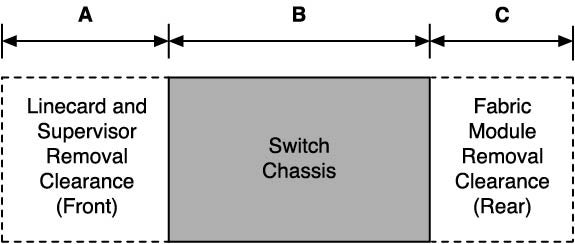
Table 1 - Clearance Requirements and Footprint Dimensions shows the dimensions for each of the modular switches.
| Switch | Clearance Requirements Dimensions | ||
|---|---|---|---|
| A | B | C | |
| CCS-755 | 24.2 cm
(9.5 in.) |
94.0 cm
(16.5 in.) |
35.1 cm
(13.8 in.) |
| CCS-758 | 24.2 cm
(9.5 in.) |
94.0 cm
(16.5 in.) |
35.1 cm
(13.8 in.) |
- Temperature and Ventilation: For proper ventilation, install the switch where there is ample airflow to the front and back of the switch. The temperature should not go below 0° or exceed 40°C.
Important:
To prevent the switch from overheating, do not operate it in an area where the ambient temperature exceeds 40°C (104°F).
Pour empêcher l'interrupteur de surchauffe, ne pas utiliser il dans une zone où la température ambiante est supérieure à 40°C (104°F).
- Airflow Orientation: The fans direct air from the front panel to the rear panel. Orient the front panel toward the cool aisle.
- Rack Space Requirements: Table 2 -Rack Space Requirements shows the rack space requirements for each of the modular switches.
Table 2. Rack Space Requirements Switch Rack or Cabinet (standard 19" EIA) Mount Kit 2-post 4-post Switch Height (RU) CCS-755 KIT-CCS-750-2P KIT-CCS-750-4P 7 CCS-758 KIT-CCS-750-2P KIT-CCS-750-4P 10 Note: The accessory kit provides the required mounting hardware for each switch. - Power Requirements: Arista switches require a minimum number of operating power supplies in all chassis, and for each power domain of switches with multiple power domains. Refer to Cabling the Modular Switch for more details regarding your switch.
- Other Requirements: Select a site where liquids or objects cannot fall onto the equipment and foreign objects are not drawn into the ventilation holes. Verify these guidelines are met:
- Clearance areas to the front and rear panels allow for unrestricted cabling.
- All front and rear panel indicators can be easily read.
- AC power cords can reach from the AC power outlet to the input connectors.
Tools and Parts Required for Installation
The following tools are required to install a modular switch.
- Mechanical device capable of lifting chassis being installed. (Table 3 - Rack Component Requirements.)
- Torque reading nut driver (for DC power supplies).
- #2 Phillips head screwdriver.
Rack Mount: Shows the Rack Components Required for each of the Modular Switches.
The following table shows the rack components required for each of the modular switches.| Switch | Rack or Cabinet (standard 19" EIA) | ||
|---|---|---|---|
| Rack screws(1) | Rack Nuts(2) | Notes | |
| CCS-755 | 14 | 14 | 2-post installation, 4-post installation |
| CCS-758 | 18 | 18 | 2-post installation, 4-post installation |
The accessory kit includes screws that fit many common equipment racks.
Rack nuts are only for racks with unthreaded, rack-post holes.
Electrostatic Discharge (ESD) Precautions
Observe these guidelines to avoid ESD damage when installing or servicing the switch.
- Assemble or disassemble equipment only in a static-free work area.
- Use a conductive work surfaces (such as an anti-static mat) to dissipate static charge.
- Wear an ESD wrist strap to dissipate static charge accumulation.
- Minimize handling of assemblies and components.
- Keep replacement parts in their original static-free packaging.
- Remove all plastic, foam, vinyl, paper, and other static-generating materials from the work area.
- Use tools that do not create ESD.