Rack Mounting the Switch
- Front
- Center
- Back (rear)
Attaching Mounting Brackets to the CCS-755 Two-post and Attaching Mounting Brackets to the CCS-758 for Two-post show examples for attaching mounting ears to the CCS-755 and CCS-758 chassis to support each of the three mounting locations.
Illustrations in this chapter depict the mounting of a chassis in a single orientation. After completing the instructions for your rack type, proceed to Cabling the Modular Switch.
Two-post Rack Mount
The switch can be mounted in either forward orientation (line cards and supervisors facing forward) or backward orientation (fans and PSUs facing forward). For each of these orientations, the switch supports a front, center or rear mount into a two-post rack.
- Two-post rack cradle
- mounting brackets
- 18 screws
Note: The following illustrations highlight a front-mount.
Rack Mounting the CCS-755 for Two-post
To mount the switch to the rack, perform the following tasks.
- Attach the mounting brackets to the switch for the desired orientation and position supported. (Attaching Mounting Brackets to the CCS-755 Two-post.)
- Insert and secure the two-post cradle to the rack. (Attaching Cradle to the Racks for 755 Two-post.)
- Insert and secure the switch into the rack. (Inserting and Securing CCS-755 Chassis into Two-post Rack.)
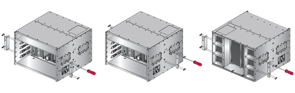
Attaching Mounting Brackets to the CCS-755 Two-post
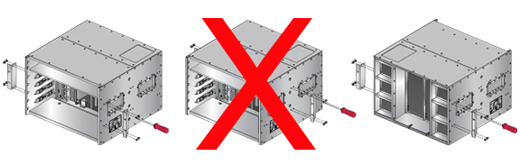
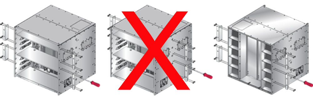
Attach the mounting brackets to both sides of the chassis using the screws provided in the kit for the desired orientation and position. The following figure shows the CCS-755 chassis with the mounting brackets for Forward-Front, Forward-Center, and Backward-Front mounting.
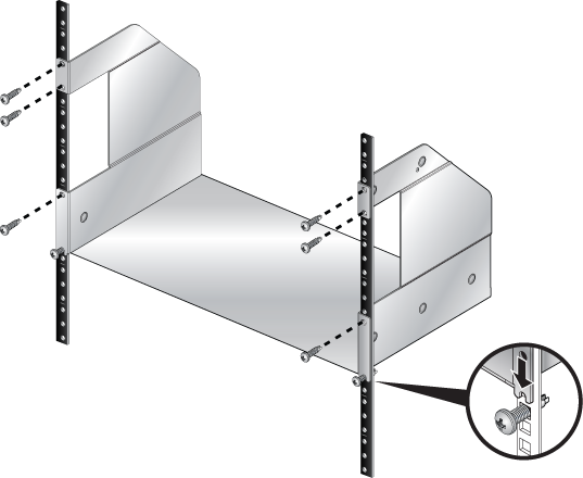
Attaching Cradle to the Racks for 755 Two-post
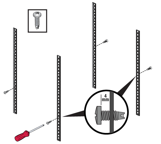
Attach the two-post cradle to the rack using the screws provided as shown in the following figure. Use rack nuts if needed.
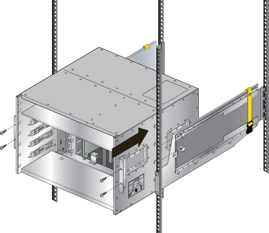
Inserting and Securing CCS-755 Chassis into Two-post Rack
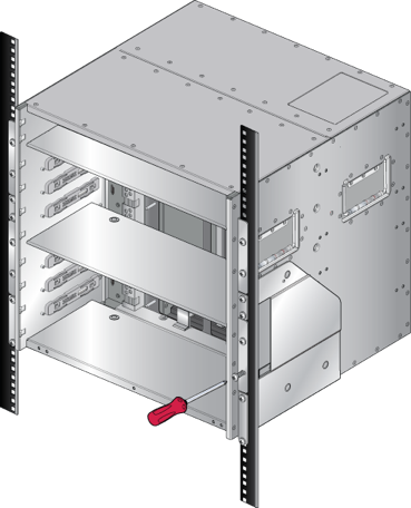
- Lift and slide the chassis into the rack cradle in the desired orientation.
Note:The following figure shows an unthreaded rack example with rack nuts.
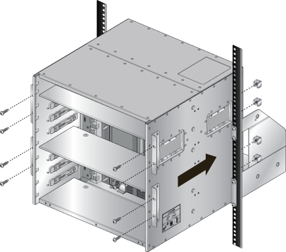
Figure 3. Inserting the Switch into the Two-post Rack (CCS-755 Forward-Front)
.png)
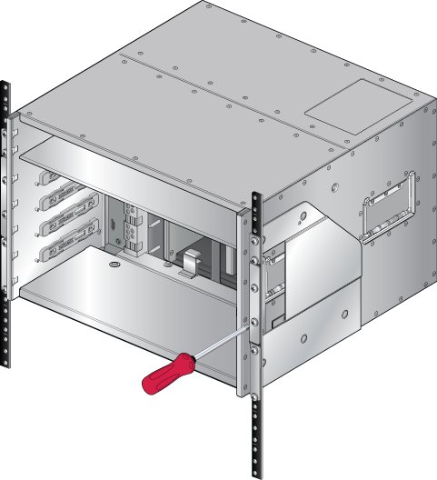
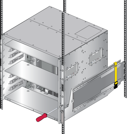
- Secure the chassis to the rack as shown in the following figure.
Figure 4. Securing the Chassis (CCS-755 Forward-Front)
After completing the two-post Installation, proceed to Cabling the Modular Switch.
Rack Mounting the CCS-758 for Two-post
To mount the switch to the rack, perform the following tasks:
- Attach the mounting bracket(s) to the switch for the desired orientation and position supported Attaching Mounting Brackets to the CCS-758 for Two-post.
- Insert and secure the two-post cradle to the rack Attaching Cradle to the Racks for 758 for Two-post.
- Insert and secure the switch into the rack Inserting and Securing CCS-758 Chassis into Rack for Two-post.
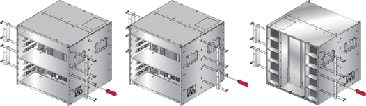
Attaching Mounting Brackets to the CCS-758 for Two-post
Attach the mounting brackets to both sides of the chassis using the screws provided in the kit for the desired orientation and position. The following figure shows the CCS-758 chassis with the mounting brackets for Forward-Front, Forward-Center, and Backward-Front mounting.
Attaching Cradle to the Racks for 758 for Two-post
Attach the two-post cradle to the rack using the screws provided. Use rack nuts if needed.
Inserting and Securing CCS-758 Chassis into Rack for Two-post
- Lift and slide the chassis into the rack cradle in the desired orientation.
Note: The following figure shows an unthreaded rack example with rack nuts.
Figure 7. Inserting the Switch into the Two-post Rack (758 Forward-Front)
- Secure the chassis to the rack as shown in the following figure.
Figure 8. Securing the Chassis (758 Forward-Front)
After completing the two-post Installation, proceed to Cabling the Modular Switch.
Four-post Rack Mount (Optional)
The switch can be mounted in either forward orientation (line cards and supervisors facing forward) or backward orientation (fans and PSUs facing forward) in a four-post rack.
- 4-post rack cradle
- mounting brackets
- 18 screws
Rack Mounting the CCS-755 for Four-post
To mount the switch to the rack, perform the following tasks.
- Attach the mounting brackets to the switch for the desired orientation and position supported Attaching Mounting Brackets to the CCS-755 for Four-post.
- Insert and secure the two-post cradle to the rack Attaching Cradle to the Racks for 755 Two-post .
- Insert and secure the switch into the rack Inserting and Securing the Switch into the Rack for Four-post 755.
Attaching Mounting Brackets to the CCS-755 for Four-post
Attach the mounting brackets to both sides of the chassis using the screws provided in the kit for the desired orientation and position. The following figure shows the CCS-755 chassis with the mounting brackets for Forward-Front, Forward-Center, and Backward-Front mounting.
Inserting and Securing the Cradle to the Racks for Four Post 755
- Insert two screws loosely in the two front rack posts and two in the back two rack posts at the same level for the figure below.
Figure 10. Attaching Mounting Screws to the Rack Posts for 755
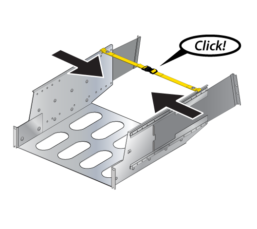
- Buckle the straps on the cradle together, prior to installation, so the left and right sides are angled slightly inwards for the figure below.
Figure 11. Buckling the Straps
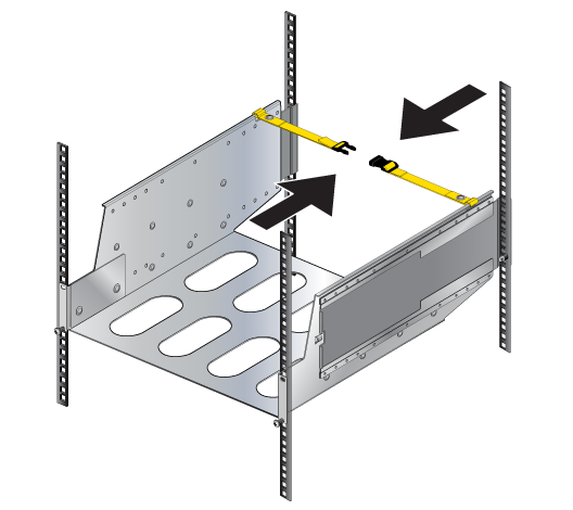
- Pull out the rear sliding rails slightly beyond the back rack posts.
- Insert the cradle so that the notches in the cradle engage behind the loosely mounted front screws for the figure below.
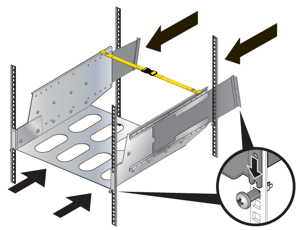
- Slide the rear sliding rails back in so that they are flush with the back rack posts, the notches in the cradle engage behind the loosely mounted screws, and the bottom of the cradle is horizontal and level for the figure below.
Figure 12. Inserting the Cradle
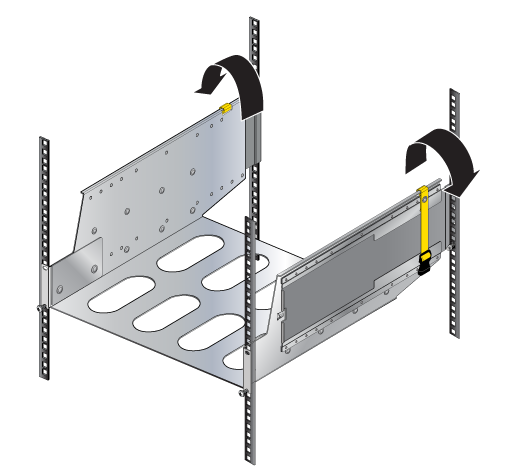
- Release the clasp on the connector to rotate the left and right sides so they are vertical for the figure below.
Figure 13. Aligning the Cradle in the Rack
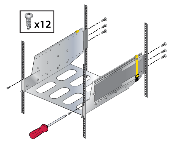
- Secure the cradle to the rack posts using the remaining screws, and tighten the loosely mounted screws for the figure below.
Figure 14. Securing the Cradle in the Rack
Inserting and Securing the Switch into the Rack for Four-post 755
- Move the chassis to the rack using a mechanical lift.
Note: If modules are inserted in the chassis, use the lift carefully to avoid damaging any components.
- Lift the chassis into the rack and slide it into the cradle for the figure below.
Figure 15. Inserting the Chassis (755 Forward-Front)
- Secure the chassis by tightening additional screws on the front flanges into the rack posts for the figure below.
Figure 16. Securing the Chassis (755 Forward-Front)
After completing the Four-Post Installation, proceed to Cabling the Modular Switch.
Rack Mounting the CCS-758 for Four-post
To mount the switch to the rack, perform the following tasks:
- Attach the mounting bracket(s) to the switch for the desired orientation and position supported Attaching Mounting Brackets to the Four Post CCS-758.
- Insert and secure the two-post cradle to the rack Attaching Cradle to the Racks for 758 for Two-post.
- Insert and secure the switch into the rack Inserting and Securing the Switch into the Four-post Rack 758.
Attaching Mounting Brackets to the Four Post CCS-758
Inserting and Securing the Cradle to the Racks for Four Post CCS-758
To insert and secure the cradle assembly to the rack use the following steps.
- Insert two screws loosely in the two front rack posts and two in the back two rack posts at the same level for the figure below.
Figure 18. Figure 3-18: Attaching Mounting Screws to the Rack Posts for 758
- Buckle the straps on the cradle together, prior to installation, so the left and right sides are angled slightly inwards for the figure below.
Figure 19. Figure 3-19: Buckling the straps
- Pull out the rear sliding rails slightly beyond the back rack posts.
- Insert the cradle so that the notches in the cradle engage behind the loosely mounted front screws for the figure below.
- Slide the rear sliding rails back in so that they are flush with the back rack posts, the notches in the cradle engage behind the loosely mounted screws, and the bottom of the cradle is horizontal and level for the figure below.
Figure 20. Figure 3-20: Inserting the cradle
- Release the clasp on the connector to rotate the left and right sides so they are vertical for the figure below.
Figure 21. Figure 3-21: Aligning the cradle in the rack
- Secure the cradle to the rack posts using the remaining screws, and tighten the loosely mounted screws for the figuer below.
Figure 22. Figure 3-22: Securing the cradle in the rack
Inserting and Securing the Switch into the Four-post Rack 758
- Lift the chassis into the rack and slide it into the cradle.
Figure 23. Inserting the Chassis (758 Forward-Front)
- Secure the chassis by tightening additional screws on the front flanges into the rack posts (Figure 24 - Securing the Chassis (758 Forward-Front)).
Figure 24. Securing the Chassis (758 Forward-Front)
After completing the Four-Post Installation, proceed to Cabling the Modular Switch.