Maintenance and Field Replacement
This section discusses the following topics:
Considerations
- All fans and power supplies are hot swappable.
- The switch can be running while a power supply is being installed or removed, but the power supply being replaced must not be connected to a power source.
- All slots must be filled or covered with a blank for operation (even though power supply or fans may not be functional).
- Before you begin, refer to the Arista Networks document Safety Information and Translated Safety Warnings available at: https://www.arista.com/en/support/product-documentation.
Note: Descriptions for the removal and replacement of power supplies and fans are only for a representative power supply or fan. Locations of status indicator LEDs may differ. Refer to the front (Front Panel) and rear (Rear Panel) panel illustrations of your device to locate the appropriate LED, the release lever or handle, and the handle for the module.
Power Supplies
The following steps are required when removing power supplies from a switch.
Removing a Power Supply
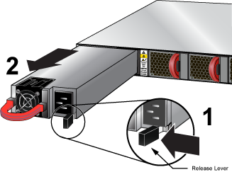
- Push the power supply release lever and remove the power supply (Figure 1).
Figure 1. Remove Power Supply
Installing a Power Supply
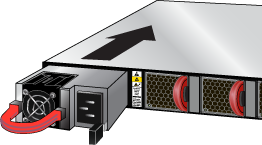
- Slide the new power supply into the switch until the power supply is fully seated and the release lever snaps into place (Figure 2).
Figure 2. Install Power Supply
Fan Modules
Note: Hot swap fans within 30 seconds to prevent the switch from overheating. Ensure that the module you are replacing matches those already installed in the switch.
Removing a Fan Module
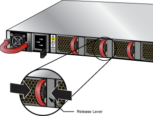
- Push the fan module release lever and slide the fan module out of the switch (Figure 3).
Figure 3. Removing Fan Module
Installing a Fan Module
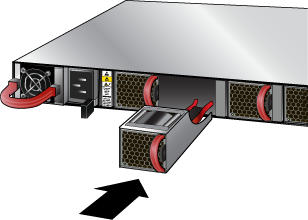
- Slide the new fan module into the switch until the module is fully seated and the release lever snaps into place (Figure 4).
Figure 4. Inserting the Fan Module
 Note: The fan module status LED should be a steady green for normal operation.