Status Indicators
Front Indicators
Switch Indicators
The front panel LEDs, fan, and power supply status are on the chassis display system.
The front panel LEDs are labeled, as shown in the following figure.
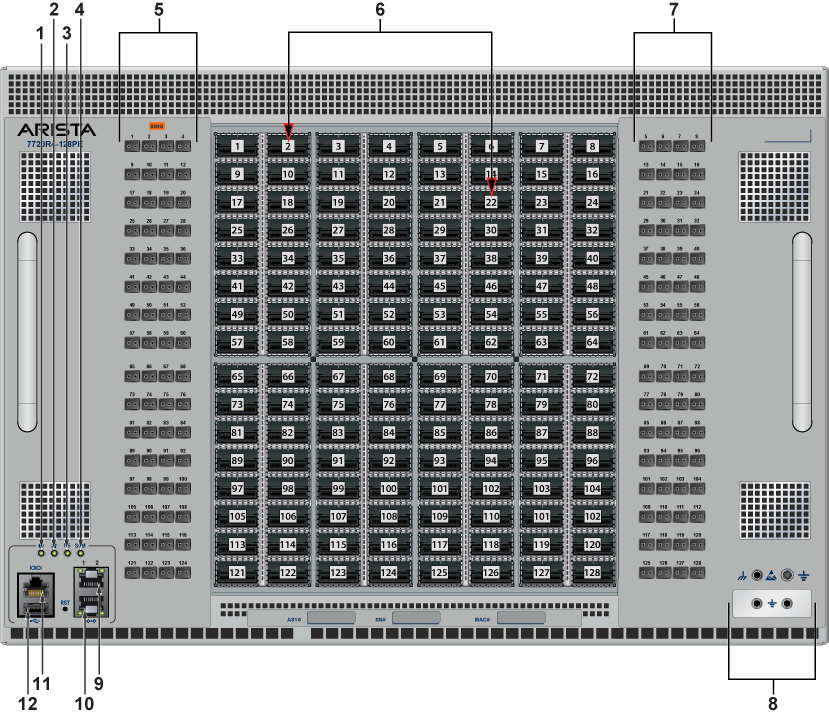
| 1 | System status LED | 5 | Port status LED | 9 | Ethernet management port (RJ45) |
| 2 | Fan status LED | 6 | Port numbers | 10 | Ethernet management port (RJ45) |
| 3 | Power supply status LED | 7 | Port status LED | 11 | Console (serial) port |
| 4 | Supervisor card module status LED | 8 | Grounding | 12 | USB port |
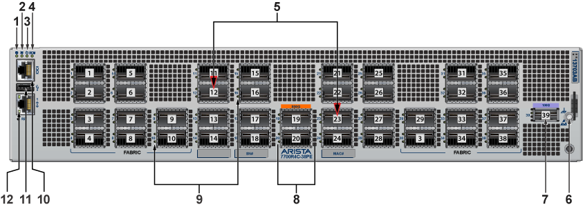
| 1 | System status LED | 5 | Port numbers | 9 | Port status LEDs |
| 2 | Fan status LED | 6 | Port numbers | 10 | Ethernet management port (RJ45) |
| 3 | Power supply status LED | 7 | 100G Port number | 11 | USB port |
| 4 | Supervisor card module status LED | 8 | Port status LEDs | 12 | Ethernet management port (RJ45) |
| LED Name | LED State | Device Status |
|---|---|---|
| System Status LED | Blinking Green | System is powering up. |
| Green | Normal operations. Due to power supply and fan redundancy, this LED will remain green if a single fan or power supply is missing or in a failed state. | |
| Blue | The beacon (locator) function is active. | |
| Amber | Two or more fans (any combination of fan modules or PSU fans) are disconnected or malfunctioning. The switch will automatically execute a “graceful shutdown” shortly. | |
| Fan Status LED | Green | All fan and power modules are operating normally. |
| Amber | Single fan module is removed or malfunctioning. It is also amber when a PSU is completely removed or has a stuck fan rotor. | |
| Red | Two or more fans (any combination of fan modules or PSU fans) are disconnected or malfunctioning. The switch will automatically execute a “graceful shutdown” shortly. | |
| Supervisor Active LED | Green | PSU is functioning and fully operational. AC is present, Aux output is ON, and Main output is ON. |
| Off | PSU has been removed or is not operating properly due to the AC cord being unplugged, its fan rotor being stuck, or an internal fault. | |
| Port Status LED | Flashing dim purple | System booting. |
| Off | Default/System not powered up. |
Port Indicators
Port LEDs near their corresponding ports provide a link and operational status.
The following figure displays the Port LED location on the switch.
Table 2 - Port LED States (Front) provides status conditions that correspond to port LED states.
| LED State | Status |
|---|---|
| Off | No signal for enabled interfaces. |
| Green | Any enabled interface is connected, AND no link is bad. |
| Yellow (amber/orange) | All interfaces are software disabled, or a link is bad. |
| Flashing Yellow (amber/orange) | Port failed diagnostics. |
Rear Status Indicators
You can access the fan and power supply modules are accessed from the rear panel.
Each fan and power supply module contains an LED that reports the module status. The illustrations are for a typical fan module and PSU.
Fan Status LEDs are on the fan modules, as displayed in Figure 3 - Fan Status LED.
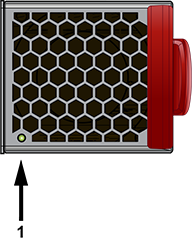
| 1 | Fan module status LED |
Table 3 - Fan Status LED States (Rear) provide conditions corresponding to fan status LED states.
| LED State | Status |
|---|---|
| Off | The fan module is not detected. If it is inserted, it may not be seated properly. |
| Green | The fan is operating normally. This LED state is exclusive to its fan module and independent of the states of its neighboring fans and power supplies. |
| Red | The fan has failed. |
The AC Power Supply Status LEDs are on the power supply modules, as displayed in Figure 4 - AC Power Supply Status LED.
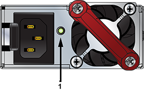
| 1 | Power supply status LED |
Table 4 - AC Power Supply Status LED States (Rear) provides conditions corresponding to the AC power supply status LED states.
| Power Supply State | PWR-2421 HV |
|---|---|
| Input power present Normal operation | Green |
| Input power present Power Supply fault | Yellow |
| No Input power Supply installed in chassis | Off |
| Input power present Supply not installed in chassis | Green |
The DC Power Supply Status LEDs are on the power supply modules, as displayed in Figure 5 - DC Power Supply Status LED. Depending on the power supply, the LED could be in a different location on the PSU.
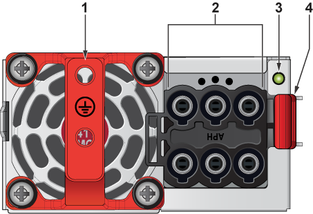
| 1 | Handle | 3 | Power supply status LED |
| 2 | Connector | 4 | Release |
Table 5 - DC Power Supply Status LED States (Rear) provides conditions corresponding to the DC power supply status LED states.
| Power Supply State | PWR-2411-MC |
|---|---|
| Input power present Normal operation | Green |
| Input power present Power Supply fault | Blinking Amber/Yellow |
| No Input power Supply installed in chassis | Off |
| Input power present Supply not installed in chassis | Blinking Amber/Yellow |