Rear Panel
All switches covered by this guide use the rear panel shown below.
Note: Depending on the installed power supply and fan modules, the appearance could be different from those shown.
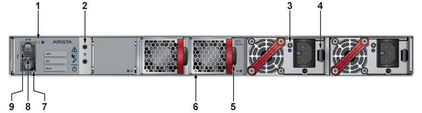
| 1 | System Status LED | 4 | Power supply 1 latch | 7 | Console serial port |
| 2 | Ground | 5 | Fan module 2 handle | 8 | USB port |
| 3 | Power supply 1 status LED | 6 | Fan module 2 status LED | 9 | Ethernet management port |
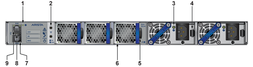
| 1 | System Status LED | 4 | Power supply 1 latch | 7 | Console serial port |
| 2 | Ground | 5 | Fan module 3 handle | 8 | USB port |
| 3 | Power supply 1 status LED | 6 | Fan module 3 status LED | 9 | Ethernet management port |