Rack Mounting the Switch
This section provides instructions on how to mount the switch in different ways.
The following topics are discussed in this section:
CCS-710HXP-28TXH-4S
This section discusses the following topics:
L-bracket Wall Mount (KIT-CCS-710HXP-WALL)
This section provides instructions for wall mounting the switch using an L-bracket.
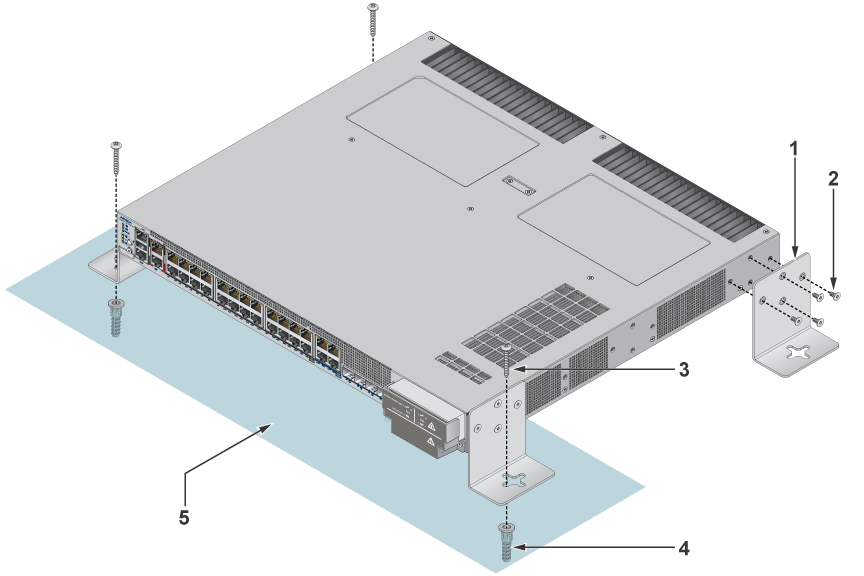
| 1 | L-bracket | 2 | Flat head screw M4x6mm | 3 | Screw M4x25mm |
| 4 | M4 screw anchor | 5 | Wall |
- Determine the mounting position to attach the switch to the wall.
- Position the L-bracket aligning with the chassis on each side of the switch.
- Drill four holes 7x25mm deepon the wall aligning with the L-brackets.
- Insert M4 screw anchor to the four holes drilled on the wall.
- Place the chassis along with the L-bracket on the wall aligning with the mounting holes.
- Tighten the screws to secure the device firmly to the wall.
- The L bracket wall mount is designed for a single, fixed mounting orientation as shown in the figure above. No alternative mounting directions or orientations are supported.
Two-post Rack Mount (KIT-CCS-710HXP)
This section provides instructions for two-post rack mounting the switch. These are the default mounting brackets, and they support different mounting locations: front, middle, and rear.
Attaching Mounting Brackets to the Chassis (Two-post)
This section describes the steps to attach mounting brackets to the switch chassis.
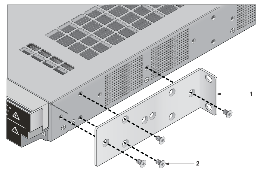
| 1 | L-bracket | 2 | Flat head screw M4x6mm |
- Align the rack mounting brackets with the chassis of the switch.
- Secure the mounting brackets firmly using the screws provided in the rack mounting kit.
Inserting the Switch into the Rack
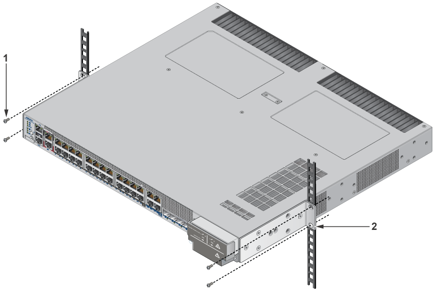
| 1 | Screw for cage nut | 2 | L-bracket |
- Place the switch into the rack by aligning the mounting bracket with the chassis.
- Secure the switch into the rack using the thread screws provided in the rack mount kit.
- Position the rack against the rack posts and mount the rack to the equipment rack.
- Tighten the screws to fix the device firmly.
Four-post Rack Mount (KIT-CCS-7010-4POST)
This section provides instructions for four-post rack mounting the switch.
Attaching Mounting Brackets to the Chassis (Four-post)
This section describes the steps to attach mounting brackets to the switch chassis.
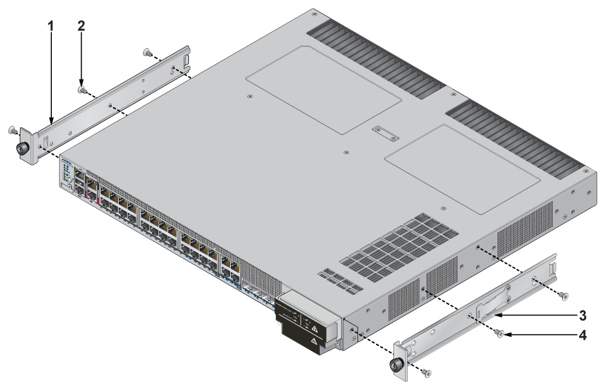
| 1 | Mounting bracket | 2 | Mounting screw | 3 | Bracket clip |
| 4 | Mounting screw |
- Align the mounting brackets with the attachment pins to obtain the desired mounting position.
- Place the bracket flush on the chassis with attachment pins protruding through key openings.
- Slide the bracket toward the front flange until the bracket clip locks with an audible click.
- Attach the deep chassis adapters as needed.
Assembling the Rails onto the Equipment Rack
This section describes the steps to attach the rails to a four-post rack.
Each end of an assembled rail contains two rack plugs. The rails are installed into a rack by inserting the plugs into rack slots. When installing rails into posts with threaded or rounded holes, remove all plugs on both sides of the assembled rails, then install the rails with bolts that fit the rack.
- Slide a rail rod into a rail slide until the rail clip makes an audible click.
The rail clip prevents the rail extension beyond the maximum supported distance between the front and rear rack posts.
Figure 5. Assembling the Rails
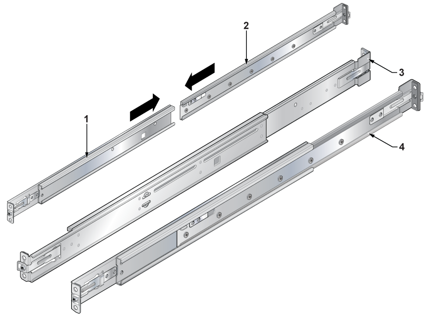
1 Rail slide 2 Rail slide 3 Rack plug 4 Rail slide - Attach the slide end of the rail to the front post by extending the rail end past the post, then contracting the rail while guiding the rack plugs into the post.
Figure 6. Attaching the Rails
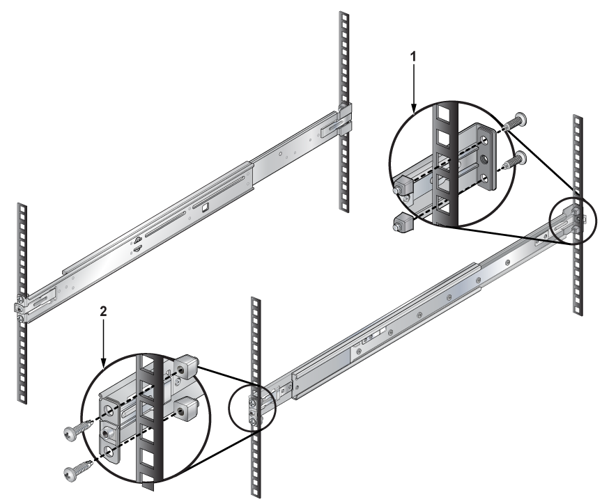
1 Inset A(Front) 2 Inset B(Rear)
Attaching the Switch to the Rack
This section describes the steps to attach the switch into a four-post rack.
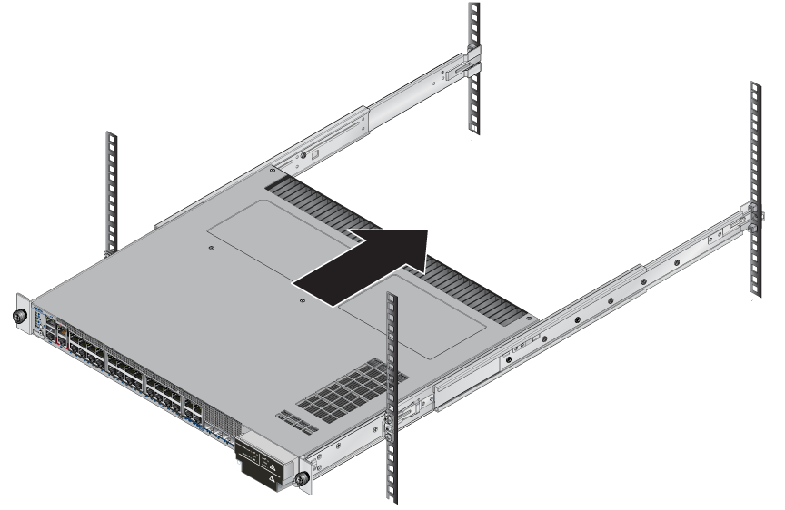
- Lift the switch into the rack and insert the mounting brackets into the slide rails.
Figure 7. Inserting the Switch onto the Rails
- Attach the bracket flanges to the rack post using the quick-release thumb screws supplied with the brackets. Hand-tighten the thumb screws or select a Phillips #2 screwdriver.
Note: Do not exceed a maximum torque of 20in-lb or use powered impact drivers to secure the thumb screws.
Figure 8. Attaching the Switch to the Rack Posts
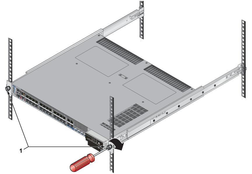
1 Rack plugs
CCS-710HXP-20TNH-4S
This section discusses the following topics:
DIN Rail Wall Mount (KIT-CCS-710HXP-DIN)
This section provides instructions for wall mounting the switch using a DIN Rail.
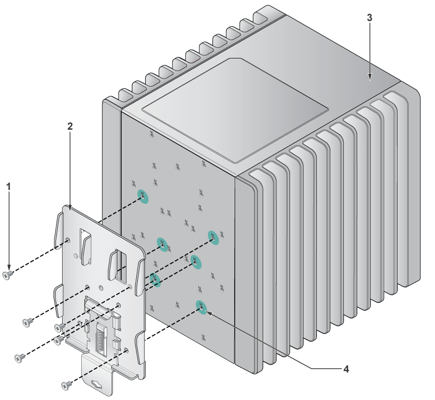
| 1 | Mounting screw M3*0.5*5 | 2 | DIN bracket | 3 | Switch |
| 4 | Mounting hole |
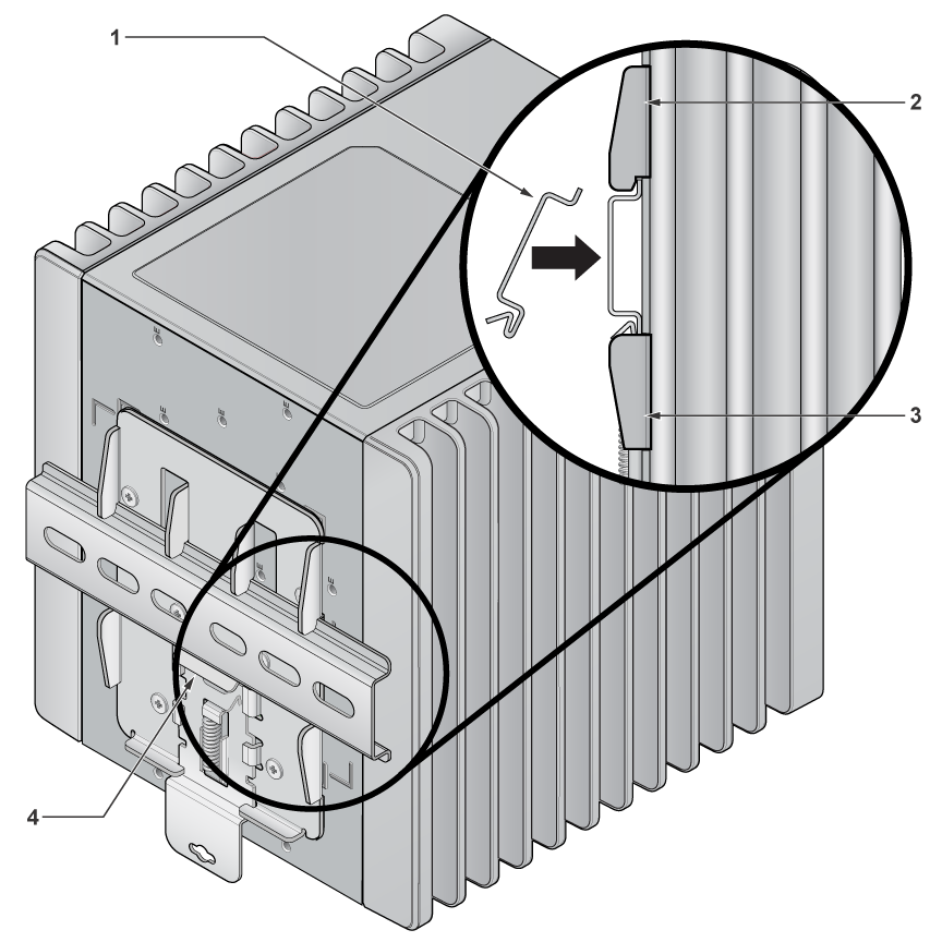
| 1 | DIN latch | 2 | DIN bracket | 3 | DIN bracket |
| 4 | DIN rail |
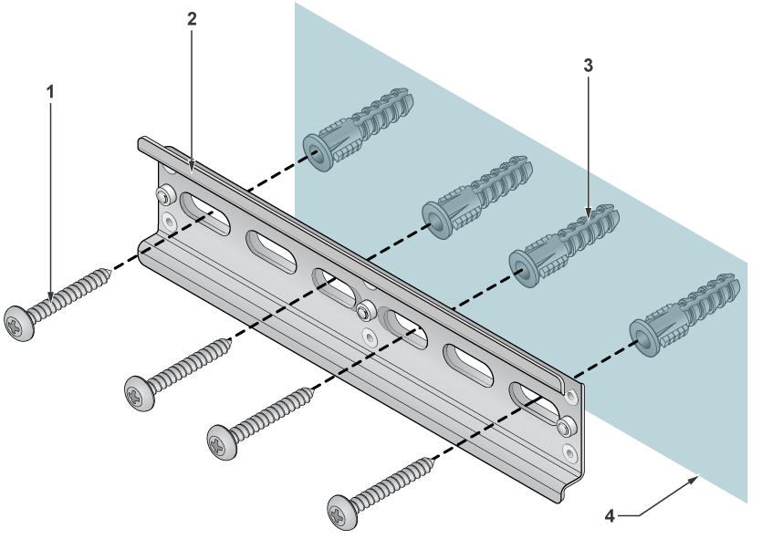
| 1 | Mounting screw M5*2*32 | 2 | Screw anchor | 3 | DIN rail |
| 4 | Wall surface |
- Position the DIN mount bracket aligning it with the mouting screws on the chassis.
- Place the DIN rail on the wall surface by aligning it with the DIN rail holder and mouting screws.
- Attach the DIN rail to the mounting bracket with the help of DIN latch and mouting screws. Tighten the screws to fix the device firmly.
DIN Rail Rack Mount (KIT-CCS-710HXP-DIN-RM)
This section provides instructions for rack mounting the switch using a DIN Rail.
| 1 | Mounting screw M3*0.5*5 | 2 | DIN bracket | 3 | Switch |
| 4 | Mounting hole | 4 |
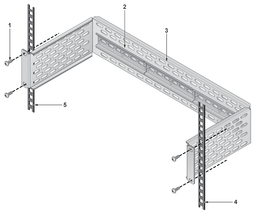
| 1 | Mounting screw | 2 | Rail | 3 | Two-post rack |
| 4 | Rack posts | 5 | Rack posts |
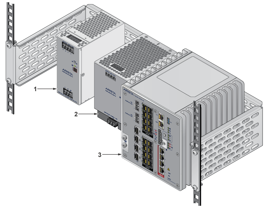
| 1 | PSU 1 | 2 | PSU 2 | 3 | Switch |