Cabling the Switch
Grounding the Switch
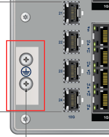
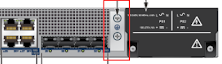
This section describes the importance of grounding the device to the data center ground.
Normally, the functional grounding of the switch is achieved through the input connection. If you would like to do additional grounding, proceed to the following instructions:
- Ensure the rack is properly grounded and complies with ETSI ETS 300 253.
- Verify a good electrical connection to the grounding point on the rack (no paint or isolating surface treatment).
- Attach the solder terminal lug to an 18 AWG minimum grounding wire and connect it to the grounding point on the rear panel of the switch.
- Tighten the M4 screw to secure the lug to the grounding point.
- Connect the other end of the wire to the nearby grounded surface.
Connecting Power Cables
This section describes the installation requirements for connecting the power cables to the device.
- Installation of this equipment must comply with local and national electrical codes. Consult with the appropriate regulatory agencies and inspection authorities to assure compliance if necessary.
Installation de cet équipement doit être conformes aux codes électriques locaux et nationaux. Si nécessaire, consulter les organismes de réglementation appropriés et des autorités de contrôle pour assurer la conformité.
- Read all installation instructions before connecting the system to the power source.
Lire toutes les instructions d'installation avant de brancher le système à la source d'alimentation.
- This equipment must be grounded. Never defeat the ground conductor.
Cet équipement doit être mis à la terre. Ne jamais modifier le conducteur de terre.
- This unit requires overcurrent protection.
Cet appareil requiert une protection contre les surintensités.
Connecting AC/HVDC Power on CCS-710HXP-28TXH-4S
This section describes how to connect the AC power supply to the device. The power inlet connector is a terminal block located on the front panel. PS1 and PS2 have its own terminal block connector.
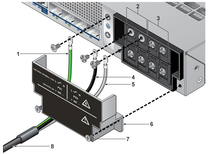
| 1 | Earth Ground Cable | 5 | Neutral/Negative Cable |
| 2 | PS1 Input Power Terminal Block | 6 | Protective Cover |
| 3 | PS2 Input Power Terminal Block | 7 | Securing Screw |
| 4 | Line/Positive Cable | 8 | Power Cable |
The same power supply, PWR-461-AC-H, supports AC and HVDC. The power ratings for each power inlet:
- AC input: 100–240 Vac, 50/60 Hz, 5 A
- DC input: 100–250 Vdc, 5 A
Equipment classification
- This equipment is classified as pluggable equipment when operated from AC mains. The mains plug on the power cord serves as the disconnect device and shall remain readily accessible at all times.
- This equipment is classified as a mating connection when operated from a DC power source. A UL approved DC breaker or removable fuse assembly serves as the disconnect device and shall remain readily accessible at all times.
The equipment is shipped without a power cord. A suitable power cord shall be field-installed by a skilled person and connected to the input terminal block according to the terminal markings.
Power cord requirements:
- UL approved
- Minimum conductor size: 16 AWG
- Temperature rating: -40C to 105C
- Flammability rating: VW-1 or equivalent
- The plug shall comply with the applicable national or regional requirements (e.g. NEMA 5-15P or NEMA 6-15P for US/CA)
- Wiring length is determined by acceptable voltage drop and temperature rise, proper routing and protection, effective strain relief, and ease of access to disconnect the device.
Terminal block ring requirements:
- UL approved
- Conductor size: 16 – 14 AWG
- Temperature rating: -40C to 105C
- Ring outer (width) diameter: 6.6 mm
- Ring inner (stud) diameter: 3.7 mm
- Screw tightening torque: 1.0 N.m
- Example part number: TE 2-34158-1
To connect each power supply to the power source, perform the following:
- Remove the terminal cover to expose the terminal block connectors.
- Attach the appropriate lugs/rings to the proper cable. Use cables with insulated crimp-on spade lugs or crimp-on ring connectors.
- Connect the wires to the terminal block in this order:
- Ground cable to the ground connector on the face of the power supply.
- Neutral/Negative source cable to the terminal block's Neutral/Negative connector.
- Line/Positive source cable to the Line/Positive connector on the terminal block.
- Torque the screws to 1.0 N.m.
- Replace the terminal cover.
Remove all power cords and wires from the power supplies to power down the Switch.
Input power and power Supply redundancy is dependent on the actual system power draw.
Each power supply should be connected to its own input overcurrent protection for maximum Input Power redundancy.
Connecting AC and DC Power on CCS-710HXP-20TNH-4S
This section describes how to connect the AC and DC power supply to the device.
Power requirements vary by switch. Refer to Specifications for information regarding your specific switch.
A disconnect device must be provided as part of the installation.
Ensure power is removed from DC circuits before performing any installation actions. Locate the disconnect device, circuit breakers, or fuses on DC power lines servicing the circuits. Turn off the power line circuits or remove the fuses.
Wire size must comply with local and national requirements and electrical codes. Use only copper wire.
Apply ground connection to the switch first during installation and remove last when removing power.
Un dispositif de sectionnement doit être fourni dans le cadre de l'installation.
Pouvoir assurer qu'il est retiré de circuits DC avant d'effectuer des actions d'installation . Localiser les disjoncteurs ou des fusibles sur les lignes de courant continu desservant les circuits. Coupez les circuits de lignes d'alimentation ou retirer les fusibles.
Le calibre du fil doit être conforme aux exigences locales et nationales et les codes électriques. Utiliser du fil de cuivre.
Appliquer connexion à la terre à l'interrupteur premier lors de l'installation et de supprimer la dernière alimentation lors du débranchement.
CCS-710HXP-20TNH-4S requires an external isolated DC power source. The following external power supplies are available:
- PWR-462-AC-ADP-H
- Input Voltage: 100 – 240VAC
- Output Power: 480W
- Output Voltage: 48 – 55VDC (adjustable)
- PWR-462-DC-ADP-H
- Input Voltage: 18 – 60VDC
- Output Power: 290W
- Output Voltage: 54VDC
Two power supply input connectors, PS1 DC Input and PS2 DC Input, are available to provide 1+1 power redundancy. Each DC input has the following specifications:
- Input voltage rating: 24 – 54VDC, 8.8A
- PoE is enabled when input voltage is at least 44V.
- PoE is disabled when input voltage is less than 44V.
- Maximum power rating: 440W
- Maximum system power: 40W
- Maximum PoE power budget: 400W
- PoE power budget must be configured in EOS.
- Input power mating connector: Dinkle EC350VM-02P
- 2 power mating connectors are included with each system.
- DC interconnect cable conductor size: 16 – 12 AWG
- For PWR-462-AC-ADP-H: 14 – 12 AWG
- For PWR-462-DC-ADP-H: 16 – 12 AWG
- Maximum DC interconnect cable length: 0.5m
- Contact Arista TAC if a longer DC interconnect cable is required.
- Temperature rating: -40C to 105C
- Flammability rating: VW-1 or equivalent
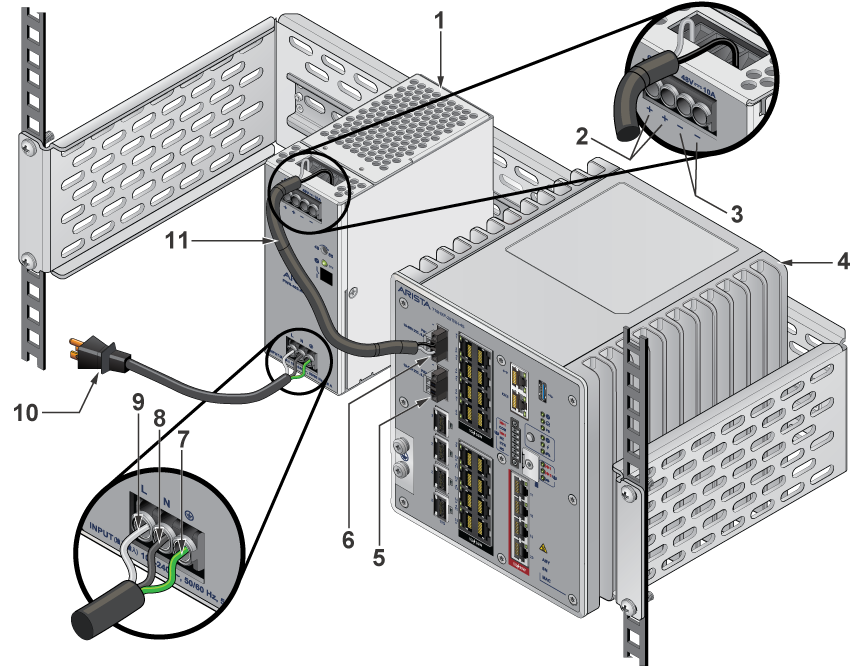
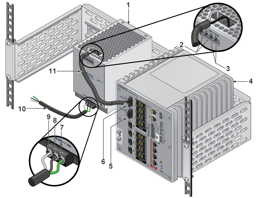
| 1 | AC PSU | 7 | Earth Ground |
| 2 | Positive Terminal | 8 | Neutral/Negative |
| 3 | Negative Terminal | 9 | Line/Positive |
| 4 | CCS-710HXP-20TNH-4S Device | 10 | AC Power Cord |
| 5 | PS2 DC Input | 11 | DC Interconnect Cable |
| 6 | PS1 DC Input |
| 1 | DC PSU | 7 | Earth Ground |
| 2 | Positive Terminal | 8 | Neutral/Negative |
| 3 | Negative Terminal | 9 | Line/Positive |
| 4 | CCS-710HXP-20TNH-4S Device | 10 | DC Power Cord |
| 5 | PS2 DC Input | 11 | DC Interconnect Cable |
| 6 | PS1 DC Input |
- Non-redundant: Connect power to either of the two power supplies.
- Redundant: Connect each DC power supply to a circuit that provides the required power.
Connecting Serial and Management Cables
This section describes the type of cables required to connect the device.
The following RJ-45 to DB-9 table lists the pin connections of the RJ-45 to DB-9 adapter cable.
| RJ-45 | DB-9 | RJ-45 | DB-9 | ||||
|---|---|---|---|---|---|---|---|
| RTS | 1 | 8 | CTS | GND | 5 | 5 | GND |
| DTR | 2 | 6 | DSR | RXD | 6 | 3 | TXD |
| TXD | 3 | 2 | RXD | DSR | 7 | 4 | DTR |
| GND | 4 | 5 | GND | CTS | 8 | 7 | RTS |
Connect the front panel ports as described below:
-
Console (Serial) Port: Connect to a computer with the RJ-45 to DB-9 serial adapter cable. The switch uses the following default settings:
- 9600 baud
- No flow control
- 1 stop bit
- No parity bits
- 8 data bits
- Ethernet Management Port: Connect to a 10/100/1000 management network with an RJ-45 Ethernet cable.
- USB Port: The USB port may be used for software or configuration updates.
Important:
Excessive bending can damage interface cables, especially optical cables.
Flexion excessive peut endommager les câbles d'interface, notamment des câbles optiques.