
Status Indicators
The Status Indicators section discusses the following topics:
Control Panel Indicators
Front panel LEDs are located on the upper right corner of the device for 1RU appliances.
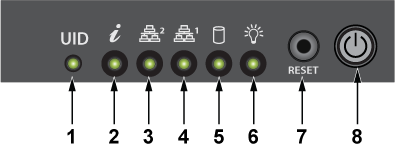
| 1 | UID LED | 2 | Information LED | 3 | NIC2 LED |
| 4 | NIC1 LED | 5 | HDD LED | 6 | Power LED |
| 7 | Reset button | 8 | Power button |
The front panel LEDs are located on the lower left corner of the device for the 2RU appliance.
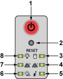
| 1 | Power button | 2 | Reset button | 3 | HDD LED |
| 4 | NIC1 LED | 5 | Information LED | 6 | Power fail LED |
| 7 | NIC2 LED | 8 | Power LED |
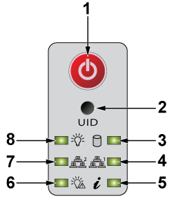
| 1 | Power button | 2 | UID button | 3 | Drive activity LED |
| 4 | NIC1 LED | 5 | Information LED | 6 | Power fail LED |
| 7 | NIC2 LED | 8 | Power LED |
Front Panel Status Indicators
The two LED indicators next to each hard drive carrier are activity and status indicators.
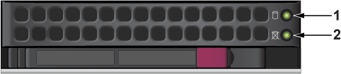
| Num | Label | Indication | Meaning |
|---|---|---|---|
| 1 | Storage Activity LEDs | Blinking | Actively transmitting or receiving data |
| Off | No transmit of data | ||
| 2 | NVMe Activity LEDs | Solid blue | Active connection |
| Off | No connection | ||
| 3 | Status | Off
Note: In non-RAID configurations, the status LEDs are always off.
|
Not in use |
DCA-NDR-S40
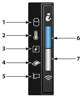
| Num | Label | Indication | Meaning |
|---|---|---|---|
| 1 | Drive indicator | Amber: Solid | Drive error |
| 2 | Temperature indicator | Amber: Solid | Thermal error |
| 3 | Electrical indicator | Amber: Solid | Electrical error |
| 4 | Memory indicator | Amber: Solid | Memory error |
| 5 | PCIe indicator | Amber: Solid | PCIe card error |
| 6 | System health and system ID indicator | Blue: Solid | System is powered on and healthy; but system ID mode is not active. |
| Blue: Blinking | System ID mode is active | ||
| Amber: Solid | System is in fail-safe mode | ||
| Amber: Blinking | System is experiencing a fault | ||
| 7 | IPMI Quick Sync 2 indicator | Off: Default state | IPMI Quick Sync 2 feature is powered off |
| White: Solid | IPMI Quick Sync 2 is ready to communicate | ||
| White: Blinks rapidly | Data transfer activity | ||
| White: Blinks slowly | Firmware update is in progress | ||
| White: Blinks 5 times rapidly and then powers off | The IPMI Quick Sync 2 feature is disabled | ||
| Amber: Solid | The system is in fail-safe mode | ||
| Amber: Blinking | IPMI Quick Sync 2 hardware is not responding properly. |
DCA-NDR-STR
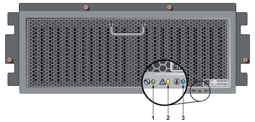
| Num | Label | Indication | Meaning |
|---|---|---|---|
| 1 | Power status LED | Green: Solid | Operational |
| 2 | System status LED | Amber: Blinking | Hardware fault |
| 3 | Enclosure ID | Blue: Blinking | Identifying enclosure |
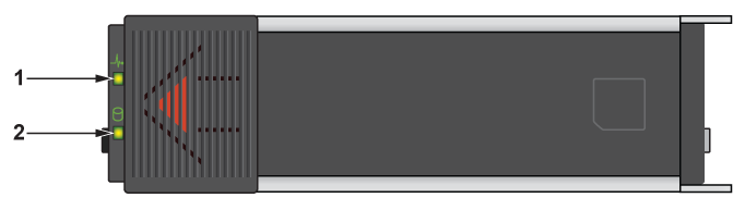
| Num | Label | Indication | Meaning |
|---|---|---|---|
| 1 | Drive activity LED | Green: Blinking |
|
| 2 | Drive status LED | Amber: Blinking |
|
DCA-NDR-NB10x
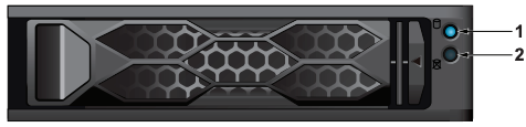
| Num | Label | Indication | Meaning |
|---|---|---|---|
| 1 | Activity LED | Blue - Blinking | Idle SAS/NVMe drive installed |
| Blue - Solid on | I/O activity | ||
| Off | Idle SATA or no drive installed | ||
| 2 | Status LED | Red - Solid on | Drive failure |
| Red - Blinking at 1 Hz | Rebuilding drive | ||
| Red - Blinking with two blinks and one stop at 1 Hz | Hot spare for drive | ||
| Red - On for five seconds, then of | Power on for drive | ||
| Red - Blinking at 4 Hz | Identifying drive | ||
| Green - Solid on | Safe to remove NVMe drive | ||
| Off | Idle SATA or no drive installed |
Rear Panel Status Indicators
The two LED indicators above either side of each management port and each packet capture port are link and activity indicators.
DCA-NDR-S100MB, DCA-NDR-S5, DCA-NDR-S10, DCA-NDR-A5 Packet Capture Port LEDs\
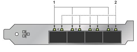
| Num | Label | Indication | Meaning |
|---|---|---|---|
| 1 | Link LEDs | Green | Linked at 10 Gb |
| Yellow | Linked at 1 Gb | ||
| 2 | Activity LEDs | Blinking | Actively transmitting or receiving data |
| Off | No link |
DCA-NDR-NB10/DCA-NDR-CC Interconnect Port LEDs
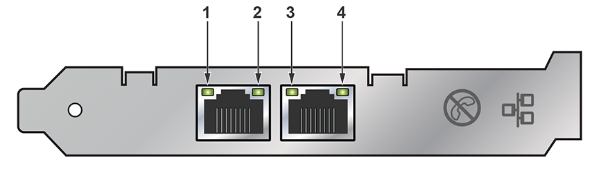
| Num | Label | Indication | Meaning |
|---|---|---|---|
| 1 | Link | Off | Not linked to the LAN |
| Green | Linked at 10 GB | ||
| Yellow | Linked at 1 GB | ||
| 2 | Activity | Off | No link |
| Blinking | Actively transmitting or receiving data |
Management Port LEDs
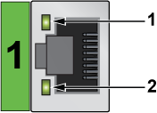
| 1 | Link LED | 2 | Activity LED |
| Num | Label | Indication | Meaning |
|---|---|---|---|
| 1 | Activity/Link | Green: Solid | The adapter is connected to a valid link partner. |
| Green: Flashing | Data activity | ||
| Off | No link | ||
| 2 | 10 = Off
100 = Green 1000 = Yellow |
Off | 10 Mbps |
| Green | 100 Mbps | ||
| Yellow | 1000 Mbps |
IPMI Ethernet Port LEDs
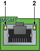
| 1 | Link LED | 2 | Activity LED |
The green, amber, or off indicates the speed of the connection. The amber LED indicates activity.
| LED Color | Definition |
|---|---|
| Amber: Solid | 1 Gb/s |
| Green: Solid | 100 Mb/s |
| Off | No connection or 10 Mb/s |
DCA-NDR-S40
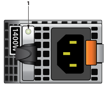
| Num | Label | Indication | Meaning |
|---|---|---|---|
| 1 | AC PSU status indicator | Green | A valid power source is connected to the PSU and the PSU is operational |
| Amber: Blinking | An issue with the PSU | ||
| Powered off | The power is not connected to the PSU | ||
| Green: Blinking | The firmware of the PSU is being updated | ||
| Blinking green and powers off | When hot-plugging a PSU, it blinks green five times at a rate of 4 Hz and powers off. This indicates a PSU mismatch due to efficiency, feature set, health status, or supported voltage. |
DCA-NDR-STR
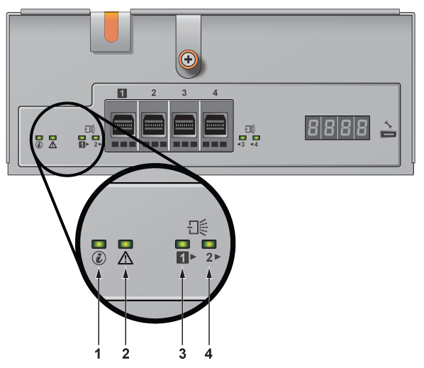
| Num | Label | Indication | Meaning |
|---|---|---|---|
| 1 | EMM ID | Blue |
|
| 2 | EMM Status | Solid Green | Normal operation |
| Blinking Amber | EMM failure - On for two seconds and off for one second. | ||
| 3 | Mini-SAS HD status for Mini-SAS HD ports 1 | Green |
|
| Amber |
|
||
| 4 | Mini-SAS HD status for Mini-SAS HD ports 2 | Green |
|
| Amber |
|
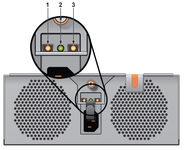
| Num | Label | Indication | Meaning |
|---|---|---|---|
| 1 | DC Power output | Green |
|
| 2 | AC Power input | Green |
|
| 3 | PSU fault | Amber |
|
DCA-NDR-NB10x
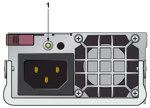
| Num | Label | Indication | Meaning |
|---|---|---|---|
| 1 | Power supply LED | Green - Solid on | Power supply is on |
| Green - Blinking | Power supply is plugged in and turned off by the system | ||
| Amber - Solid on | Power supply has a warning condition and continues to operate | ||
| Amber - Blinking | Power supply is plugged in, and is in an abnormal state. The system might need service. Please contact Supermicro technical support. | ||
| Off | No AC power to modules |
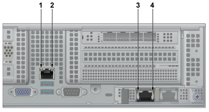
| Num | Label | Indication | Meaning |
|---|---|---|---|
| 1 | IPMI LAN port - Link LED | Amber - Solid on | A valid 1 Gbps connection is active |
| Green - Solid on | A valid 100 Mbps connection is active | ||
| Off | No link established, or the cable is not plugged in | ||
| 2 | IPMI LAN port - Activity LED | Yellow - Solid on / Blinking | Data is actively transmitting or receiving through the port |
| Off | No data traffic | ||
| 3 | Management port - Link LED | Green - Solid on | A valid 10 Gbps connection is active |
| Amber - Solid on | A valid 100 Mbps connection is active | ||
| 4 | Management port - Activity LED | Green - Solid on | Connection is established |
| Green - Blinking | Data is actively transmitting or receiving through the port | ||
| Off | No data traffic |