Advanced Policy Configuration
This chapter describes advanced features and use cases for DANZ Monitoring Fabric (DMF) policies.
Advanced Match Rules
Error: Unexpected additional arguments ...
Match Fields and Criteria
The following summarizes the different match criteria available:
- src-ip, dst-ip, src-mac, and dst-mac are maskable. If the mask for src-ip, dst-ip, src-mac, or dst-mac is not specified, it is assumed to be an exact match.
- For src-ip and dst-ip, specify the mask in either CIDR notation (for example, /24) or dotted-decimal notation (255.255.255.0).
- For src-ip and dst-ip, the mask must be contiguous. For example, a mask of 255.0.0.255 or 0.0.255.255 is not supported.
- For TCP, the tcp-flags option allows a match on the following TCP flags: URG, ACK, PSH, RST, SYN, and FIN.
- src-ip-range and dst-ip-range
- src-ip address group and dst-ip address group
- ip-range and ip address group
DANZ Monitoring Fabric (DMF) supports matching on user-defined L3/L4 offsets instead of matching on these criteria. However, it is not possible to use both matching packet methods in the same DMF. Switching between these match modes may cause policies defined under the previous mode to fail.
Apply match rules to the following fields in the packet header:
dscp-value Match on DSCP value. Value range is 0..63
dst-ip Match dst ip
dst-port Match dst port
is-fragment Match if the packet is IP fragmented
is-not-fragment Match if the packet is not IP fragmented
l3-offset Match on l3 offset
l4-offset Match on l4 offset
range-dst-ip Match dst-ip range
range-dst-port Match dst port ramge
range-src-ip Match src-ip range
range-src-port Match src port range
src-ip Match src ip
src-port Match src port
untagged Untagged (no vlan tag)
vlan-id Match vlan-id
vlan-id-range Match vlan-id range
<ip-proto> IP Protocol
1 match ip src-ip 1.1.1.1 255.255.255.255 dst-ip 2.2.2.2 255.255.255.255
1 match ip src-ip 1.1.1.1 255.255.255.255
2 match ip dst-ip 2.2.2.2 255.255.255.255
controller-1(config)# policy dmf-policy-1
controller-1(config-policy)# 10 match any
1 match tcp tcp-flags 2 2
2 match tcp tcp-flags 18 18
Match-except Rules
- Match-except only supports IPv4 source-IP and IPv4 destination-IP match fields.
- Example - Permit src-ip network, except ip-address:
1 match ip src-ip 172.16.0.0/16 except-src-ip 172.16.0.1
- Example - Permit dst-ip network, except subnet
1 match ip dst-ip 172.16.0.0/16 except-dst-ip 172.16.128.0/17
- Example - Permit src-ip network, except ip-address:
- In a rule, the except condition can only be used with either src-ip or dst-ip, but not with src-ip and dst-ip together.
- Example - Except being used with src-ip:
1 match icmp src-ip 172.16.0.0/16 except-src-ip 172.16.0.1 dst-ip 172.16.0.0/16
- Example - Except being used with dst-ip:
1 match icmp src-ip 224.248.0.0/24 dst-ip 172.16.0.0/16 except-dst-ip 172.16.0.0/18
- Example - Except being used with src-ip:
- Except-src-ip or except-dst-ip can only be used after a match for src-ip or dst-ip, respectively.
- Example - Incorrect match rule:
1 match icmp except-src-ip 192.168.1.10
- Example - Correct match rule:
1 match icmp src-ip 192.168.1.0/24 except-src-ip 192.168.1.10
- Example - Incorrect match rule:
- In a match rule, only one IP address, or one subnet (range of IP addresses) can be used with the
exceptcommand.- Example - Deny a subnet:
1 match ip dst-ip 172.16.0.0/16 except-dst-ip 172.16.0.0/18
- Example - Deny an IP Address:
1 match ip dst-ip 172.16.0.0/16 except-dst-ip 172.16.0.1
- Example - Deny a subnet:
Matching with IPv6 Addresses
The value of the EtherType field determines whether the src-ip field to match is IPv4 or IPv6. The DANZ Monitoring Fabric (DMF) Controller displays an error if there is a mismatch between the EtherType and the IP address format.
- The preferred IPv6 address representation is as follows: xxxx:xxxx:xxxx:xxxx:xxxx:xxxx:xxxx:xxxx, where each x is a hexadecimal digit representing 4 bits.
- IPv6 addresses range from 0000:0000:0000:0000:0000:0000:0000:0000 to ffff:ffff:ffff:ffff:ffff:ffff:ffff.
In addition to this preferred format, IPv6 addresses may be specified in two other shortened formats:
- Omit Leading Zeros: Specify IPv6 addresses by omitting leading zeros. For example, write IPv6 address 1050:0000:0000:0000:0005:0600:300c:326b as 1050:0:0:0:5:600:300c:326b.
- Double Colon: Specify IPv6 addresses using double colons (::) instead of a series of zeros. For example, write IPv6 address ff06:0:0:0:0:0:0:c3 as ff06::c3. Double colons may be used only once in an IP address.
DMF does not support the IPv4 address embedded in the IPv6 address format. For example, neither 0:0:0:0:0:0:101.45.75.219 nor ::101.45.75.219 can be used.
Both IPv4 and IPv6 masks must be in CIDR format. For example, FFFF:FFFF:FFFF:FFFF:0:0:0:0 is valid in DMF, but FFFF:0:0:FFFF:FFFF:0:0:0:0 is not a valid mask.
controller-1(config)# policy dmf-ipv6-policy
controller-1(config-policy)# 10 match ip6 src-ip 2001::0 ffff:ffff:ffff:ffff:0:0:0:0
controller-1(config-policy)# 11 match ip6 dst-ip 2001:db8:122:344::/64
controller-1(config-policy)# filter-interface all
controller-1(config-policy)# action drop
Port and VLAN Range Matches
- range-dst-ip: Match dst-ip range.
- range-dst-port: Match dst port range.
- range-src-ip: Match src-ip range.
- range-src-port: Match src port range.
controller-1(config)# policy ip-port-range-policy
controller-1(config-policy)# 10 match tcp range-src-port 10 100
controller-1(config-policy)# 15 match udp range-dst-port 300 400
controller-1(config-policy)# 20 match tcp range-src-port 10 2000 range-dst-port 400 800
controller-1(config-policy)# 30 match tcp6 range-src-port 8 20
controller-1(config-policy)# 40 match tcp6 range-src-ip 1:2:3:4::/64 range-src-port 10 300
controller-1(config-policy)# filter-interface all
controller-1(config-policy)# delivery-interface all
controller-1(config-policy)# action forward
controller-1(config)# policy vlan-range-policy
controller-1(config-policy)# 10 match mac vlan-id-range 30 400
controller-1(config-policy)# 20 match full ether-type ip protocol 6 vlan-id-range 1000 3000 srcip 1.
1.1.1 255.255.255.255 src-port-range 100 500
controller-1(config-policy)# show running-config policy
! policy
policy vlan-range-policy
action forward
delivery-interface TOOL-PORT-1
filter-interface TAP-PORT-1
10 match mac vlan-id-range 12 99
controller-1(config-policy)# show policy vlan-range-policy optimized-match
Optimized Matches :
10 vlan-min 12 vlan-max 15
10 vlan-min 16 vlan-max 31
10 vlan-min 32 vlan-max 63
10 vlan-min 64 vlan-max 95
10 vlan-min 96 vlan-max 99
User Defined Filters
Selecting the User Defined Offsets option when the L3-L4 Offset Match switching mode is not enabled, the system displays a message to enable the correct match mode.
- Anchor: Specified from where the user can define the matching criteria. There are three options: a) L3-start: Start of layer 3 header. b) L4-start: Start of layer 4 header. c) Packet-start: Start of the packet from layer 2 header.
- Offset: The number of bytes from the specified anchor.
- Length: The number of matching bytes, either 2 or 4 bytes.
- Value: The matching value of the specified length in hexadecimal, decimal, or IPv4 format.
- Mask: The value that is ANDed with the match value.
Configure each switch with a maximum of eight different offsets matching two bytes each, used in a single policy or any combination in different policies. In the example below, the policy matches on a value of 0x00001000 at offset 40 from the start of the L3-header and a value of 0x00002000 at offset 64 from the start of the L4-header.
controller-1(config-policy)# 1 match udp dst-port 2152 l3-offset 40 length 4 value 0x00001000 mask
0xffffffff l4-offset 64 length 4 value 0x00002000 mask 0xffffffff
show user-defined-offset command to display the values configured in the user-defined-offset table.
controller-1# show user-defined-offset
# Switch         Slot Anchor   Offset Length Policy
-|--------------|----|--------|------|------|-------------------------------------------------------|
1 DMF-FILTER-SW1 0    l4-start 64     2      DMF-UDF-TEST-1, _DMF-UDF-TEST-1_o_SAVE-TO-RECORDER-NODE
2 DMF-FILTER-SW1 1    l4-start 66     2      DMF-UDF-TEST-1, _DMF-UDF-TEST-1_o_SAVE-TO-RECORDER-NODE
3 DMF-FILTER-SW1 2    l3-start 40     2      DMF-UDF-TEST-1, _DMF-UDF-TEST-1_o_SAVE-TO-RECORDER-NODE
4 DMF-FILTER-SW1 3    l3-start 42     2      DMF-UDF-TEST-1, _DMF-UDF-TEST-1_o_SAVE-TO-RECORDER-NODE
controller-1#
| UDF Features | Non-Trident SWL Switch | Trident 3 SWL Switch | EOS Switches |
|---|---|---|---|
| Total UDF Length | 16 bytes | 12 bytes | 12 bytes |
| Minimum Chunk Size | 2 bytes | 2 bytes | 2 bytes |
| Packet Start (Layer 2 Anchor) | 8 offsets | 2 offsets | 6 offsets |
| Layer 3 Anchor | 8 offsets | 6 offsets | 6 offsets |
| Layer 4 Anchor | 8 offsets | 6 offsets | 6 offsets |
| Layer 2 Offset Range | 0 - 126 bytes | 0 - 62 bytes | 0 - 126 bytes |
| Layer 3 Offset Range | 0 - 114 bytes | 0 - 112 bytes | 0 - 114 bytes |
| Layer 4 Offset Range | 0 - 96 bytes | 0 - 112 bytes | 0 - 96 bytes |
Filter and Delivery Role with MAC Loopback for a Two-stage Policy
Use the Filter and Delivery role with a MAC (software) loopback to support monitoring as a service. This option uses a two-stage policy to replicate the incoming feed from one or more filter interfaces and send it to multiple intermediate interfaces (one per end customer or organization).
Define policies on the intermediate interface for forwarding to customer-specific tools. These intermediate interfaces must also be assigned the Filter and Delivery role enabled with the MAC loopback option. This method eliminates the need for a physical loopback cable and a second interface, simplifying monitoring deployment as a service.
When multiple user-defined policies with overlapping rules select traffic from the same filter interfaces for forwarding to different delivery interfaces, overlapping policies are automatically generated to replicate the requisite traffic to the delivery interfaces. The number of overlapping policies increases exponentially with the number of user-defined policies.
Switch hardware limits limit the total number of policies in the fabric. Using a Filter and Delivery role with a MAC loopback can also help eliminate scale and operational issues seen with overlapping policies.
To configure an interface with the Filter and Delivery role and enable the MAC (software) loopback option, use the loopback-mode mac command to assign an unused interface as a loopback. This command enables the physical interface without requiring a physical connection to the interface. Use a software loopback interface for copying traffic in any scenario where a physical loopback is required.
The user can also assign the Filter and Delivery role to a software loopback interface, which allows the use of a single interface for copying traffic to multiple destination interfaces. When assigning this role to an interface in loopback mode, use the interface as a delivery interface in relation to the original filter interface and as a filter interface in relation to the final destination interface.
The following figure illustrates the physical configuration for a switch that uses four software loopback interfaces to copy traffic from a single filter interface to four different tools:
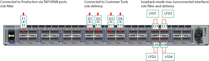
Use this configuration to copy different types of traffic from a single filter interface (F1) to four delivery interfaces (D1 to D4). Assign the Filter and Delivery role to the software loopback interfaces (LFD1 through LFD4) using just four physical interfaces. Physical loopbacks would require twice as many interfaces.
Considerations
- The SFP decides the Mac loopback speed. DMF uses the max port speed if there is no SFP (i.e., an empty port).
- The port speed configuration (if any) will not impact the Mac loopback speed. The Mac loopback speed is set based on the SFP or the max port speed if there is no SFP.
- The Rate-limit option limits the Mac loopback traffic at Rx side.
Configure Filter and Delivery Interfaces with MAC Loopback
To configure an interface with the Filter and Delivery role and enable the MAC (software) loopback option, perform the following steps:
- Display the available interfaces by selecting .
The system displays the Interfaces page, which lists the interfaces connected to the DANZ Monitoring Fabric (DMF) fabric.
Figure 2. Fabric Interfaces 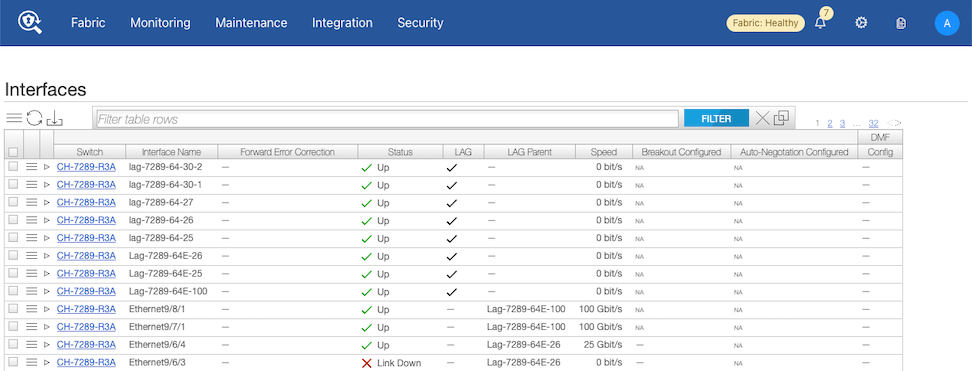
- Select the Menu control for the interface to use and select Configure from the pull-down menu.
The system displays the following dialog:
Figure 3. Fabric > Interfaces > Edit Interface > Port 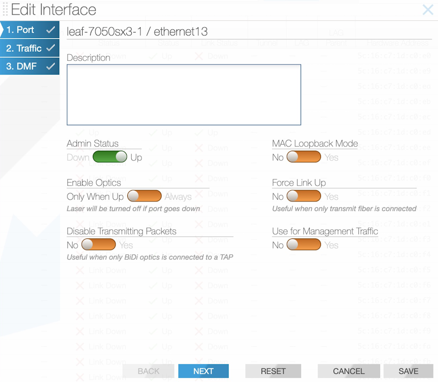
- Select Next.
Figure 4. Fabric > Interfaces > Edit Interface > Traffic 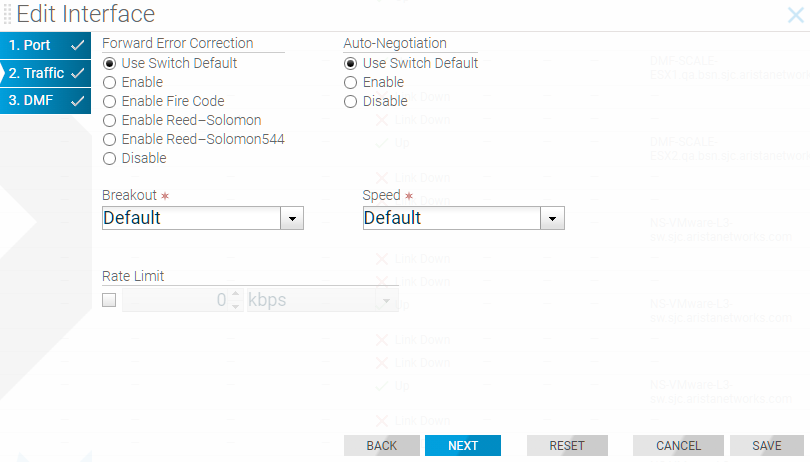
- (Optional) Configure Rate Limiting, if required, and select Next.
Figure 5. Fabric > Interfaces > Edit Interface > DMF 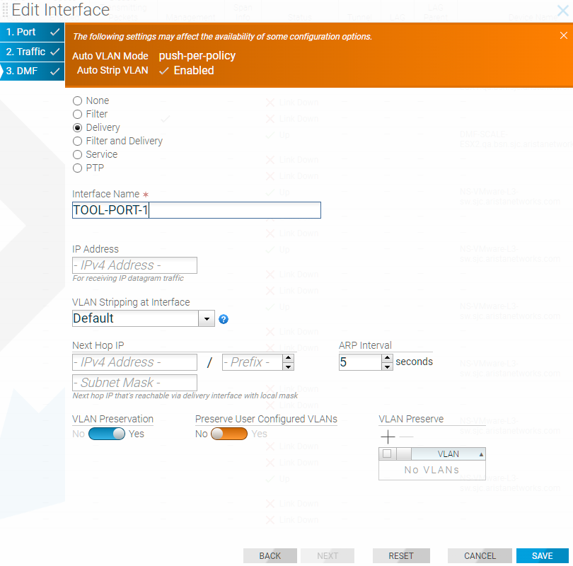
Using the CLI To Configure a Filter and Delivery Interface with MAC Loopback
switch DMF-FILTER-SWITCH-1
admin hashed-password
$6$5niT1gPm$Jc24qOMF.hxNPI20DvnKaFZKYD6lIo59IMp3O4xIdwVTu2hx0s8Djpvz9xXAXXndiSkKe5jH.9PKoHHrWviSl0
mac 70:72:cf:dc:99:5c
interface ethernet1
role filter interface-name TAP-PORT-1
interface ethernet13
role delivery interface-name TOOL-PORT-1
interface ethernet15
role delivery interface-name TOOL-PORT-1
interface ethernet17
role delivery interface-name TOOL-PORT-3
interface ethernet19
role delivery interface-name TOOL-PORT-4
interface ethernet25
loopback-mode mac
role both-filter-and-delivery interface-name LOOPBACK-PORT-1
interface ethernet26
loopback-mode mac
role both-filter-and-delivery interface-name LOOPBACK-PORT-2
interface ethernet27
loopback-mode mac
role both-filter-and-delivery interface-name LOOPBACK-PORT-3
interface ethernet28
loopback-mode mac
role both-filter-and-delivery interface-name LOOPBACK-PORT-4
! policy
policy TAP-NETWORK-1
action forward
delivery-interface LOOPBACK-PORT-1
delivery-interface LOOPBACK-PORT-2
delivery-interface LOOPBACK-PORT-3
delivery-interface LOOPBACK-PORT-4
filter-interface TAP-PORT-1
1 match any
!
policy DUPLICATED-TRAFFIC-1
action forward
delivery-interface TOOL-PORT-1
filter-interface LOOPBACK-PORT-1
1 match ip src-ip 100.1.1.1 255.255.255.252
!
policy DUPLICATED-TRAFFIC-2
action forward
delivery-interface TOOL-PORT-2
filter-interface LOOPBACK-PORT-2
1 match ip dst-ip 100.1.1.1 255.255.255.252
!
policy DUPLICATED-TRAFFIC-3
action forward
delivery-interface TOOL-PORT-3
filter-interface LOOPBACK-PORT-3
1 match tcp src-port 1234
!
policy DUPLICATED-TRAFFIC-4
action forward
delivery-interface TOOL-PORT-4
filter-interface LOOPBACK-PORT-4
1 match tcp dst-port 80
Use the show policy command to verify the policy configuration.
Rate Limiting Traffic to Delivery Interfaces
The option exists to limit the traffic rate on a delivery interface, which can be a regular interface, a port channel, a tunnel interface, or a loopback interface.
For information about using rate limiting on tunnels, refer to the section Using the CLI to Rate Limit the Packets on a VXLAN Tunnel.
Use kbps to configure the rate-limit for the regular delivery interface. Arista Networks recommends configuring the rate limit in multiples of 64 kbps.
Rate Limiting Using the GUI
- Select .
Figure 6. Delivery Interfaces 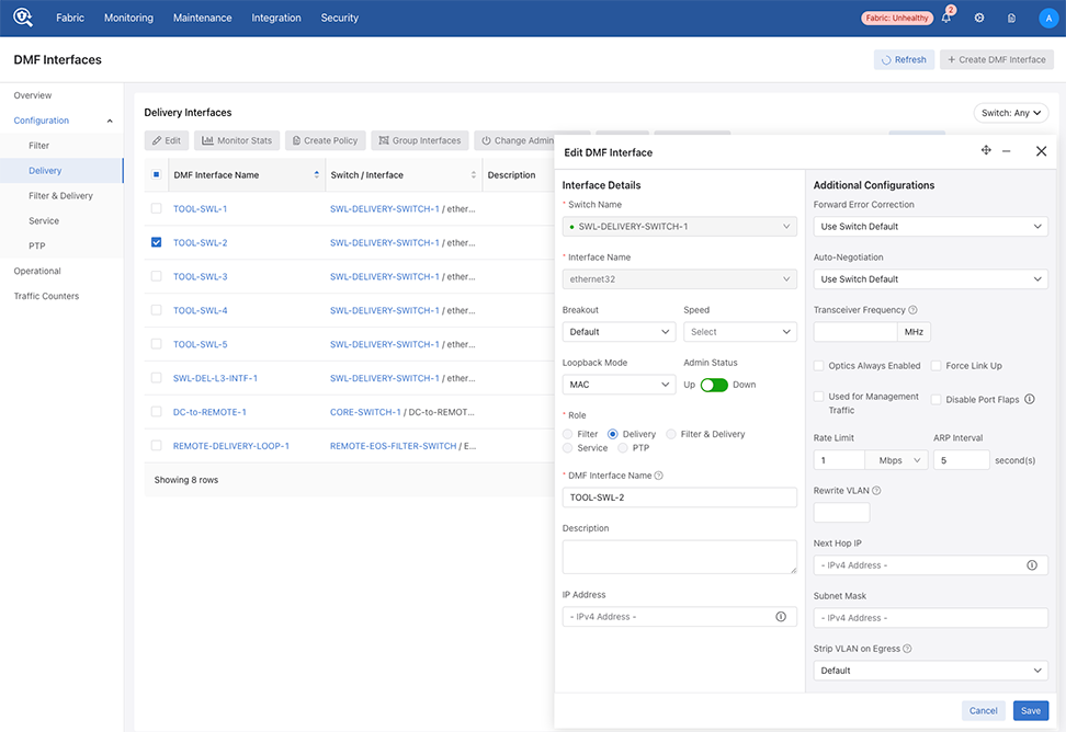
- Select a Rate Limit number and the Bit Rate from the drop-down.
Figure 7. Setting the Rate Limit for an Interface 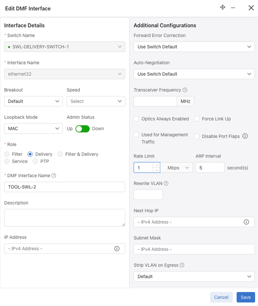
Rate Limiting Using the CLI
CLI Procedure
interface
tobcotDelivery
:
CONTROLLER-1(config)#switch DMF-DELIVERY-SWITCH-1
CONTROLLER-1(config-switch)# interface ethernet1
CONTROLLER-1(config-switch-if)# role delivery interface-name TOOL-PORT-1
CONTROLLER-1(config-switch-if)# rate-limit 10240
CONTROLLER-1(config-switch-if)# show this
! switch
switch DMF-DELIVERY-SWITCH-1
!
interface ethernet1
rate-limit 10000
role delivery interface-name TOOL-PORT-1
CONTROLLER-1 (config-switch-if)#
lag-interface lag1
hash-type l3
member ethernet43
member ethernet45
interface ethernet43
rate-limit 10000 <------ set the rate-limit to 10 Mbps
interface ethernet45
rate-limit 128000 <---------- set the rate-limit to 128 Mbps
Configuring Overlapping Policies

In the policy illustrated, packets received on interface Filter 1 with the source-IP address 10.1.1.x/24 are delivered to D1. In a separate policy, with the same priority, packets received at Filter 1 with the destination IP address 20.1.1.y/24 are delivered to D2. With both these policies applied, when a packet arrives at F1 with a source IP address 10.1.1.5/24 and a destination IP address 20.1.1.5/24, the packets are copied and forwarded to both D1 and D2. Enabled by default, the DANZ Monitoring Fabric (DMF) policy overlap feature causes this behavior.
DMF manages overlapping policies automatically by copying packets received on the same filter interface that match multiple rules but which the policy forwards to different delivery interfaces.
- Both policies have the same configured priority (or the same default priority).
- At least one filter interface is shared.
- At least one match rule in one policy intersects with at least one match rule in the other policy, which occurs when it is possible for a single packet to match both conditions simultaneously. For example, a rule matching src-ip 10.0.0.1 range-src-port 10 20 intersects with a rule matching dst-ip 10.0.0.2 range-src-port 15 25, since a packet could satisfy both rules (when the src-port is between 15 and 20, the src-ip is 10.0.0.1, and the dst-ip is 10.0.0.2).
- Either component policy is already in an error state.
- Either component policy has an action drop.
- The number of overlapping policies sharing the same filter interface at the same priority exceeds the configured overlap limit.
- The number of match rules required to cover the overlap between the two policies exactly exceeds the maximum allowed per policy.
- Both policies use the same non-L3 managed service instance, but with different configurations (e.g., one marks it optional and the other does not).
- Creates a new dynamic policy that aggregates the policy actions.
- Assigns policy names, using this dynamic policy naming convention: _policy1_o_policy2_
- Adds match combinations and configuration as appropriate.
- Assigns a slightly higher priority to the new aggregated policy so that it overrules the overlapping policies, which, as a result, only applies to traffic that does not match the new aggregated policy. An incremental value of .1 is added to the original policy priority. For example, if the original policies have a priority of 100, the dynamic policy priority is 101.
Note: When changing the configurable parameters in an existing DMF out-of-band policy, any counters associated with the policy, including service-node-managed services counters, are reset to zero.
Configuring the Policy Overlap Limit Using the GUI
Perform the following steps to configure the Policy Overlap Limit.
- Control the configuration of this feature using Edit by locating the corresponding card and selecting the pencil icon.
Figure 9. Policy Overlap Limit 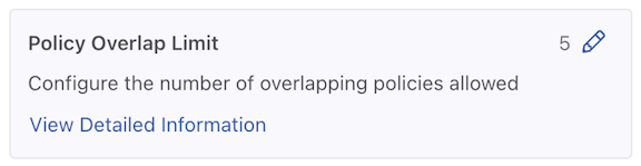
- A configuration edit dialogue window pops up, displaying the corresponding prompt message. By default, the Policy Overlap Limit is 4.
Figure 10. Edit Policy Overlap Limit 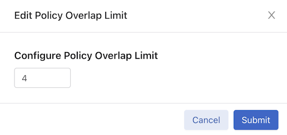
- After successfully setting the configuration, the current configuration status displays next to the Pencil (edit) icon.
Figure 11. Policy Overlap Limit Change Success 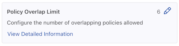
Configuring the Overlapping Policy Limit Using the CLI
By default, the number of overlapping policies allowed is four. The maximum number to configure for overlapping policies is ten. Set the overlap policy limit to zero to disable the overlapping policy feature.
controller-1(config)# overlap-policy-limit integer
Replace integer with the maximum number of overlapping policies to support fabric-wide.
controller-1(config)# overlap-policy-limit 10
controller-1(config)# overlap-policy-limit 0
Using the CLI to View Overlapping Policies
show policy command to view statistics for dynamic (overlapping) policies. If an overlapping policy appears in the output, the parent policies are identified, as in the following example:
controller-1(config-policy)# show policy
# Policy Name Config Status         Runtime Status Action  Type       Priority Overlap Priority Rewrite VLAN Filter BW Delivery BW Services
-|-----------|---------------------|--------------|-------|----------|--------|----------------|------------|---------|-----------|--------|
1 _p2_o_p1    active and forwarding installed      forward Dynamic    100      1                0            -         -
2 p1          active and forwarding installed      forward Configured 100      0                0            -         -
3 p2          active and forwarding installed      forward Configured 100      0                0            -         -
- show overlap _P1_O_P2, lists component policies: source P1, P2.
- show P1, lists dynamic policies: overlap _P1_O_P2.
controller-1(config-policy)# show policy _p1_o_p2
Policy Name : _p1_o_p2
Config Status : active and forwarding
Runtime Status : installed
Detailed Status : installed - installed to forward
Action : forward
Priority : 100
Overlap Priority : 1
Description : runtime policy
# of switches with filter interfaces : 1
# of switches with delivery interfaces : 1
# of switches with service interfaces : 0
# of filter interfaces : 1
# of delivery interfaces : 2
# of core interfaces : 4
# of services : 0
# of pre service interfaces : 0
# of post service interfaces : 0
Rewrite VLAN : 0
Total Ingress Rate : -
Total Delivery Rate : -
Total Pre Service Rate : -
Total Post Service Rate : -
Overlapping Policies : none
Component Policies : p2, p1,
Failed Overlap Policy Exceeding Max Rules :
Rewrite valid? : False
Service Names :
Overlap Matches :
1 ether-type 2048 src-ip 10.1.1.1 255.255.255.0 dst-ip 20.1.1.1 255.255.255.0
Strip VLAN : False
Delivery Bandwidth : 20 Gbps
explicitly-scheduled : False
Filter Bandwidth : 10 Gbps
Type : Dynamic
~ Match Rules ~
None.
~~~~~~~~~~~~~~~~~~~~~~~~~~~ Filter Interface(s) ~~~~~~~~~~~~~~~~~~~~~~~~~~~
# IF Switch IF Name State Dir Packets Bytes Pkt Rate Bit Rate
-|---------|-----------|--------|-----|---|-------|-----|--------|--------|
1 f1 filter-sw-1 s11-eth1 up rx 0 0 0 -
~~~~~~~~~~~~~~~~~~~~~~~~~~ Delivery Interface(s) ~~~~~~~~~~~~~~~~~~~~~~~~~~
# IF Switch IF Name State Dir Packets Bytes Pkt Rate Bit Rate
-|---------|-----------|--------|-----|---|-------|-----|--------|--------|
1 d1 filter-sw-2 s12-eth1 up tx 0 0 0 -
2 d2 filter-sw-2 s12-eth2 up tx 0 0 0 -
~ Service(s) ~
None.
~~~~~~~~~~~~~~~~~~~~~~~ Core Interface(s) ~~~~~~~~~~~~~~~~~~~~~~~
# Switch IF State Dir Packets Bytes Pkt Rate Bit Rate
-|-----------|--------|-----|---|-------|-----|--------|--------|
1 filter-sw-1 s11-eth3 up tx 0 0 0 -
2 core-sw-2 s10-eth1 up rx 0 0 0 -
3 core-sw-2 s10-eth2 up tx 0 0 0 -
~ Failed Path(s) ~
None.
~~~~~~~~~~~~~~~~~~~~~~~~~~~~~~~~~~~~ Event History ~~~~~~~~~~~~~~~~~~~~~~~~~~~~~~~~~~~~
# Time Event Detail
-|-------------------|---------------------|-------------------------------------------|
1 2014-08-05 22:22:27 start forward pending installation - installed to forward
2 2014-08-05 22:22:27 installation complete installed - installed to forward
Configuring the Policy Overlap Limit Strict using the GUI
From the DANZ Monitoring Fabric (DMF) Features page, proceed to the Configuring the Policy Overlap Limit Strict feature card.
- Select the Policy Overlap Limit Strict card.
Note: The Policy Overlap Limit Strict option is enabled by default. The following steps guide if the Policy Overlap Limit Strict option is disabled.
Figure 12. Policy Overlap Limit Strict Disabled 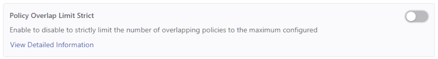
- Confirm the activation by selecting Enable. Or, Cancel to return to the DMF Features page.
Figure 13. Enable Policy Overlap Limit Strict 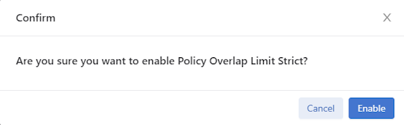
- Retain Configuring the Policy Overlap Limit Strict is running.
Figure 14. Policy Overlap Limit Strict Enabled 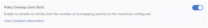
- To disable the feature, toggle the Policy Overlap Limit Strict switch to Off. Select Disable and confirm.
Figure 15. Disable Policy Overlap Limit Strict  The feature card updates with the status.
Figure 16. Policy Overlap Limit Strict Disabled
Configuring the Policy Overlap Limit Strict using the CLI
The Policy Overlap Limit Strict option, enabled by default, strictly limits the number of overlapping policies to the maximum configured. For example, when setting the maximum number of overlapping policies to 4 (the default) and users create a fifth policy using the same filter interface, the operation fails with a validation error.
controller-1(config)# no overlap-limit-strict
controller-1(config)# overlap-limit-strict
Exclude Inactive Policies from Overlap Limit Calculation
Suppose the limit is 4, and a user attempts to create a 5th policy using the same filter interface (f1). DMF throws the following error message: Error: Validation failed: Filter interfaces used in more than 4 policies: f1.
active or inactive policies.
The DMF policy overlap calculation excludes inactive policies when using the inactive command in policy configuration. For example, using the same policy limit settings described above, DMF supports creating a 5th policy using the same filter interface (f1) by first putting the 5th policy in an inactive state using the inactive command under policy configuration.
Show Commands
The following command example displays the configured policies listing two overlap policies _p1_o_p2.
(config-policy)# show policy
# Policy Name Action  Runtime Status               Type       Priority Overlap Priority Push VLAN Filter BW (truncated...)
-|-----------|-------|----------------------------|----------|--------|----------------|---------|--------- (truncated...)
1 _p1_o_p2    forward A component policy failed    Dynamic    100      1                3         10Gbps    (truncated...)
2 p1          forward all delivery interfaces down Configured 100      0                1         10Gbps    (truncated...)
3 p2          forward all delivery interfaces down Configured 100      0                2         10Gbps    (truncated...)
4 p3          forward inactive                     Configured 100      0                4         -         (truncated...)
To add filter interface f1 to the third overlap policy, p3, set the policy to inactive.
(config-switch)# policy p3
(config-policy)# inactive
(config-policy)# filter-interface f1
This results in an inactive policy p3 being configured with filter interface f1. Use the show
running-config policy command to view the status.
(config-policy)# show running-config policy
! policy
policy p1
action forward
delivery-interface d1
filter-interface f1
1 match any

policy p2
action forward
delivery-interface d2
filter-interface f1
1 match any

policy p3
action forward
delivery-interface d3
filter-interface f1
inactive
1 match any
Exclude Expired Policies from Overlap Limit Calculation
If any two policies use the same filter interface and the same priority, then an additional dynamic policy is created to ensure the delivery of packets matching both of the original policies. There is a limit on how many overlap policies can be created and it is configurable with a range between 0 to 10 with a default value of 4. Currently, the system excludes policies configured as inactive in the overlap policy limit calculation. With this new feature, the system excludes policies that have an expired duration from the overlap policies limit calculation.
CLI Configuration
No new configuration is necessary to use this feature. However, In order to achieve this improvement, the existing config validation Filter interfaces
used in more than n policies was removed which is present in the policy creation of adding the filter interface after exceeding the max overlap limit number of policies.
Show Commands
Once the number of installed overlap policies reaches the maximum limit, any additional policies will not be installed. They are marked as inactive with the reason: Filter interface fil1 cannot be used in more than 2 active
policies. In the example below, the overlap limit is 2.
controller-1# show running-config overlap-policy-limit

! overlap-policy-limit
overlap-policy-limit 2
policy1, policy2 and its overlap policy _policy1_o_policy2 have been installed. Since the overlap policy limit has been reached, policy policy3 is inactive.
# Policy Name        Action  Runtime Status Type       Priority Overlap Priority Push VLAN Filter BW Delivery BW Post Match Filter Traffic Delivery Traffic Services Installed Time          Installed Duration Ptp Timestamping
-|------------------|-------|--------------|----------|--------|----------------|---------|---------|-----------|-------------------------|----------------|--------|-----------------------|------------------|----------------|
1 _policy1_o_policy2 forward installed      Dynamic    100      1                3         10Gbps    20Gbps      -                         -                         2025-06-30 06:55:00 UTC 13 secs            False
2 policy1            forward installed      Configured 100      0                2         10Gbps    10Gbps      -                         -                         2025-06-30 06:55:00 UTC 13 secs            False
3 policy2            forward installed      Configured 100      0                1         10Gbps    10Gbps      -                         -                         2025-06-30 06:55:00 UTC 13 secs            False
4 policy3            forward inactive       Configured 100      0                4         10Gbps    10Gbps      -                         -                                                                    False
policy3 inactive is shown in both the Config Status and Detailed
Status.
controller-1# show policy policy3
Policy Name                            : policy3
Config Status                          : Filter interface fil1 cannot be used in more than 2 active policies
Runtime Status                         : inactive
Detailed Status                        : Filter interface fil1 cannot be used in more than 2 active policies
Priority                               : 100
Overlap Priority                       : 0
# of switches with filter interfaces   : 1
# of switches with delivery interfaces : 1
# of switches with service interfaces  : 0
# of filter interfaces                 : 1
# of delivery interfaces               : 1
# of core interfaces                   : 0
# of services                          : 0
# of pre service interfaces            : 0
# of post service interfaces           : 0
Push VLAN                              : 4
Post Match Filter Traffic              : -
Total Delivery Rate                    : -
Total Pre Service Rate                 : -
Total Post Service Rate                : -
Overlapping Policies                   : none
Component Policies                     : none
Timestamping enabled                   : False
~ Match Rules ~
# Rule
-|-----------|
1 1 match any

~~~~~~~~~~~~~~~~~~~~~~~~~~~~~~~~~~ Filter Interface(s) ~~~~~~~~~~~~~~~~~~~~~~~~~~~~~~~~~~
# DMF IF Switch  IF Name    State Dir Packets Bytes Pkt Rate Bit Rate Counter Reset Time
-|------|-------|----------|-----|---|-------|-----|--------|--------|------------------|
1 fil1   filter1 ethernet12 up    rx  0       0     0        -

~~~~~~~~~~~~~~~~~~~~~~~~~~~~~~~~ Delivery Interface(s)  ~~~~~~~~~~~~~~~~~~~~~~~~~~~~~~~~
# DMF IF Switch IF Name    State Dir Packets Bytes Pkt Rate Bit Rate Counter Reset Time
-|------|------|----------|-----|---|-------|-----|--------|--------|------------------|
1 del3   core1  ethernet14 up    tx  0       0     0        -

~ Service Interface(s) ~
None.

~ Core Interface(s) ~
None.

~ Failed Path(s) ~
None.
Policy Name and Error.
controller-1# show fabric errors policy-error
~~~~~~~~~~~~~~~~~~~~~~~~~~~~~~ Policy related error ~~~~~~~~~~~~~~~~~~~~~~~~~~~~~~
# Policy Name Error
-|-----------|-------------------------------------------------------------------|
1 policy3     Filter interface fil1 cannot be used in more than 2 active policies
policy2 is configured with an expiration duration of 180 seconds as shown below.
controller-1# show running-config policy policy2
! policy
policy policy2
 action forward
 delivery-interface del2
 filter-interface fil1
 start on-date-time 2026-01-05T20:07:36+00:00
 stop on-date-time 2026-01-05T20:10:36+00:00
 1 match any
policy2 is marked as inactive due to its expired duration. Here policy policy3 is installed automatically as the existing installed overlap policy policy2 becomes expired.
controller-1# show policy
# Policy Name        Action  Runtime Status Type       Priority Overlap Priority Push VLAN Filter BW Delivery BW Post Match Filter Traffic Delivery Traffic Services Installed Time          Installed Duration Ptp Timestamping
-|------------------|-------|--------------|----------|--------|----------------|---------|---------|-----------|-------------------------|----------------|--------|-----------------------|------------------|----------------|
1 _policy1_o_policy3 forward installed      Dynamic    100      1                5         10Gbps    20Gbps      -                         -                         2025-06-30 06:57:00 UTC 6 minutes, 4 secs  False
2 policy1            forward installed      Configured 100      0                2         10Gbps    10Gbps      -                         -                         2025-06-30 06:57:00 UTC 6 minutes, 4 secs  False
3 policy2            forward inactive       Configured 100      0                1         10Gbps    10Gbps      -                         -                                                                    False
4 policy3            forward installed      Configured 100      0                4         10Gbps    10Gbps      -                         -                         2025-06-30 06:57:00 UTC 6 minutes, 4 secs  False
Considerations
This feature does not apply to policies that are expired because they exceeded the configured duration as shown in the following example:
controller-1# start now duration 40 seconds
controller-1#(config-policy)# show this

! policy
policy POLICY1
  action capture
  filter-interface TAP-TOOL-F3-1
  start on-date-time 2026-01-06T23:17:25+00:00
  stop on-date-time 2026-01-06T23:18:05+00:00
  1 match any
controller-1#(config-policy)#
Viewing Information about Policies
Installing and activating overlapping policies may take more than a minute, depending on the number of overlapping policies and the number of rules in each policy.
Viewing Policy Flows
show policy-flow policy_name
controller-1# show policy-flow _P1_o_P2
# Policy Name Switch                                          Pkts Bytes Pri  T Match   Instructions
1 _P1_o_P2    DMF-CORE-SWITCH-1 (00:00:cc:37:ab:a0:90:71)     0    0     6401 1 in-port 16,vlan-vid 7 apply: name=_P1_o_P2 output: max-length=65535, port=15
2 _P1_o_P2    DMF-CORE-SWITCH-1 (00:00:cc:37:ab:a0:90:71)     0    0     6401 1 in-port 16,eth-type ipv6,vlan-vid 7 apply: name=_P1_o_P2 output: max-length=65535, port=15
3 _P1_o_P2    DMF-DELIVERY-SWITCH-1 (00:00:cc:37:ab:60:d4:74) 0    0     6401 1 in-port 49,eth-type ipv6,vlan-vid 7 apply: name=_P1_o_P2 output: max-length=65535, port=15,output: max-length=65535, port=1
4 _P1_o_P2    DMF-DELIVERY-SWITCH-1 (00:00:cc:37:ab:60:d4:74) 0    0     6401 1 in-port 49,vlan-vid 7 apply: name=_P1_o_P2 output: max-length=65535, port=15,output: max-length=65535, port=1
--------------------------------------------------------------------------------------output truncated--------------------------------------------------
Viewing Packets Dropped by Policies
controller-1# show policy p1 drops
~~~~~~~~~~~~~~~~~~~~~~~~~~~~~~~~~~~~~~~~~~~~~~~~~~~~~~~ Filter Interface(s) Drops ~~~~~~~~~~~~~~~~~~~~~~~~~~~~~~~~~~~~~
# IF  Switch IF               Name     state speed   Xmit Drops Pkt Count Xmit Drops Pkt Rate Rx Drops Pkt Count Rx Drops Pkt Rate
-|---|-----------------------|--------|-----|-------|--------------------|-------------------|------------------|-----------------|
1 f1  00:00:00:00:00:00:00:0c s12-eth1 up    10 Gbps 0                    0                   0                  0
~~~~~~~~~~~~~~~~~~~~~~~~~~~~~~~~~~~~~~~~~~~~~~~~~~~~~~ Delivery Interface(s) Drops ~~~~~~~~~~~~~~~~~~~~~~~~~~~~~~~~~~~~
# IF  Switch IF               Name     state speed   Xmit Drops Pkt Count Xmit Drops Pkt Rate Rx Drops Pkt Count Rx Drops Pkt Rate
-|---|-----------------------|--------|-----|-------|--------------------|-------------------|------------------|-----------------|
1 d1  00:00:00:00:00:00:00:0c s12-eth2 up    10 Gbps 0                    0                   0                  0
~ Core Interface(s) Drops ~
None.
~ Service Interface(s) Drops ~
None.
Using Rule Groups
DANZ Monitoring Fabric (DMF) supports using an IP address group in multiple policies, referring to the group by name in match rules. If no subnet mask is provided in the address group, it is assumed to be an exact match. For example, for an IPv4 address group, no mask is interpreted as a mask of /32. For an IPv6 address group, no mask is interpreted as /128.
Identify only a single IP address group for a specific policy match rule. Address lists with both src-ip and dst-ip options cannot be used in the same match rule.
Using the GUI to Configure Rule Groups
In this release, the Rule Groups Dashboard aligns with modern User Interface (UI) standards used throughout DMF. This view maintains full functional parity with the previous version while delivering a consistent and unified user experience.
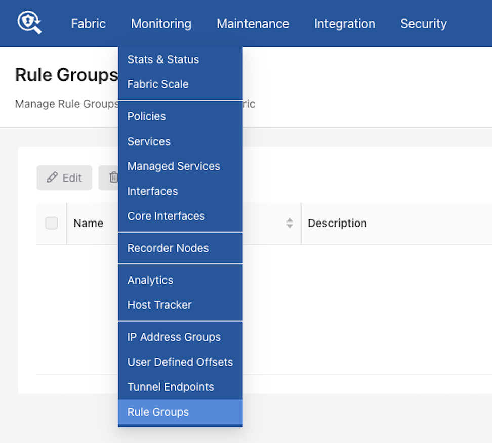
Access Rule Groups through the main navigation menu under Monitoring.
The dashboard presents a tabular view of all configured rule groups.
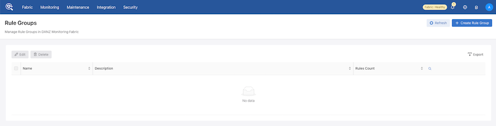
Follow the steps outlined in the following content to manage rule groups and rules (Create, Import, Edit, or Delete):
- From the Rules Group dashboard select + Create Rule Group.
Figure 19. Creating Rule Groups 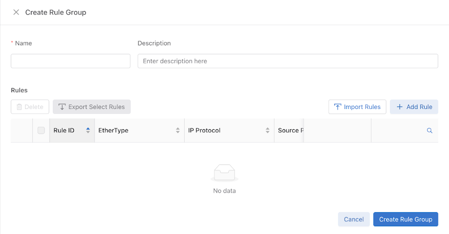 Note: The workflows within this drawer align with the Policies dashboard to ensure a consistent user experience. Use the controls Import Rules and + Add Rule to add or import individual rules.
 - To add a Single Rule, select Add Rule.
- Use Add Rule to save the entry.
Figure 20. Add Single Rule 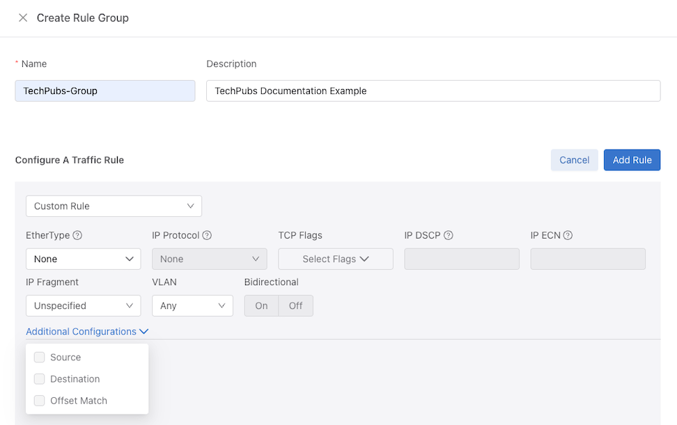
- Select Create Rule Group to save the rule group.
Figure 21. Save Rule Group 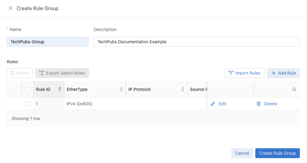
- The newly created rule group appears in the Rule Groups dashboard.
Figure 22. Updated Rule Group Dashboard 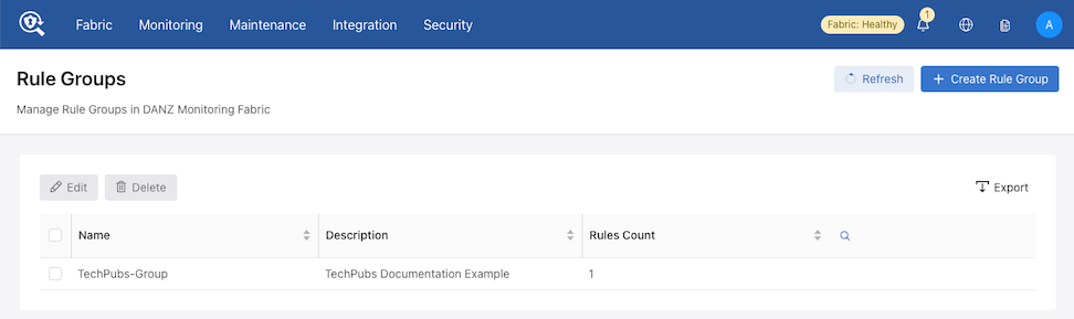
- Use Add Rule to save the entry.
- The Import Rules function uploads rule configurations from a text file.
- Choose an existing rule group from the Rule Groups dashboard or select + Create Rule Group followed by Import Rules to open the configuration dialog.
Figure 23. Create Rule Group - Import Rules  The Import Rule window appears.
Figure 24. Import Rule 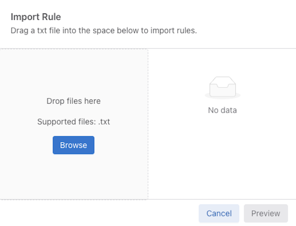
- Select Preview to verify the parsed rules.
Figure 25. Preview Imported Rule 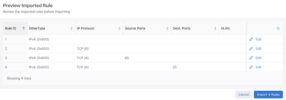
- Optional Step: Select Edit next to an entry in the Preview Imported Rule table to modify specific rule parameters.
Figure 26. Edit Imported Rule 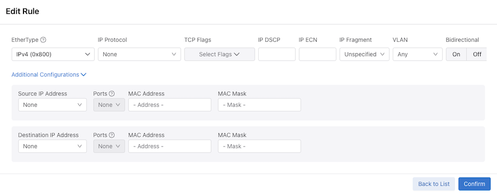
- Select Create Rule Group to save the rule group.
Figure 27. Create Imported Rule Group 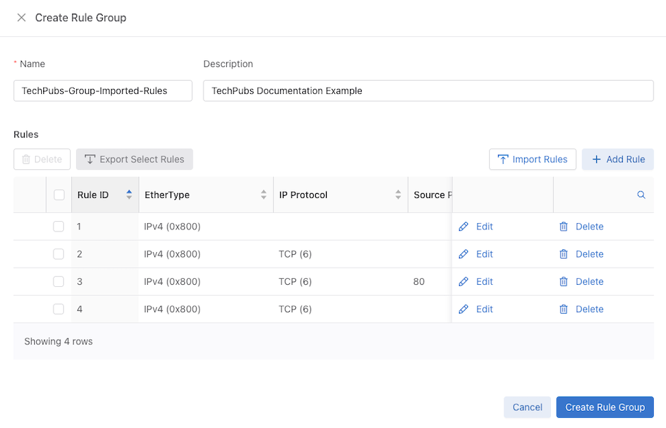
- Choose an existing rule group from the Rule Groups dashboard or select + Create Rule Group followed by Import Rules to open the configuration dialog.
- Editing a Rule Group.
- Use the Edit button.
Figure 28. Edit Rule Group 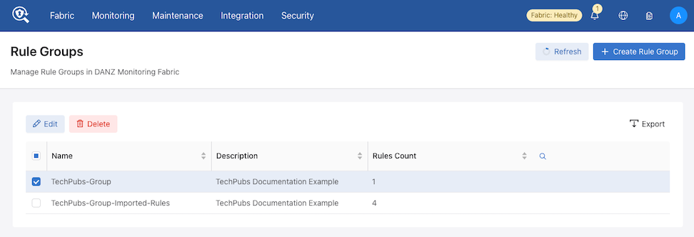
- The system opens the editing panel (identical to the creation interface).
Figure 29. Edit Rule Group 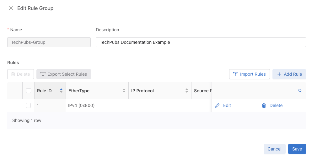
- Use the Edit button.
- Deleting a Rule Group
- Select one or more rows in the table.
Figure 30. Delete Rule Groups 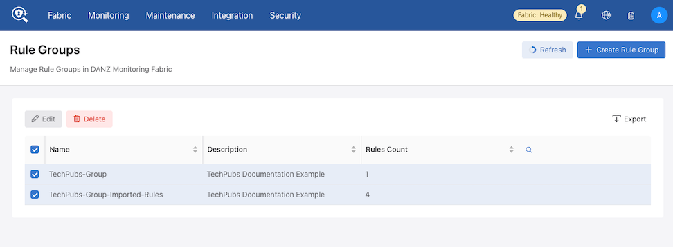
- Use the Delete button.
- The system displays a confirmation dialog.
Figure 31. Confirm Delete 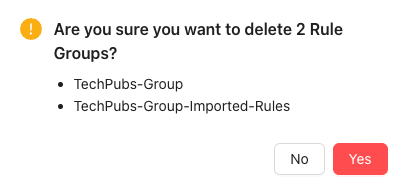
- Select Yes to permanently delete the selected rule groups.
- Select one or more rows in the table.
Using the CLI to Configure Interface Groups
TAP-PORT-GRP, and a delivery interface group, TOOL-PORT-GRP.
controller-1(config-switch)# filter-interface-group TAP-PORT-GRP
controller-1(config-filter-interface-group)# filter-interface TAP-PORT-1
controller-1(config-filter-interface-group)# filter-interface TAP-PORT-2
controller-1(config-switch)# delivery-interface-group TOOL-PORT-GRP
controller-1(config-delivery-interface-group)# delivery-interface TOOL-PORT-1
controller-1(config-delivery-interface-group)# delivery-interface TOOL-PORT-2
- Filter Interface Groups
controller-1(config-filter-interface-group)# show filter-interface-group
! show filter-interface-group TAP-PORT-GRP
# Name Big Tap IF Name                    Switch            IF Name    Direction Speed   State VLAN Tag
-|------------|--------------------------|-----------------|----------|---------|-------|-----|--------|
1 TAP-PORT-GRP TAP-PORT-1                 DMF-CORE-SWITCH-1 ethernet17 rx        100Gbps up           0
2 TAP-PORT-GRP TAP-PORT-2                 DMF-CORE-SWITCH-1 ethernet18 rx        100Gbps up           0
controller1(config-filter-interface-group)#
- Delivery Interface Groups
controller1(config-filter-interface-group)# show delivery-interface-group
! show delivery-interface-group DELIVERY-PORT-GRP
# Name Big Tap      IF Name         Switch                IF Name    Direction Speed  Ratelimit State Strip Forwarding Vlan
-|-----------------|---------------|---------------------|----------|---------|------|---------|-----|---------------------|
1 TOOL-PORT-GRP     TOOL-PORT-1     DMF-DELIVERY-SWITCH-1 ethernet15 tx        10Gbps           up    True
2 TOOL-PORT-GRP     TOOL-PORT-2     DMF-DELIVERY-SWITCH-1 ethernet16 tx        10Gbps           up    True
controller-1(config-filter-interface-group)#
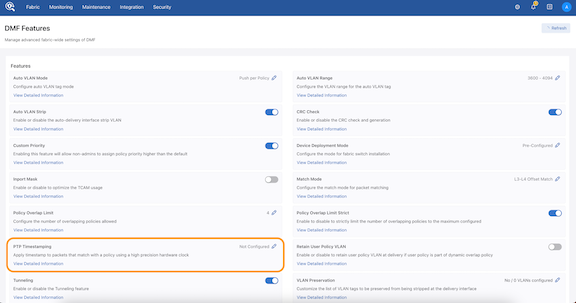
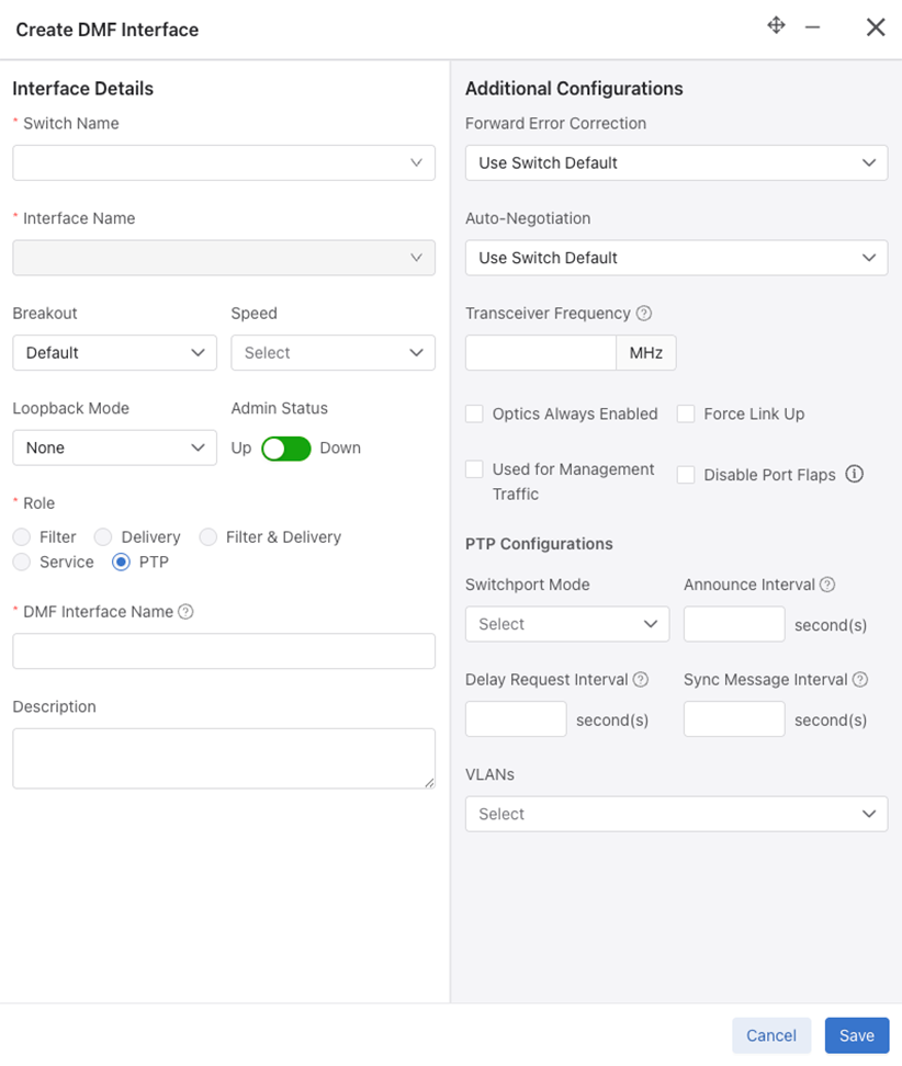
PTP Timestamping
DANZ Monitoring Fabric (DMF) rewrites the source MAC address of packets that match a policy with a 48-bit timestamp value sourced from a high-precision hardware clock.
- Connect a switch with a filter interface to a PTP network with a dedicated interface for the Precision Time Protocol. With a valid PTP interface, the switch will be configured in boundary clock mode and can sync the hardware clock with an available Grandmaster clock.
- Once configuring a policy to use timestamping, any packet matching on this policy will get its source MAC address rewritten with a timestamp value. The same holds true for any overlapping policy that carries traffic belonging to a user policy with timestamp enabled.
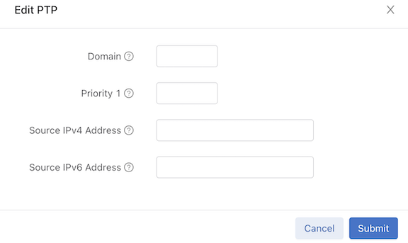
- The following options are available to configure a switch in boundary mode:
- domain: Value for data plane PTP domain (0-255) (optional)
- Priority1: Value of priority1 data plane PTP (0-255) (optional)
- Source IPv4 Address: Used to restamp PTP messages from a switch to the endpoints (optional)
- Source IPv6 Address: Used to restamp PTP messages from a switch to the endpoints (optional)
- The following options are available to configure an interface with role “ptp”:
- Announce Interval: Set ptp announce interval between messages (-3,4). Default is 1 (optional)
- Delay Request Interval: Set ptp delay request interval between messages (-7,8). The default is 5 (optional)
- Sync Message Interval: Set ptp sync message interval between messages (-7,3). The default is 0 (optional)
- PTP Vlan: VLANs used for Trunk or Access mode of operation for a ptp interface
- A policy should have enabled timestamping and have its filter interfaces on a switch with a valid PTP config to get its packets timestamped.
Platform Compatibility
DANZ Monitoring Fabric (DMF) supports the timestamping feature on 7280R3 switches.
show switch all property command to check which switch in DMF fabric supports timestamping. If the following properties exist in the output, the feature is supported:
- ptp-timestamp-cap-replace-smac
- ptp-timestamp-cap-header-48bit
- ptp-timestamp-cap-flow-based
# show switch all property
# Switch                        ...   PTP Timestamp Supported Capabilities
-|----------------------------| ...  |-------------------------------------|
1 S1 (00:00:2c:dd:e9:96:2b:ff)  ...   ptp-timestamp-cap-replace-smac,
                                ...   ptp-timestamp-cap-header-64bit,
                                ...   ptp-timestamp-cap-header-48bit,
                                ...   ptp-timestamp-cap-flow-based,
                                ...   ptp-timestamp-cap-add-header-after-l2
2 S2 (00:00:cc:1a:a3:91:a7:6c)  ...
2 S3 (00:00:cc:1a:a3:c0:94:3e)  ...
Configuration
The following three sections describe the configuration for PTP and timestamping:
Configuring PTP Timestamping using the CLI
Configure the switch at a global level under the config submode in the CLI or for each switch under the config-switch submode. Irrespective of the place, it has the following options:
-
Domain: Set the data plane PTP domain. The default value is 0. Valid values are [0 to 255] inclusive. -
Priority1: Set the value of priority1 data plane PTP. The default value is 128. Valid values are [0 to 255] inclusive. -
Source-ipv4-address: This is the source IPv4 address used to restamp PTP messages from this switch to the endpoints. Some master clock devices do not accept default source IP (0.0.0.0). If so, configureit can to sync with such devices. The default is 0.0.0.0 . -
Source-ipv6-address: This is the source IPv6 address used to restamp PTP messages from this switch to the endpoints. Some master clock devices do not accept default source IP (::/0). If so, configure it to sync with such devices. The default is ::/0 .
All fields are optional, and default values are selected if not configured by the user.
Global Configuration
The global configuration is a central place to provide a common switch config for PTP. It only takes effect after creating a ptp-interface for a switch. Under the config submode, provide PTP switch properties using the following commands:
> enable
# config
(config)# ptp priority1 0 domain 1 source-ipv4-address 1.1.1.1
Local Configuration
The local configuration provides a local PTP configuration or overrides a global PTP config for a selected switch. Select the switch using the command switch switch name. PTP switch config (local or global) only takes effect after creating a ptp-interface for a switch. Under the config-switch submode, provide local PTP switch properties using the following commands:
(config)# switch eos
(config-switch)# ptp priority1 1 domain 2
Configuring PTP Timestamping using the GUI
Global Configuration
Local Configuration
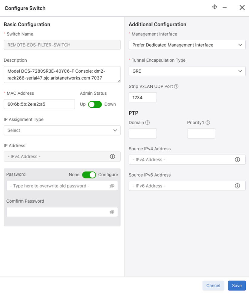
Provide a local PTP configuration for the switch or override the global PTP configuration for a selected switch while configuring or editing a switch configuration (under the PTP step) using . Select a switch in the Configuration dashboard.
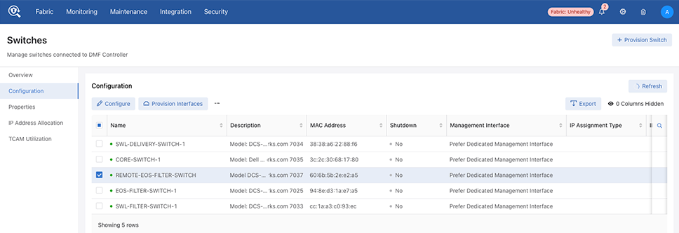
Select Configure.
PTP Interface Configuration
Configure a PTP Interface on the dashboard.

Select Create PTP Interface.
Timestamping Policy Configuration
PTP Interface Configuration
A switch that syncs its hardware clock using PTP requires a physical front panel interface configured as a PTP interface. This interface is solely responsible for communication with the master clock and has no other purpose.
To configure the PTP interface, select an interface on the switch, as illustrated in the following command.
(config-switch)# interface Ethernet6/1
Use the role command to assign a ptp role and interface name and select switchport-mode for the specified interface.
(config-switch-if)# role ptp interface-name ptp1 access-mode announce-interval 1 delay-request-interval 1 sync-message-interval 1
- trunk-mode
- access-mode
- routed-mode
The switchport mode configuration for a PTP interface is necessary to match the PTP master switch's interface configuration. Configure the master switch to communicate PTP messages with or without a vlan tag. Use the trunk-mode with the appropriate ptp vlan when configuring the neighbor similarly. If the neighbor's interface is in switch-port access mode or routed mode, use either of these to match it on the filter switch.
Other fields are optional, using default values when no configuration is provided.
- announce-interval: Set PTP to announce interval between messages [-3,4]. The default value is 1.
- delay-request-interval: Set PTP delay request interval between messages [-7,8]. The default value is 5.
- sync-message-interval: Set PTP sync message interval between messages (-7,3). The default value is 0.
(config-switch-if)# ptp vlan 1
(config-switch-if)# ptp vlan 2
In routed switchport mode, we ignore the configured VLANs. In access switchport mode, the first VLAN is used for programming while ignoring the rest. In trunk switchport mode, all configured VLANs are programmed into the switch.
Policy Configuration for Timestamping
DANZ Monitoring Fabric (DMF) supports flow-based timestamping. This function requires programming a policy to match relevant traffic and enable timestamping for the matched traffic.
Create a policy using the command policy policy name.
Under config-policy submode, enable timestamping using the following command:
(config-policy)# use-timestamping
L2GRE Encapsulation of Packets with Arista Timestamp Headers
L2GRE encapsulation of packets with Arista timestamp headers is an extension of an existing feature allowing DANZ Monitoring Fabric (DMF) to use intra-fabric L2GRE tunnels.
These tunnels enable forwarding unmodified production network packets over intermediate L3 networks used by DMF, which can now forward packets with Arista Networks Timestamp headers across L2GRE tunnels defined on EOS switches.
When a PTP header-based timestamping capable filter switch is in a remote location, and the remote filter switches connect to the centralized tool farm via L2GRE tunnels, timestamp the packets using PTP timestamping. These packets are encapsulated in an L2GRE header and sent to the core switch via the L2GRE tunnel. The timestamped packets will properly decapsulate at the remote end and be forwarded to the destination tools.
Please refer to the Tunneling Between Data Centers section on using L2GRE tunnels in DMF.
Using the CLI Show Commands
PTP State Show Commands
Use the show switch switch name ptp info| masters | interface | local-clock command to obtain the PTP state of the selected switch.
The show switch switch name ptp info command summarizes the switch's PTP state and the PTP interfaces' status.
Controller# show switch eos ptp info
PTP Mode: Boundary Clock
PTP Profile: Default ( IEEE1588 )
Clock Identity: 0x2c:dd:e9:ff:ff:96:2b:ff
Grandmaster Clock Identity: 0x44:a8:42:ff:fe:34:fd:7e
Number of slave ports: 1
Number of master ports: 1
Slave port: Ethernet1
Offset From Master (nanoseconds): -128
Mean Path Delay (nanoseconds): 71
Steps Removed: 2
Skew (estimated local-to-master clock frequency ratio): 1.0000080070748882
Last Sync Time: 00:52:44 UTC Aug 09 2023
Current PTP System Time: 00:52:44 UTC Aug 09 2023
Interface       State        Transport    Delay
Mechanism
--------------- ------------ --------------- ---------
Et1 Slave        ipv4         e2e
Et47Master       ipv4         e2e
The show switch switch name ptp master command provides information about the PTP master and grandmaster clocks.
Controller# show switch eos ptp master
Parent Clock:
Parent Clock Identity: 0x28:99:3a:ff:ff:21:81:d3
Parent Port Number: 10
Parent IP Address: N/A
Parent Two Step Flag: True
Observed Parent Offset (log variance): N/A
Observed Parent Clock Phase Change Rate: N/A

Grandmaster Clock:
Grandmaster Clock Identity: 0x44:a8:42:ff:fe:34:fd:7e
Grandmaster Clock Quality:
Class: 127
Accuracy: 0xfe
OffsetScaledLogVariance: 0x7060
Priority1: 120
Priority2: 128
The show switch switch name ptp interface
interface name command provides the PTP interface configuration and state on the device.
Controller# show switch eos ptp interface Ethernet1
Ethernet1
Interface Ethernet1
PTP: Enabled
Port state: Slave
Sync interval: 1.0 seconds
Announce interval: 2.0 seconds
Announce interval timeout multiplier: 3
Delay mechanism: end to end
Delay request message interval: 2.0 seconds
Transport mode: ipv4
Announce messages sent: 3
Announce messages received: 371
Sync messages sent: 4
Sync messages received: 739
Follow up messages sent: 3
Follow up messages received: 739
Delay request messages sent: 371
Delay request messages received: 0
Delay response messages sent: 0
Delay response messages received: 371
Peer delay request messages sent: 0
Peer delay request messages received: 0
Peer delay response messages sent: 0
Peer delay response messages received: 0
Peer delay response follow up messages sent: 0
Peer delay response follow up messages received: 0
Management messages sent: 0
Management messages received: 0
Signaling messages sent: 0
Signaling messages received: 0
The show switch switch name ptp local-clock command provides PTP local clock information.
Controller# show switch eos ptp local-clock
PTP Mode: Boundary Clock
Clock Identity: 0x2c:dd:e9:ff:ff:96:2b:ff
Clock Domain: 0
Number of PTP ports: 56
Priority1: 128
Priority2: 128
Clock Quality:
Class: 248
Accuracy: 0x30
OffsetScaledLogVariance: 0xffff
Offset From Master (nanoseconds): -146
Mean Path Delay: 83 nanoseconds
Steps Removed: 2
Skew: 1.0000081185368557
Last Sync Time: 01:01:41 UTC Aug 09 2023
Current PTP System Time: 01:01:41 UTC Aug 09 2023
Policy State Show Commands
Use the show policy command to view the timestamping status for a given policy.
> show policy
# Policy Name Action             Runtime Status Type       Priority Overlap Priority Push VLAN Filter BW Delivery BW Post Match Filter Traffic Delivery Traffic Services Installed Time Installed Duration Ptp Timestamping
-|-----------|------------------|--------------|----------|--------|----------------|---------|---------|-----------|-------------------------|----------------|--------|--------------|------------------|----------------|
1 p1          unspecified action inactive       Configured 100      0                1         -         -           -                         -                                                           True
Configuration Validation Messages
In push-per-policy mode, a validation exception occurs if a policy uses NetFlow managed-service with records-per-interface option and the same policy also uses timestamping. The following message appears:
Validation failed: Policy policy1 cannot have timestamping enabled along with header modifying netflow service.
Netflow service netflow1 is configured with records-per-interface in push-per-policy mode
In push-per-policy mode, a validation exception occurs if a policy uses the ipfix managed-service (using a template with records-per-dmf-interface key) and the same policy also uses timestamping. The following message appears:
Validation failed: Policy policy1 cannot have timestamping enabled along with header modifying ipfix service.
Ipfix service ipfix1 is configured with records-per-dmf-interface in push-per-policy mode
Only unicast source-ipv4-address or source-ipv6-address are allowed in the switch PTP config.
Examples of invalid ipv6 addresses: ff02::1, ff02::1a, ff02::d, ff02::5
Validation failed: Source IPv6 address must be a unicast address
Examples of invalid ipv4 addresses: 239.10.10.10, 239.255.255.255, 255.255.255.255
Validation failed: Source IPv4 address must be a unicast address
Troubleshooting
A policy programmed to use timestamping can fail for the following reasons:
-
The filter switch does not support syncing its hardware clock using PTP.
-
An unconfigured PTP interface or the interface is inactive.
-
The PTP switch configuration or PTP interface configuration is invalid or incomplete.
-
Configuring the PTP interface on a logical port (Lag or Tunnel).
Reasons for failure will be available in the runtime state of the policy and viewed using the show policy policy name command.
As the Platform Compatibility Section describes, use the show switch all
properties command to confirm a switch supports the feature.
Limitations
The source MAC address of the user packet is re-written with a 48-bit timestamp value on the filter switch.
This action can exhibit the following behavior changes or limitations:
- Dedup managed service will not work as expected. A high-precision timestamp can be different for duplicate packet matching on two different filter interfaces. Thus, the dedup managed service will consider this duplicate packet to be different in the L2 header. To circumvent this limitation, use an anchor/offset in the dedup managed-service config to ignore the source MAC address.
- Any Decap managed service except for
decap-l3-mplswill remove the timestamp information header. - The user source MAC address is lost and unrecoverable when using this feature.
- The
rewrite-dst-macfeature cannot be used on the filter interface that is part of the policy using the timestamping feature. - In push-per-filter mode, if a user has src-mac match condition as part of their policy config, the traffic will not be forwarded as expected and can get dropped at the core switch.
- The
in-port maskingfeature will be disabled for a policy using PTP timestamping. - Logical ports (Lag/Tunnel) as PTP interfaces are not allowed.