Tunneling Between Data Centers
This chapter describes establishing Generic Routing Encapsulation (GRE) and or Virtual Extensible LAN (VXLAN) tunnels between DMF switches in different locations or between a DMF switch and a third-party device.
Understanding Tunneling
- Connect switch ports in the main data center and the remote location to the appropriate WAN routers and ping each interface to ensure IP connectivity is established.
- Create tunnel endpoints and configure the tunnel attributes on each end of the tunnel.
- The CRC Check option must be enabled if tunneling is enabled, which it is by default. If CRC checking is disabled, re-enable it before configuring a tunnel.
- In the case of GRE tunnels, the optional gre-key-decap value on the receiving end must match the GRE key value of the sender. The option exists to set multiple values on the same tunnel to decapsulate traffic with different keys.
- A single switch can initiate multiple tunnels. Configure a separate encap-loopback-interface for each tunnel (transmit-only or bidirectional).
- Set the loopback-mode to mac on the encap-loopback-interface.
- L2GRE tunnels are not supported on DMF 7280R and 7280R2 switches.
- DSCP configuration is not supported.
- Traffic steering for traffic arriving on an L2GRE tunnel will only allow for matching based on inner src/dst IP, IP protocol, and inner L4 src/dst port.
- Packets may only be redirected to a single L2GRE tunnel.
- Packets may not be load-balanced across multiple L2GRE tunnels.
- Only IPv4 underlays in the default VRF are supported.
- Matching on inner IPv6 headers may not be supported.
- The maximum number of tunnels on EOS Jericho switches is 32.
- There is no bi-directional tunnel support. The parent/uplink router-facing interface is used for either encapsulation or decapsulation, but not simultaneously.
- When using tunnel-as-a-filter, there is no inner L3/L4 matching support immediately after decapsulation in the same switch pass. Using a loopback may work around this limitation.
- VXLAN tunnels are currently NOT supported on 7280 switches.
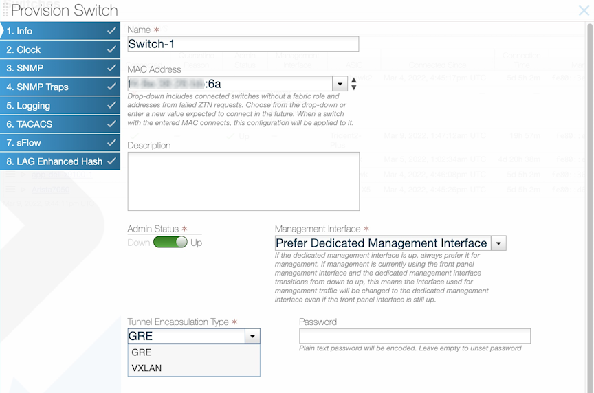
Encapsulation Type
DANZ Monitoring Fabric (DMF) supports VXLAN tunnel type and Level-2 Generic Routing Encapsulation (L2GRE). The tunnel type is a per-switch configuration, setting the switch pipeline to VXLAN or L2GRE. Once the switch pipeline is set, all tunnels configured on the switch will use the same tunnel type.
The encapsulation type can be configured in the GUI while adding a new switch into the DMF Controller, as shown in the figure below:
Using Tunnels in Policies
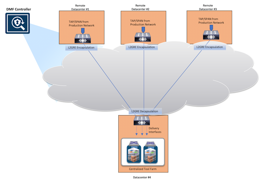
Tunnels can be used as a core link, filter interface, or delivery interface. The most common use case is linking multiple sites, using the tunnel as a core link. If used as a core link, DMF automatically discovers the link as if it were a physical link and similarly determines connectivity (link-state). If the tunnel goes down for any reason, DMF treats the failure as it would a physical link failure.
Another typical use case for the tunnel is as a filter interface to decapsulate L2 GRE/VXLAN tunneled production traffic or a tunnel initiated by another DMF instance managed by a different DMF Controller. Use the tunnel endpoint as a delivery interface to encapsulate filtered monitoring traffic to send to analysis tools or another DANZ Monitoring Fabric managed by a different DMF Controller.
Configure a GRE Tunnel
To configure a VXLAN tunnel, perform the following steps:
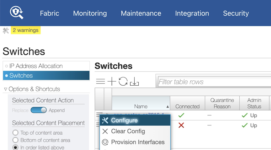
- On the Switches page, select the Menu control next to the switch or interface to include in the tunnel and select Create Tunnel.
Alternatively, configure tunnels from the page by selecting the option. The system displays the dialog as shown in the figure below:
Figure 4. Configure VXLAN Tunnel 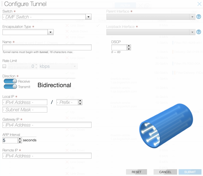
Configure a VXLAN Tunnel
To configure a VXLAN tunnel using the GUI, perform the following steps:
- On the Switches page, select the Menu control next to the switch or interface to include in the tunnel and select Create Tunnel.
Alternatively, configure tunnels from the page by selecting the option. The system displays the dialog as shown in the figure below:
Figure 5. Configure VXLAN Tunnel
Push Per Policy or Push
Per Filter Interface.Viewing or Modifying Existing Tunnels
The expanded row displays the status and other properties of the tunnel configured for the selected interface. Use the Menu control and select Configure Tunnel to modify the tunnel configuration. Select Delete Tunnel to remove the tunnel.
Using a Tunnel with User-defined Offsets
With an L2-GRE or VXLAN tunnel, matching traffic on a user-defined offset results in dropping interesting traffic. The tunnel header throws off the offset calculation, and the selected traffic may be dropped. This behavior is due to how switch hardware calculates the anchor and offset concerning incoming packets. When the core link is a tunnel, the anchor and offset calculation differs when encapsulating packets compared to when decapsulating.
- Avoid matching on user-defined offsets on tunnel interfaces
- Avoid using a tunnel as a core link when matching on a user-defined offset
Avoid matching on user-defined offsets when the ingress filter interface is a tunnel by filtering on the user-defined offset before the traffic enters a tunnel used as a filter interface. This preserves the LLDP messaging on the core tunnel link, but it requires an extra physical loopback interface on the encapsulating switch. The figure below illustrates both of these workarounds. In either case, a UDF match is applied to the ingress traffic on filter interface F. For example, the policy might apply a match at offset 20 after the start of the L4 header. In both workarounds, the policy has been split into two policies:
P1: F to D1, match on user-defined offset P2: F1 to D, match any.
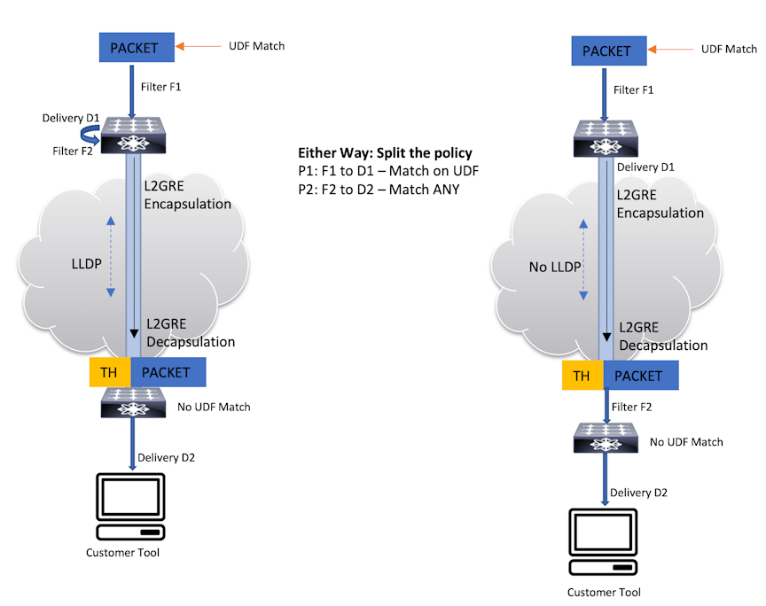
In the example on the right, the tunnel endpoints are configured as filter and delivery interfaces. This solution avoids using the tunnel as a core link and does not require an extra physical loopback interface. However, LLDP updates are lost on the tunnel link.
Configuring Wildcard Tunnels
Wildcard Tunnels on SAND Platforms
The Wildcard tunneling feature allows the DANZ Monitoring Fabric (DMF) to decapsulate L2GRE-based tunneled traffic from any remote source. This feature, supported on Switch Light OS (SWL) based DMF switches in prior releases, now allows wildcard tunnels on Arista EOS-based DMF switches.
Platform Compatibility
EOS switches with Jericho2 or higher ASICs compatible with DMF 8.5.0 that support L2GRE tunneling. L2GRE tunneling on EOS SAND platforms is only supported on Arista 7280R3 switches.
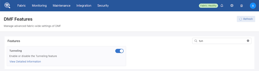
Enable Tunneling by navigating to the DMF Features page and selecting the gear icon in the navigation bar.

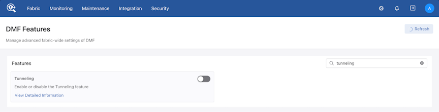
Select the toggle switch to enable the Tunneling feature on DMF.
Steps to Enable Wildcard Tunnels
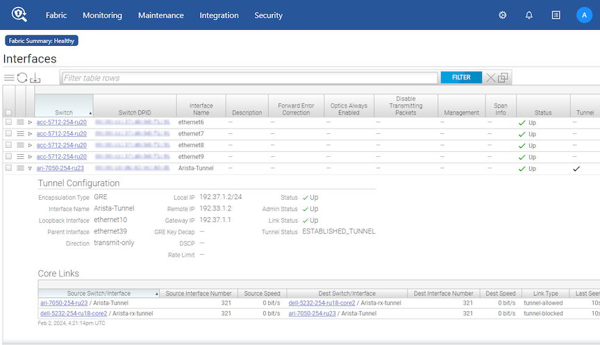
- Locate the Switches tab on the page.
Figure 11. Fabric > Interfaces 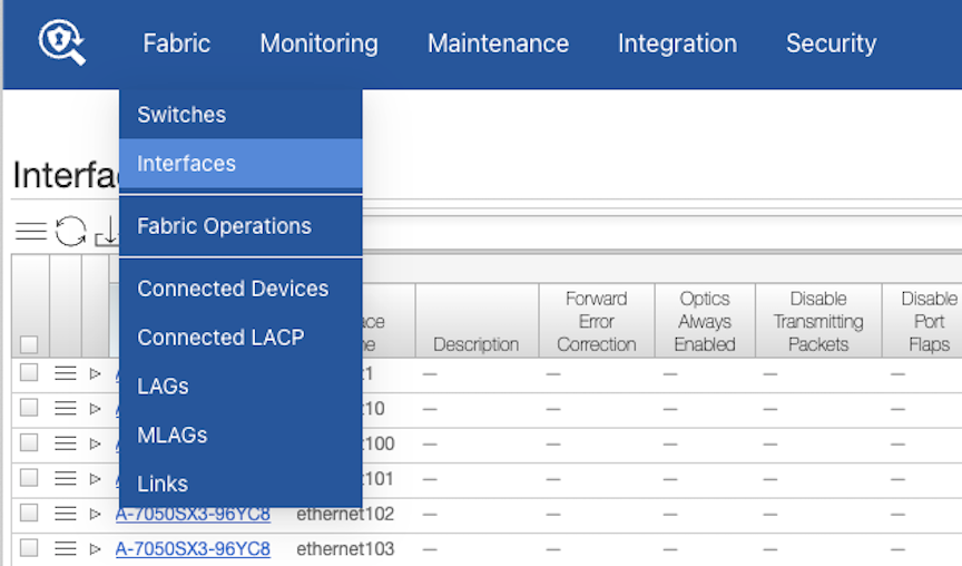
- Select the Create Tunnel option from the table menu.
Figure 12. Create Tunnel 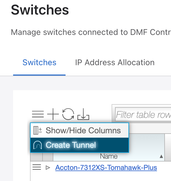
- Create a Tunnel (select Encapsulation Type as GRE) by entering the required fields. To enable wildcard support, enter the Remote IP input with data as shown below.
Figure 13. Configure Tunnel 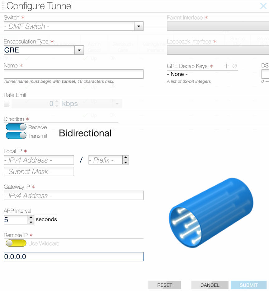
Using the Command Line Interface
Configure a GRE Tunnel
To configure a GRE tunnel using the CLI, perform the following steps:
!
switch remote-dc1-filter-sw
gre-tunnel-interface tunnel1
remote-ip 192.168.200.50
gre-key-decap 4097 === 4097 is the VPN key used for the tunnel ID
parent-interface ethernet6
local-ip 192.168.100.50 mask 255.255.255.0 gateway-ip 192.168.100.1
direction bidirectional encap-loopback-interface ethernet38
!
switch main-dc-delivery-sw
gre-tunnel-interface tunnel1
remote-ip 192.168.100.50
gre-key-decap 4097 === 4097 is the VPN key used for the tunnel ID
parent-interface ethernet5
local-ip 192.168.200.50 mask 255.255.255.0 gateway-ip 192.168.200.1
direction bidirectional encap-loopback-interface ethernet3
!
switch remote-dc1-filter-sw
gre-tunnel-interface tunnel1
remote-ip 192.168.200.50
gre-key-decap 4097 === 4097 is the VPN key used for the tunnel ID
interface parent-interface ethernet6
local-ip 192.168.100.50 mask 255.255.255.0 gateway-ip 192.168.100.1
direction transmit-only encap-loopback-interface ethernet38
!
switch main-dc-delivery-sw
gre-tunnel-interface tunnel1
remote-ip 192.168.100.50
gre-key-decap 4097 === 4097 is the VPN key used for the tunnel ID
parent-interface ethernet5
local-ip 192.168.200.50 mask 255.255.255.0 gateway-ip 192.168.200.1
direction receive-only
Rate Limit the Packets on a GRE Tunnel
switch DMF-CORE-SWITCH-1
gre-tunnel-interface tunnel1
direction bidirectional encap-loopback-interface ethernet10
------------------------------example truncated------------
interface ethernet10
rate-limit 1000
View GRE Tunnel Interfaces
All CLI show commands for regular interfaces apply to GRE tunnel interfaces.
Use the show running-config command to view the configuration of tunnel interfaces.
controller-1# show tunnel
# Switch DPID               Tunnel Name Tunnel Status     Direction     Src IP       Dst IP       Parent Name  Loopback Name
-|-------------------------|-----------|------------------|-------------|------------|------------|------------|-------------|
1 DMF-CORE-SWITCH-1         tunnel1     ESTABLISHED_TUNNEL bidirectional 198.82.215.1 216.47.143.1 ethernet5:1 ethernet6
2 DMF-CORE-SWITCH-2         tunnel1     ESTABLISHED_TUNNEL bidirectional 216.47.143.1 198.82.215.1 ethernet11:3 ethernet5
3 DMF-CORE-SWITCH-2         tunnel2     ESTABLISHED_TUNNEL bidirectional 192.168.43.1 192.168.42.1 ethernet11:4 ethernet17
4 DMF-CORE-SWITCH-3         tunnel2     ESTABLISHED_TUNNEL bidirectional 192.168.42.1 192.168.43.1 ethernet6 ethernet33

controller-1# show tunnel switch DMF-CORE-SWITCH-2
# Switch DPID               Tunnel Name Tunnel Status     Direction     Src IP       Dst IP       Parent Name  Loopback Name
-|-------------------------|-----------|------------------|-------------|------------|------------|------------|-------------|
1 DMF-CORE-SWITCH-2         tunnel1     ESTABLISHED_TUNNEL bidirectional 216.47.143.1 198.82.215.1 ethernet11:3 ethernet5
2 DMF-CORE-SWITCH-2         tunnel2     ESTABLISHED_TUNNEL bidirectional 192.168.43.1 192.168.42.1 ethernet11:4 ethernet17

controller-1# show tunnel switch DMF-CORE-SWITCH-2 tunnel1
# Switch DPID               Tunnel Name Tunnel Status     Direction     Src IP       Dst IP       Parent Name  Loopback Name
-|-------------------------|-----------|------------------|-------------|------------|------------|------------|-------------|
1 DMF-CORE-SWITCH-2         tunnel1     ESTABLISHED_TUNNEL bidirectional 216.47.143.1 198.82.215.1 ethernet11:3 ethernet5
controller-1#
Configure a VXLAN Tunnel
To configure a VXLAN tunnel using the CLI, perform the following steps:
!
switch remote-dc1-filter-sw
vxlan-tunnel-interface tunnel1
remote-ip 192.168.200.50
parent-interface ethernet6
local-ip 192.168.100.50 mask 255.255.255.0 gateway-ip 192.168.100.1
direction bidirectional encap-loopback-interface ethernet38
!
switch main-dc-delivery-sw
vxlan-tunnel-interface tunnel1
remote-ip 192.168.100.50
parent-interface ethernet5
local-ip 192.168.200.50 mask 255.255.255.0 gateway-ip 192.168.200.1
direction bidirectional encap-loopback-interface ethernet3
!
switch remote-dc1-filter-sw
vxlan-tunnel-interface tunnel1
remote-ip 192.168.200.50
interface parent-interface ethernet6
local-ip 192.168.100.50 mask 255.255.255.0 gateway-ip 192.168.100.1
direction transmit-only encap-loopback-interface ethernet38
!
switch main-dc-delivery-sw
vxlan-tunnel-interface tunnel1
remote-ip 192.168.100.50
parent-interface ethernet5
local-ip 192.168.200.50 mask 255.255.255.0 gateway-ip 192.168.200.1
direction receive-only
Rate Limit the Packets on a VXLAN Tunnel
switch DMF-CORE-SWITCH-1
vxlan-tunnel-interface tunnel1
direction bidirectional encap-loopback-interface ethernet10
<snip>
interface ethernet10
rate-limit 1000
View VXLAN Tunnel Interfaces
All CLI show commands for regular interfaces apply to tunnel interfaces.
Use the show running-config command to display the configuration of tunnel interfaces.
controller-1# show tunnel
# Switch DPID Tunnel Name Tunnel Status Direction Src IP Dst IP Parent Name Loopback
Name
-|-------------------------|-----------|-----------------|-------------|------------|------------|------------|-------------|
1 DMF-CORE-SWITCH-1 tunnel1 ESTABLISHED_TUNNEL bidirectional 198.82.215.1 216.47.143.1 ethernet5:1 ethernet6
2 DMF-CORE-SWITCH-2 tunnel1 ESTABLISHED_TUNNEL bidirectional 216.47.143.1 198.82.215.1 ethernet11:3 ethernet5
3 DMF-CORE-SWITCH-2 tunnel2 ESTABLISHED_TUNNEL bidirectional 192.168.43.1 192.168.42.1 ethernet11:4 ethernet17
4 dMF-CORE-SWITCH-3 tunnel2 ESTABLISHED_TUNNEL bidirectional 192.168.42.1 192.168.43.1 ethernet6 ethernet33
controller-1#
controller-1# show tunnel switch DMF-CORE-SWITCH-2
# Switch DPID Tunnel Name Tunnel Status Direction Src IP Dst IP Parent Name Loopback Name
-|-----------------------|-----------|------------------|-------------|------------|------------|------------|-------------|
1 DMF-CORE-SWITCH-2 tunnel1 ESTABLISHED_TUNNEL bidirectional 216.47.143.1 198.82.215.1 ethernet11:3 ethernet5
2 DMF-CORE-SWITCH-2 tunnel2 ESTABLISHED_TUNNEL bidirectional 192.168.43.1 192.168.42.1 ethernet11:4 ethernet17
controller-1#
controller-1# show tunnel switch DMF-CORE-SWITCH-2 tunnel1
# Switch DPID Tunnel Name Tunnel Status Direction Src IP Dst IP Parent Name Loopback Name
-|-----------------------|-----------|------------------|-------------|------------|------------|------------|-------------|
1 DMF-CORE-SWITCH-2 tunnel1 ESTABLISHED_TUNNEL bidirectional 216.47.143.1 198.82.215.1 ethernet11:3 ethernet5
controller-1#
Configuring Wildcard Tunnels
Wildcard Tunnels on SAND Platforms
The Wildcard tunneling feature allows the DANZ Monitoring Fabric (DMF) to decapsulate L2GRE-based tunneled traffic from any remote source. This feature, supported on Switch Light OS (SWL) based DMF switches in prior releases, now allows wildcard tunnels on Arista EOS-based DMF switches.
Platform Compatibility
EOS switches with Jericho2 or higher ASICs compatible with DMF 8.5.0 that support L2GRE tunneling. L2GRE tunneling on EOS SAND platforms is only supported on Arista 7280R3 switches.
Perform the following steps to configure the tunnels.
Show Commands
All CLI show commands for regular interfaces apply to GRE tunnel interfaces. Use the show
running-config command to view the configuration of tunnel interfaces.
Enter the show tunnel command to view a tunnel interface's configuration parameters and runtime state.
Example
dmf-controller-1# show tunnel
# Switch DPID       Tunnel Name Tunnel Status      Direction     Src IP       Dst IP       Parent Name  Loopback Name
-|-----------------|-----------|------------------|-------------|------------|------------|------------|-------------|
1 DMF-CORE-SWITCH-1 tunnel1     ESTABLISHED_TUNNEL bidirectional 198.82.215.1 216.47.143.1 ethernet5:1  ethernet6
2 DMF-CORE-SWITCH-2 tunnel1     ESTABLISHED_TUNNEL bidirectional 216.47.143.1 198.82.215.1 ethernet11:3 ethernet5
3 DMF-CORE-SWITCH-2 tunnel2     ESTABLISHED_TUNNEL bidirectional 192.168.43.1 192.168.42.1 ethernet11:4 ethernet17
4 DMF-CORE-SWITCH-3 tunnel2     ESTABLISHED_TUNNEL bidirectional 192.168.42.1 192.168.43.1 ethernet6    ethernet33
Encapsulation Types
DANZ Monitoring Fabric (DMF) supports VXLAN tunnel type and Level-2 Generic Routing Encapsulation (L2GRE). The tunnel type is a per-switch configuration, setting the switch pipeline to VXLAN or L2GRE. Once the switch pipeline is set, all tunnels configured on the switch will use the same tunnel type.
Ctrl-1(config)# switch Switch-1
Ctrl-1(config-switch)# tunnel-type
gre Select GRE as the tunnel type of the switch. (default selection)
vxlan Select VxLAN as the tunnel type of the switch.
Ctrl-1(config)# show switch
# Switch Name         IP Address                  State     Pipeline Mode
-|-------------------|---------------------------|---------|----------------------------------|
1 Switch-1            fe80::d6af:f7ff:fef9:e2b0%9 connected l3-l4-offset-match-push-vlan-vxlan
2 Switch-2            fe80::e6f0:4ff:fe69:6aee%9  connected l3-l4-offset-match-push-vlan
3 Switch-3            fe80::e6f0:4ff:fe78:1ffe%9  connected l3-l4-offset-match-push-vlan-vxlan
Ctrl-1(config)#
In the above CLI output, Switch-1 and Switch-3 use the VXLAN tunnel type, as seen in the Pipeline Mode column. Switch-2 is using the L2GRE tunnel type.