Advanced Fabric Settings
This chapter describes fabric-wide configuration options required in advanced use cases for deploying DMF policies.
Configuring Advanced Fabric Settings
Page Layout
All fabric-wide configuration settings required in advanced use cases for deploying DMF policies appear in the new DMF Features Page.
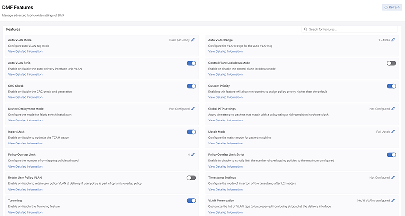
- Feature Title
- A brief description
- View / Hide detailed information link
- Current Setting
- Edit Link - Use Edit (pencil) icon to change the value.
The fabric-wide options used with DMF policies include the following:
| Feature Set | |
| Auto VLAN Mode | Auto VLAN Range |
| Auto VLAN Strip | CRC Check |
| Custom Priority | Device Deployment Mode |
| Inport Mask | Match Mode |
| Policy Overlap Limit | Policy Overlap Limit Strict |
| PTP Timestamping | Retain User Policy VLAN |
| Tunneling | VLAN Preservation |
Managing VLAN Tags in the Monitoring Fabric
- push-per-policy (default): Automatically adds a unique VLAN ID to all traffic selected by a specific policy. This setting enables tag-based forwarding.
- push-per-filter: Automatically adds a unique VLAN ID from the default auto-VLAN range (1-4094) to each filter interface. A custom VLAN range can be specified using the auto-vlan-range command. Manually assign any VLAN ID not in the auto-VLAN range to a filter interface.
The VLAN ID assigned to policies or filter interfaces remains unchanged after controller reboot or failover. However, it changes if the policy is removed and added back again. Also, when the VLAN range is changed, existing assignments are discarded, and new assignments are made.
The push-per-filter feature preserves the original VLAN tag, but the outer VLAN tag is rewritten with the assigned VLAN ID if the packet already has two VLAN tags.
| Traffic with VLAN tag type | push-per-policy Mode (Applies to all supported switches) | push-per-filter Mode (Applies to all supported switches) |
|---|---|---|
| Untagged | Pushes a single tag | Pushes a single tag |
| Single tag | Pushes an outer (second) tag | Pushes an outer (second) tag |
| Two tags | Pushes an outer (third) tag. Except on T3-based switches, it rewrites the outer tag. Due to this outer customer VLAN is replaced by DMF policy VLAN. | Rewrites the outer tag. Due to this outer customer VLAN is replaced by DMF filter VLAN. |
| Auto-VLAN Mode | Supported Platform | TCAM Optimization in the Core | L2 GRE Tunnels Support | Q-in-Q Packets Preserve Both Original Tags | Support DMF Service Node Services | Manual Tag to Filter Interface |
|---|---|---|---|---|---|---|
| Push-per-policy (default) | All | Yes | Yes | Yes | All | Policy tag overwrites manual |
| Push-per-filter | All | No | Yes | No | All | Configuration not allowed |
Tag-based forwarding, which improves traffic forwarding and reduces TCAM utilization on the monitoring fabric switches, is enabled only when choosing the push-per-policy option.
controller-1> show interface-names
~~~~~~~~~~~~~~~~~~~~~~~~ Filter Interface(s) ~~~~~~~~~~~~~~~~~~~~~~~~~~~~~~~~~~~~~~~~~~~~~~~~~~
#  DMF IF                      Switch IF     Name         Dir State Speed  VLAN Tag Analytics Ip address Connected Device
--|---------------------------|-------------|------------|---|-----|------|--------|---------|----------|----------------|
1  TAP-PORT-eth1               FILTER-SW1    ethernet1    rx  up    10Gbps 5        True
2  TAP-PORT-eth10              FILTER-SW1    ethernet10   rx  up    10Gbps 10       True
3  TAP-PORT-eth12              FILTER-SW1    ethernet12   rx  up    10Gbps 11       True
4  TAP-PORT-eth14              FILTER-SW1    ethernet14   rx  up    10Gbps 12       True
5  TAP-PORT-eth16              FILTER-SW1    ethernet16   rx  up    10Gbps 13       True
6  TAP-PORT-eth18              FILTER-SW1    ethernet18   rx  up    10Gbps 14       True
7  TAP-PORT-eth20              FILTER-SW1    ethernet20   rx  up    10Gbps 16       True
8  TAP-PORT-eth22              FILTER-SW1    ethernet22   rx  up    10Gbps 17       True
Auto VLAN Mode
Analysis tools often use VLAN tags to identify the filter interface receiving traffic. How VLAN IDs are assigned to traffic depends on which auto-VLAN mode is enabled. The system automatically assigns the VLAN ID from a configurable range of VLAN IDs from 1 to 4094 by default. Available auto-VLAN modes behave as follows:
- Push per Policy (default): Automatically adds a unique VLAN ID to all traffic selected by a specific policy. This setting enables tag-based forwarding.
- Push per Filter: Automatically adds a unique VLAN ID from the default auto-vlan-range (1-4094) to each filter interface. A new vlan range can be specified using the auto-vlan-range command. Manually assign any VLAN ID not in the auto-VLAN range to a filter interface.
The following table summarizes how VLAN tagging occurs with the different Auto VLAN modes.
| Traffic with VLAN tag type | push-per-policy Mode
(Applies to all supported switches) |
push-per-filter Mode
(Applies to all supported switches) |
|---|---|---|
| Untagged | Pushes a single tag | Pushes a single tag |
| Single tag | Pushes an outer (second) tag | Pushes an outer (second) tag |
| Two tags | Pushes an outer (third) tag. Except on T3-based switches, it rewrites the outer tag. Due to this outer customer VLAN is replaced by DMF policy VLAN. | Rewrites the outer tag. Due to this outer customer VLAN is replaced by DMF filter VLAN. |
The following table summarizes how different Auto VLAN modes affect supported applications and services.
| Auto-VLAN Mode | Supported Platform | TCAM Optimization in the Core | L2 GRE Tunnels Support | Q-in-Q Packets Preserve Both Original Tags | Supported DMF Service Node Services | Manual Tag to Filter Interface |
|---|---|---|---|---|---|---|
| Push per Policy (default) | All | Yes | Yes | Yes | All | Policy tag overwrites manual |
| Push per Filter | All | No | Yes | No | All | Configuration not allowed |
Tag-based forwarding, which improves traffic forwarding and reduces TCAM utilization on the monitoring fabric switches, is only enabled when choosing the push-per-policy option.
Use the CLI or the GUI to configure Auto VLAN Mode as described in the following topics.
Configuring Auto VLAN Mode using the CLI
To set the auto VLAN mode, perform the following steps:
Configuring Auto VLAN Mode using the GUI
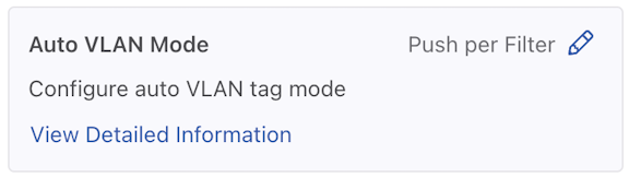
Auto VLAN Mode
- Control the configuration of this feature using the Edit icon by locating the corresponding card and the pencil icon.
Figure 4. Auto VLAN Mode Config 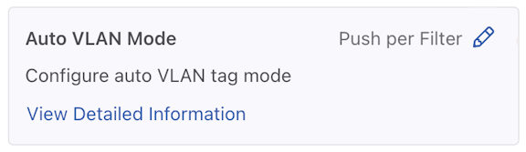
- A confirmation edit dialogue window appears, displaying the corresponding prompt message.
Figure 5. Edit VLAN Mode 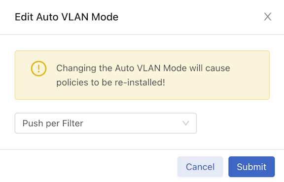
- To configure different modes, select the drop-down arrow to open the menu.
Figure 6. Drop-down Example 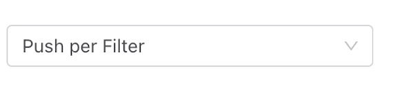
- From the drop-down menu, select the desired mode.
Figure 7. Push Per Policy 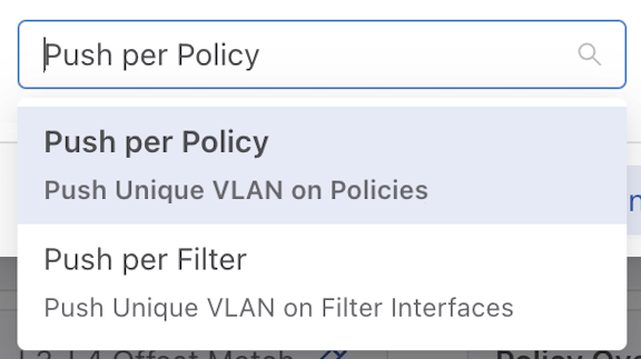
- Alternatively, enter the desired mode name in the input area.
Figure 8. Push Per Policy 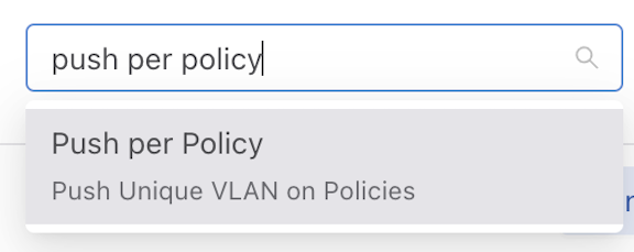
- Use Submit to confirm the configuration changes or Cancel to discard the changes.
Figure 9. Submit Button 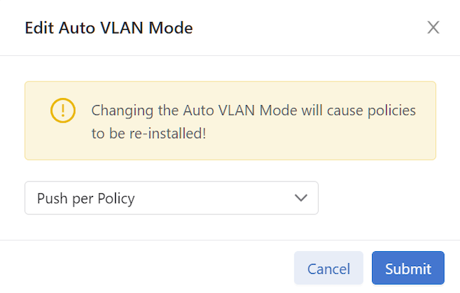
- After successfully setting the configuration, the current configuration status displays next to the edit icon.
Figure 10. Current Configuration Status 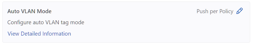
The following feature sets work in the same manner as the Auto VLAN Mode feature described above.
- Device Deployment Mode
- Match Mode
Auto VLAN Range
Auto VLAN Range
The range of automatically generated VLANs only applies when setting Auto VLAN Mode to push-per-filter. VLANs are picked from the range 1 - 4094 when not specified.
- Control the configuration of this feature using the Edit icon by locating the corresponding card and selecting the pencil icon.
Figure 11. Edit Auto VLAN Range 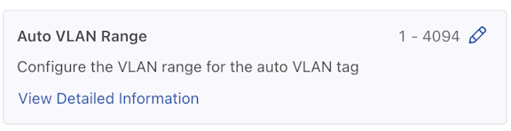
- A configuration edit dialogue window pops up, displaying the corresponding prompt message. The Auto VLAN Range defaults to 1 - 4094.
Figure 12. Edit Auto VLAN Range 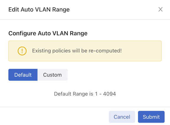
- Select Custom to configure the custom range.
Figure 13. Custom Button 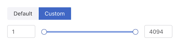
- Adjust range value (minimum value: 1, maximum value: 4094). There are three ways to adjust the value of a range:
- Directly enter the desired value in the input area, with the left side representing the minimum value of the range and the right side representing the maximum value.
- Adjust the value by dragging the slider using a mouse. The left knob represents the minimum value of the range, while the right knob represents the maximum value.
- Use the up and down arrow buttons in the input area to adjust the value accordingly. Pressing the up arrow increments the value by 1, while pressing the down arrow decrements it by 1.
- Use Submit to confirm the configuration changes or Cancel to discard the changes.
- After successfully setting the configuration, the current configuration status displays next to the edit icon.
Figure 14. Configuration Change Success 
Configuring Auto VLAN Range using the CLI
To set the Auto VLAN Range, use the following command:
auto-vlan-range vlan-min start vlan-max end
To set the Auto VLAN Range, replace start and end with the first and last VLAN ID in the desired range.
For example, the following command assigns a range of 100 VLAN IDs from 3994 to 4094:
controller-1(config)# auto-vlan-range vlan-min 3994 vlan-max 4094
Auto VLAN Strip
The strip VLAN option removes the outer VLAN tag before forwarding the packet to a delivery interface. Only the outer tag is removed if the packet has two VLAN tags. If it has no VLAN tag, the packet is not modified. Users can remove the VLAN ID on traffic forwarded to a specific delivery interface globally for all delivery interfaces. The strip VLAN option removes any VLAN ID applied by the rewrite VLAN option.
The strip vlan option removes the VLAN ID on traffic forwarded to the delivery interface. The following are the two methods available:
- Remove VLAN IDs fabric-wide for all delivery interfaces. This method removes only the VLAN tag added by DMF Fabric.
- On specific delivery interfaces. This method has four options:
- Keep all tags intact. Preserves the VLAN tag added by DMF Fabric and other tags in the traffic using strip-no-vlan option during delivery interface configuration.
- Remove only the outer VLAN tag the DANZ Monitoring Fabric added using the strip-one-vlan option during delivery interface configuration.
- Remove only the second (inner) tag. Preserves the VLAN (outer) tag added by DMF Fabric and removes the second (inner) tag in the traffic using the strip-second-vlan option during delivery interface configuration.
- Remove two tags. Removes the outer VLAN tag added by DMF fabric and inner vlan tag in the traffic using the strip-two-vlan option during delivery interface configuration.
By default, the VLAN ID is stripped when DMF adds it to enable the following options:
- Push per Policy
- Push per Filter
- Rewrite VLAN under filter-interfaces
Tagging and stripping VLANs as they ingress and egress DMF differs depending on whether the switch is a Trident 3-based.
Use the CLI or the GUI to configure Auto VLAN Strip as described in the following topics.
Auto VLAN Strip using the CLI
The strip VLAN option removes the outer VLAN tag before forwarding the packet to a delivery interface. Only the outer tag is removed if the packet has two VLAN tags. If it has no VLAN tag, the packet is not modified. Users can remove the VLAN ID on traffic forwarded to a specific delivery interface or globally for all delivery interfaces. The strip VLAN option removes any VLAN ID applied by the rewrite VLAN option.
The following are the two methods available:
- Remove VLAN IDs fabric-wide for all delivery interfaces: This method removes only the VLAN tag added by the DMF Fabric.
- Remove VLAN IDs only on specific delivery interfaces: This method has four options:
- Keep all tags intact. Preserves the VLAN tag added by DMF Fabric and other tags in the traffic using strip-no-vlan option during delivery interface configuration.
- Remove only the outer VLAN tag the DANZ Monitoring Fabric added using the strip-one-vlan option during delivery interface configuration.
- Remove only the second (inner) tag. Preserves the VLAN (outer) tag added by DMF and removes the second (inner) tag in the traffic using the strip-second-vlan option during delivery interface configuration.
- Remove two tags. Removes the outer VLAN tag added by DMF fabric and the inner VLAN tag in the traffic using the strip-two-vlan option during delivery interface configuration.
fabric-wide strip
VLAN option.- push-per-policy
- push-per-filter
- rewrite vlan under filter-interfaces
To view the current auto-delivery-interface-vlan-strip configuration, enter the following command:
controller-1> show running-config feature details
! deployment-mode
deployment-mode pre-configured
! auto-delivery-interface-vlan-strip
auto-delivery-interface-vlan-strip
! auto-vlan-mode
auto-vlan-mode push-per-policy
! auto-vlan-range
auto-vlan-range vlan-min 3200 vlan-max 4094
! crc
crc
! match-mode
match-mode full-match
! tunneling
tunneling
! allow-custom-priority
allow-custom-priority
! inport-mask
no inport-mask
! overlap-limit-strict
no overlap-limit-strict
! overlap-policy-limit
overlap-policy-limit 10
! packet-capture
packet-capture retention-days 7
To view the current auto-delivery-interface-vlan-strip state, enter the following command:
controller-1> show fabric
~~~~~~~~~~~~~~~~~~~~~ Aggregate Network State ~~~~~~~~~~~~~~~~~~~~~
Number of switches : 5
Inport masking : True
Start time : 2018-10-16 22:30:03.345000 UTC
Number of unmanaged services : 0
Filter efficiency : 3005:1
Number of switches with service interfaces : 0
Total delivery traffic (bps) : 232bps
Number of managed service instances : 0
Number of service interfaces : 0
Match mode : l3-l4-match
Number of delivery interfaces : 24
Max pre-service BW (bps) : -
Auto VLAN mode : push-per-policy
Number of switches with delivery interfaces : 5
Number of managed devices : 1
Uptime : 21 hours, 53 minutes
Total ingress traffic (bps) : 697Kbps
Max overlap policies (0=disable) : 10
Auto Delivery Interface Strip VLAN : True
controller-1(config-switch-if)# no auto-delivery-interface-vlan-strip
The delivery interface level command to strip the VLAN overrides the global auto-delivery-interface-vlan-strip command. For example, when global VLAN stripping is disabled or to override the default strip option on a delivery interface use the below options:
controller-1(config-switch-if)# role delivery interface-name TOOL-PORT-1 strip-one-vlan
controller-1(config-switch-if)# role delivery interface-name TOOL-PORT-1 strip-two-vlan
controller-1(config-switch-if)# role delivery interface-name TOOL-PORT-1 strip-second-vlan
controller-1(config-switch-if)# role delivery interface-name TOOL-PORT-1 strip-no-vlan
controller-1(config-switch-if)# role delivery interface-name name [strip-no-vlan | strip-onevlan | strip-second-vlan | strip-two-vlan]
Use the option to leave all VLAN tags intact, remove the outermost tag, remove the second (inner) tag, or remove the outermost two tags, as required.
By default, VLAN stripping is enabled and the outer VLAN added by DMF is removed.
controller-1(config-switch-if)# role delivery interface-name TOOL-PORT-1 strip-no-vlan
controller-1(config)# switch DMF-DELIVERY-SWITCH-1
controller-1(config-switch)# interface ethernet20
controller-1(config-switch-if)# role delivery interface-name TOOL-PORT-1 strip-one-vlan
controller-1(config)# auto-delivery-interface-vlan-strip
This would enable auto delivery interface strip VLAN feature.
Existing policies will be re-computed. Enter “yes” (or “y”) to continue: yes
As mentioned earlier, tagging and stripping VLANs as they ingress and egress DMF differs based on whether the switch uses a Trident 3 chipset. The following scenarios show how DMF behaves in different VLAN modes with various knobs set.
Scenario 1
- VLAN mode: Push per Policy
- Filter interface on any switch except a Trident 3 switch
- Delivery interface on any switch
- Global VLAN stripping is enabled
| VLAN tag type | No Configuration | strip-no-VLAN | strip-one-VLAN | strip-second-VLAN | strip-two-VLAN |
|---|---|---|---|---|---|
| DMF policy VLAN is stripped automatically on delivery inter- face using default global strip VLAN added by DMF | DMF policy VLAN and customer VLAN preserved | Strips the outermost VLAN that is DMF policy VLAN | DMF policy VLAN is preserved and outermost customer VLAN is removed | Strip two VLANs, DMF policy VLAN and customer outer VLAN removed | |
| Untagged | Packets exit DMF as untagged packets | Packets exit DMF as singly tagged packets. VLAN in the packet is DMF policy VLAN. | Packets exit DMF as untagged packets. | Packets exit DMF as single-tagged traffic. VLAN in the packet is DMF policy VLAN. | Packets exit DMF as untagged traffic. |
| Singly Tagged | Packets exit DMF as single-tagged traffic with customer VLAN. | Packets exit DMF as doubly tagged packets. Outer VLAN in the packet is DMF policy VLAN. | Packets exit DMF as single-tagged traffic with customer VLAN. | Packets exit DMF as single-tagged traffic. VLAN in the packet is DMF policy VLAN. | Packets exit DMF as untagged traffic. |
| Doubly Tagged | Packet exits DMF as doubly tagged traffic. Both VLANs are customer VLANs. | Packet exits DMF as triple-tagged packets. Outermost VLAN in the packet is the DMF policy VLAN. | Packet exits DMF as doubly tagged traffic. Both VLANs are customer VLANs. | Packet exits DMF as double-tagged packets. Outer VLAN is DMF policy VLAN, inner VLAN is inner customer VLAN in the original packet. | Packet exits DMF as singly tagged traffic. VLAN in the packet is the inner customer VLAN. |
Scenario 2
- VLAN Mode: Push per Policy
- Filter interface on any switch except a Trident 3 switch
- Delivery interface on any switch
- Global VLAN strip is disabled
| VLAN tag type | No Configuration | strip-no-VLAN | strip-one-VLAN | strip-second-VLAN | strip-two-VLANs |
|---|---|---|---|---|---|
| DMF policy VLAN and customer VLAN are preserved | DMF policy VLAN and customer VLAN are preserved | Strips only the outermost VLAN that is DMF policy VLAN | DMF policy VLAN is preserved and outer most customer VLAN is removed | Strip two VLANs, DMF policy VLAN and customer outer VLAN removed | |
| Untagged | Packet exits DMF as singly tagged packets. VLAN in the packet is DMF policy VLAN. | Packet exits DMF as singly tagged packets. VLAN in the packet is DMF policy VLAN. | Packet exits DMF as untagged packets. | Packet exits DMF as single-tagged traffic. VLAN in the packet is DMF policy VLAN. | Packet exits DMF as untagged traffic. |
| Singly Tagged | Packet exits DMF as doubly tagged packets. Outer VLAN in packet is DMF policy VLAN and inner VLAN is customer outer VLAN. | Packet exits DMF as doubly tagged packets. Outer VLAN in the packet is DMF policy VLAN. | Packet exits DMF as single-tagged traffic with customer VLAN. | Packet exits DMF as single-tagged traffic. VLAN in the packet is DMF policy VLAN. | Packets exits DMF as untagged traffic. |
| Doubly Tagged | Packet exits DMF as triple-tagged packets. Outermost VLAN in the packet is the DMF policy VLAN. | Packet exits DMF as triple-tagged packets. Outermost VLAN in the packet is the DMF policy VLAN. | Packet exits DMF as doubly tagged traffic. Both VLANs are customer VLANs. | Packet exits DMF as doubly tagged packets. Outer VLAN is DMF policy VLAN, inner VLAN is inner customer VLAN in the original packet. | Packet exits DMF as singly tagged traffic. VLAN in the packets is the inner customer VLAN. |
Scenario 3
- VLAN Mode - Push per Policy
- Filter interface on a Trident 3 switch
- Delivery interface on any switch
- Global VLAN strip is enabled
| VLAN tag type | No Configuration | strip-no-VLAN | strip-one-VLAN | strip-second-VLAN | strip-two-VLAN |
|---|---|---|---|---|---|
| DMF policy VLAN is stripped automatically on delivery interface using default global strip VLAN added by DMF | DMF policy VLAN and customer VLAN preserved | Strips the outermost VLAN that is DMF policy VLAN | DMF policy VLAN is preserved and outermost customer VLAN is removed | Strip two VLANs , DMF policy VLAN and customer outer VLAN removed | |
| Untagged | Packet exits DMF as untagged packets. | Packet exits DMF as singly tagged packets. VLAN in the packet is DMF policy VLAN. | Packet exits DMF as untagged packets. | Packet exits DMF as single-tagged traffic. VLAN in the packet is DMF policy VLAN. | Packet exits DMF as untagged traffic. |
| Singly Tagged | Packet exits DMF as single-tagged traffic with customer VLAN. | Packet exits DMF as doubly tagged packets. Outer VLAN in the packet is DMF policy VLAN. | Packet exits DMF as single tagged traffic with customer VLAN. | Packet exits DMF as single-tagged traffic. VLAN in the packet is DMF policy VLAN. | Packet exits DMF as untagged traffic. |
| Doubly Tagged | Packet exits DMF as singly tagged traffic. VLAN in the packet is the inner customer VLAN | Packet exits DMF as doubly tagged traffic. Outer customer VLAN is replaced by DMF policy VLAN. | Packet exits DMF as singly tagged traffic. VLAN in the packet is the inner customer VLAN. | Packet exits DMF as singly tagged traffic. VLAN in the packet is the DMF policy VLAN. | Packet exits DMF as untagged traffic. |
Scenario 4
- VLAN Mode - Push per Filter
- Filter interface on any switch
- Delivery interface on any switch
- Global VLAN strip is enabled
| VLAN tag type | No Configuration | strip-no-VLAN | strip-one-VLAN | strip-second-VLAN | strip-two-VLAN |
|---|---|---|---|---|---|
| DMF filter VLAN is stripped automatically on delivery interface using global strip VLAN added by DMF. | DMF filter VLAN and customer VLAN preserved. | Strips the outermost VLAN that is DMF filter VLAN. | DMF filter VLAN is preserved and outermost customer VLAN is removed. | Strip two VLANs, DMF filter interface VLAN and customer outer VLAN removed. | |
| Untagged | Packet exits DMF as untagged packets. | Packet exits DMF as singly tagged packets. VLAN in the packet is DMF filter interface VLAN. | Packet exits DMF as untagged packets. |
Packet exits DMF as single tagged traffic. VLAN in the packet is DMF filter inter- face VLAN. |
Packet exits DMF as untagged traffic. |
| Singly Tagged | Packet exits DMF as singly tagged traffic. VLAN in the packet is the customer VLAN. | Packet exits DMF as doubly tagged packets. Outer VLAN in the packet is DMF filter interface VLAN. | Packet exits DMF as singly tagged traffic. VLAN in the packet is the customer VLAN. | Packet exits DMF as singly tagged traffic. VLAN in the packet is DMF filter interface VLAN. | Packet exits DMF as untagged traffic. |
| Doubly Tagged | Packet exits DMF as singly tagged traffic. VLAN in the policy is the inner customer VLAN. | Packet exits DMF as doubly tagged traffic. Outer customer VLAN is replaced by DMF filter interface VLAN. | Packet exits DMF as singly tagged traffic. VLAN in the policy is the inner customer VLAN. | Packet exits DMF as singly tagged traffic. VLAN in the policy is the DMF filter interface VLAN. | Packet exits DMF as untagged traffic. |
Scenario 5
- VLAN Mode - Push per Filter
- Filter interface on any switch
- Delivery interface on any switch
- Global VLAN strip is disabled
| VLAN tag type | No Configuration | strip-no-VLAN | strip-one-VLAN | strip-second-VLAN | strip-two-VLAN |
|---|---|---|---|---|---|
| DMF filter VLAN is stripped automatically on delivery interface using global strip VLAN added by DMF. | DMF filter VLAN and customer VLAN preserved. | Strips the outermost VLAN that is DMF filter VLAN. | DMF filter VLAN is preserved and outermost customer VLAN is removed. | Strip two VLANs, DMF filter interface VLAN and customer outer VLAN removed. | |
| Untagged | Packet exits DMF as singly tagged packets. VLAN in the packet is DMF filter interface VLAN. | Packet exits DMF as singly tagged packets. VLAN in the packet is DMF filter interface VLAN. | Packet exits DMF as untagged packets. | Packet exits DMF as singly tagged traffic. VLAN in the packet is DMF filter interface VLAN. | Packet exits DMF as untagged traffic. |
| Singly Tagged | Packet exits DMF as doubly tagged traffic. Outer VLAN in the packet is DMF filter VLAN and inner VLAN is the customer VLAN. | Packet exits DMF as doubly tagged packets. Outer VLAN in the packet is DMF filter interface VLAN. | Packet exits DMF as single tagged traffic. VLAN in the packet is the customer VLAN. | Packet exits DMF as singly tagged traffic. VLAN in the packet is DMF filter interface VLAN. | Packet exits DMF as untagged traffic. |
| Doubly Tagged | Packet exits DMF as doubly tagged traffic. Outer customer VLAN is replaced by DMF filter interface VLAN. | Packet exits DMF as doubly tagged traffic. Outer customer VLAN is replaced by DMF filter interface VLAN. | Packet exits DMF as singly tagged traffic. VLAN in the policy is the inner customer VLAN. | Packet exits DMF as singly tagged traffic. VLAN in the policy is the DMF filter interface VLAN. | Packet exits DMF as untagged traffic. |
Auto VLAN Strip using the GUI
Auto VLAN Strip
- A toggle button controls the configuration of this feature. Locate the corresponding card and use the toggle switch.
Figure 15. Toggle Switch 
- A confirm window pops up, displaying the corresponding prompt message. Use Enable to confirm the configuration changes orCancel to cancel the configuration. Conversely, to disable the configuration, select Disable.
Figure 16. Confirm / Enable 
- Review any warning messages that appear in the confirmation window during the configuration process.
Figure 17. Warning Message - Changing 
The following feature sets work in the same manner as the Auto VLAN Strip feature described above.
- CRC Check
- Custom Priority
- Inport Mask
- Policy Overlap Limit Strict
- Retain User Policy VLAN
- Tunneling
CRC Check
If the Switch CRC option is enabled, which is the default, each DMF switch drops incoming packets that enter the fabric with a CRC error. The switch generates a new CRC if the incoming packet was modified using an option that modifies the original CRC checksum, which includes the push VLAN, rewrite VLAN, strip VLAN, and L2 GRE tunnel options.
If the Switch CRC option is disabled, DMF switches do not check the CRC of incoming packets and do not drop packets with CRC errors. Also, switches do not generate a new CRC if the packet is modified. This mode is helpful if packets with CRC errors need to be delivered to a destination tool unmodified for analysis. When disabling the Switch CRC option, ensure the destination tool does not drop packets having CRC errors. Also, recognize that CRC errors will be caused by modification of packets by DMF options so that these CRC errors are not mistaken for CRC errors from the traffic source.
Enable and disable CRC Check using the steps described in the following topics.
CRC Check using the CLI
If the Switch CRC option is disabled, DMF switches do not check the CRC of incoming packets and do not drop packets with CRC errors. Also, switches do not generate a new CRC if the packet is modified. This mode is helpful if packets with CRC errors need to be delivered to a destination tool unmodified for analysis. When disabling the Switch CRC option, ensure the destination tool does not drop packets having CRC errors. Also, recognize that CRC errors will be caused by modification of packets by DMF options so that these CRC errors are not mistaken for CRC errors from the traffic source.
controller-1(config)# no crc
Disabling CRC mode may cause problems to tunnel interface. Enter “yes” (or “y”) to continue: y
controller-1(config)# crc
Enabling CRC mode would cause packets with crc error dropped. Enter "yes" (or "y
") to continue: y
CRC Check using the GUI
- Select the CRC Check card.
Figure 18. CRC Check Disabled 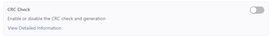
- Confirm the activation by selecting Enable. Or, Cancel to return to the DMF Features page.
Figure 19. Enable CRC Check 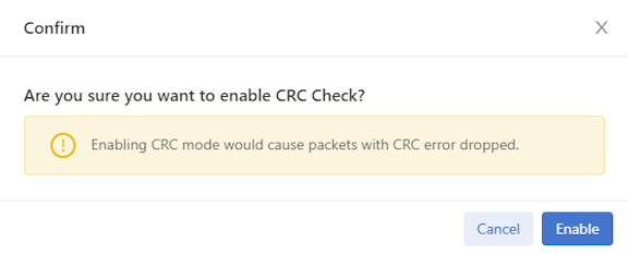
- CRC Check is running.
Figure 20. CRC Check Enabled 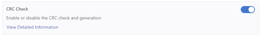
- To disable the feature, toggle the CRC Check to Off. Select Disable and confirm.
Figure 21. Disable CRC Check 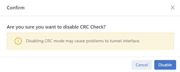 The feature card updates with the status.
Figure 22. CRC Check Disabled
Custom Priority
When custom priorities are allowed, non-admin users may assign policy priorities between 0 and 100 (the default value). However, when custom priorities are not allowed, the default priority of 100 will be automatically assigned to non-admin users' policies.
Enable and disable Custom Priority using the steps described in the following topics.
Configuring Custom Priority using the GUI
- Select the Custom Priority card.
Figure 23. Custom Priority Disabled 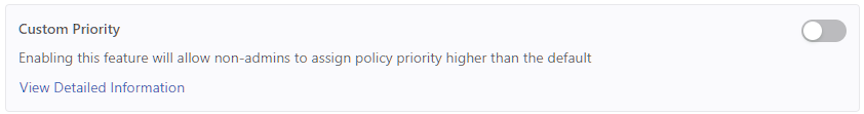
- Confirm the activation by selecting Enable. Or, Cancel to return to the DMF Features page.
Figure 24. Enable Custom Priority 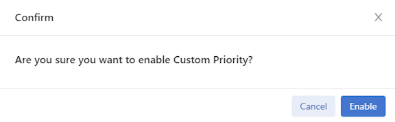
- Custom Priority is running.
Figure 25. Custom Priority Enabled 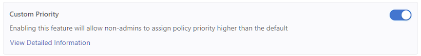
- To disable the feature, toggle the Custom Priority to Off. Select Disable and confirm.
Figure 26. Disable Custom Priority 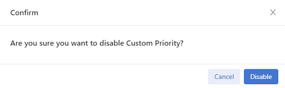
Configuring Custom Priority using the CLI
To enable the Custom Priority, enter the following command:
controller-1(config)# allow-custom-priority
To disable the Custom Priority, enter the following command:
controller-1(config)# no allow-custom-priority
Device Deployment Mode
Complete the fabric switch installation in one of the following two modes:
- Layer 2 Zero Touch Fabric (L2ZTF, Auto-discovery switch provisioning mode)
In this mode, switch software automatically discovers the Controller via IPv6 local link addresses and downloads and installs the appropriate Switch Light OS image from the Controller. This installation method requires all the fabric switches and the DMF Controller to be in the same Layer 2 network (IP subnet). Also, suppose the fabric switches need IPv4 addresses to communicate with SNMP or other external services. In that case, users must configure IPAM, which provides the Controller with a range of IPv4 addresses to allocate to the fabric switches.
- Layer 3 Zero Touch Fabric (L3ZTF, Preconfigured switch provisioning mode)
When fabric switches are in a different Layer 2 network from the Controller, log in to each switch individually to configure network information and download the ZTF installer. Subsequently, the switch automatically downloads Switch Light OS from the Controller. This mode requires communication between the Controller and the fabric switches using IPv4 addresses, and no IPAM configuration is required.
| Requirement | Layer 2 mode | Layer 3 mode |
|---|---|---|
| Any switch in a different subnet from the controller | No | Yes |
| IPAM configuration for SNMP and other IPv4 services | Yes | No |
| IP address assignment | IPv4 or IPv6 | IPv4 |
| Refer to this section (in User Guide) | Using L2 ZTF (Auto-Discovery) Provisioning Mode | Changing to Layer 3 (Pre-Configured) Switch Provisioning Mode |
All the fabric switches in a single fabric must be installed using the same mode. If users have any fabric switches in a different IP subnet than the Controller, users must use Layer 3 mode for installing all the switches, even those in the same Layer 2 network as the Controller. Installing switches in mixed mode, with some switches using ZTF in the same Layer 2 network as the Controller, while other switches in a different subnet are installed manually or using DHCP is unsupported.
Configuring Device Deployment Mode using the GUI
From the DMF Features page, proceed to the Device Deployment Mode feature card and perform the following steps to manage the feature.
- Select the Device Deployment Mode card.
Figure 28. Device Deployment Mode - Auto Discovery 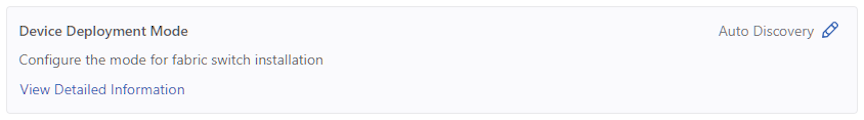
- Enter the edit mode using the pencil icon.
Figure 29. Configure Device Deployment Mode 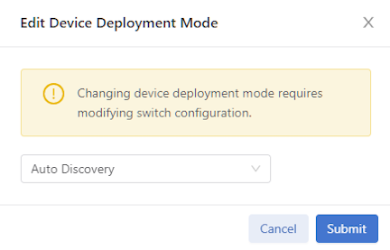
- Change the switching mode as required using the drop-down menu. The default mode is Auto Discovery.
Figure 30. Device Deployment Mode Options 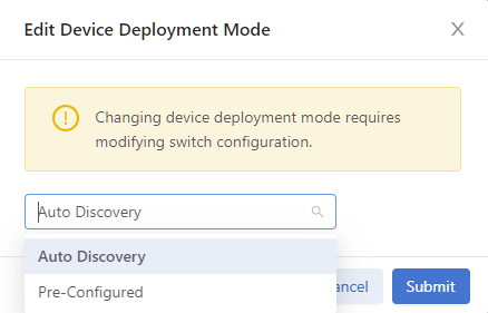
Figure 31. Device Deployment Mode - Pre-Configured Option 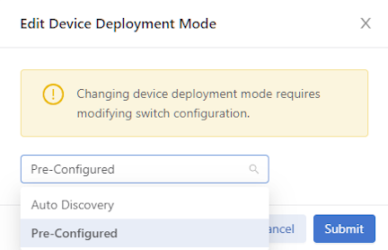
- The Device Deployment Mode status updates.
Figure 32. Device Deployment Mode - Status Update 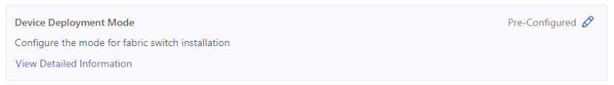
Configuring Device Deployment Mode using the CLI
controller-1(config)# deployment-mode auto-discovery

Changing device deployment mode requires modifying switch configuration. Enter "yes" (or "y") to continue: y
controller-1(config)# deployment-mode pre-configured

Changing device deployment mode requires modifying switch configuration. Enter "yes" (or "y") to continue: y
Inport Mask
Enable and disable Inport Mask using the steps described in the following topics.
Inport Mask using the CLI
DANZ Monitoring Fabric implements multiple flow optimizations to reduce the number of flows programmed in the DMF switch TCAM space. This feature enables effective usage of TCAM space, and it is on by default.
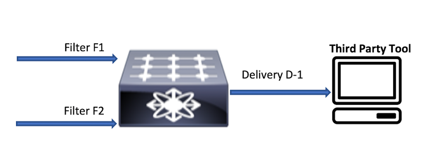
With inport mask optimization, only 10 rules are consumed. This feature optimizes TCAM usage at every level (filer, core, delivery) in the DMF network.
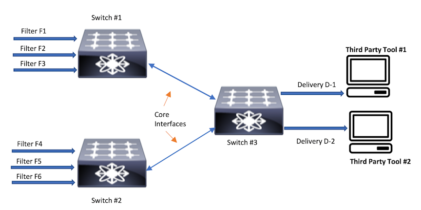
In this topology, if a policy has N rules without in-port optimization, the policy will consume 3N at Switch 1, 3N at Switch 2, and 2N at Switch 3. With the in-port optimization feature enabled, the policy consumes only N rules at each switch.
However, this feature loses granularity in the statistics available because there is only one set of flow mods for multiple filter ports per switch. Statistics without this feature are maintained per filter port per policy.
With inport optimization enabled, the statistics are combined for all input ports sharing rules on that switch. The option exists to obtain filter port statistics for different flow mods for each filter port. However, this requires disabling inport optimization, which is enabled by default.
controller-1(config)# controller-1(config)# no inport-mask
Inport Mask using the GUI
- Select the Inport Mask card.
Figure 35. Inport Mask Disabled 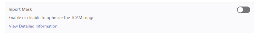
- Confirm the activation by selecting Enable. Or, Cancel to return to the DMF Features page.
Figure 36. Enable Inport Mask 
- Inport Mask is running.
Figure 37. Inport Mask Enabled 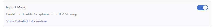
- To disable the feature, toggle the Inport Mask to Off. Select Disable and confirm.
Figure 38. Disable Inport Mask 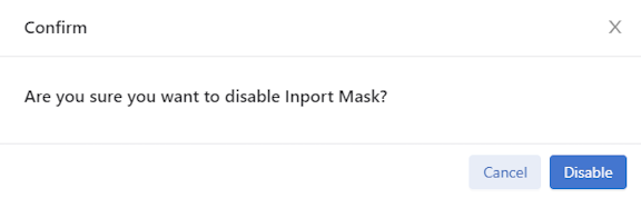
Match Mode
- L3-L4 mode (default mode): With L3-L4 mode, fields other than
src-macanddst-maccan be used for specifying policies. If no policies usesrc-macordst-mac, the L3-L4 mode allows more match rules per switch. - Full-match mode: With full-match mode, all matching fields, including
src-macanddst-mac, can be used while specifying policies. - L3-L4 Offset mode: L3-L4 offset mode allows matching beyond the L4 header up to 128 bytes from the beginning of the packet. The number of matches per switch in this mode is the same as in full-match mode. As with L3-L4 mode, matches using
src-macanddst-macare not permitted.Note: Changing switching modes causes all fabric switches to disconnect and reconnect with the Controller. Also, all existing policies will be reinstalled. The switching mode applies to all DMF switches in the DANZ Monitoring Fabric. Switching between modes is possible, but any match rules incompatible with the new mode will fail.
Setting the Match Mode Using the CLI
controller-1(config)# match-mode {full-match | l3-l4-match | l3-l4-offset-match}
controller-1(config)# match-mode full-match
Setting the Match Mode Using the GUI
From the DMF Features page, proceed to the Match Mode feature card and perform the following steps to enable the feature.
- Select the Match Mode card.
Figure 40. L3-L4 Match Mode 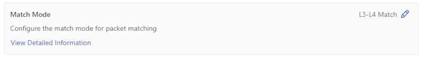
- Enter the edit mode using the pencil icon.
Figure 41. Configure Switching Mode 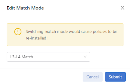
- Change the switching mode as required using the drop-down menu. The default mode is L3-L4 Match.
Figure 42. L3-L4 Match Options 
Retain User Policy VLAN
Enable and disable Retain User Policy VLAN using the steps described in the following topics.
Retain User Policy VLAN using the CLI
This feature will send traffic to a delivery interface with the user policy VLAN tag instead of the overlap dynamic policy VLAN tag for traffic matching the dynamic overlap policy only. This feature is supported only in push-per-policy mode. For example, policy P1 with filter interface F1 and delivery interface D1, and policy P2 with filter interface F1 and delivery interface D2, and overlap dynamic policy P1_o_P2 is created when the overlap policy condition is met. In this case, the overlap dynamic policy is created with filter interface F1 and delivery interfaces D1 and D2. The user policy P1 assigns a VLAN (VLAN 10) and P2 assigns a VLAN (VLAN 20) when it is created, and the overlap policy also assigns a VLAN (VLAN 30) when it is dynamically created. When this feature is enabled, traffic forwarded to D1 will have a policy VLAN tag of P1 (VLAN 10) and D2 will have a policy VLAN tag of policy P2 (VLAN 20). When this feature is disabled, traffic forwarded to D1 and D2 will have the dynamic overlap policy VLAN tag (VLAN 30). By default, this feature is disabled.
Feature Limitations:
- An overlap dynamic policy will fail when the overlap policy has filter (F1) and delivery interface (D1) on the same switch (switch A) and another delivery interface (D2) on another switch (switch B).
- Post-to-delivery dynamic policy will fail when it has a filter interface (F1) and a delivery interface (D1) on the same switch (switch A) and another delivery interface (D2) on another switch (switch B).
- Overlap policies may be reinstalled when a fabric port goes up or down when this feature is enabled.
- Double-tagged VLAN traffic is not supported and is dropped at the delivery interface.
- Tunnel interfaces are not supported with this feature.
- Only IPv4 traffic is supported; other non-IPv4 traffic is dropped at the delivery interface.
- Delivery interfaces with IP addresses (L3 delivery interfaces) are not supported.
- This feature is not supported on EOS switches (Arista 7280 switches).
- Delivery interface statistics may not be accurate when displayed using the sh policy command. This will happen when policy P1 has F1, D1, D2 and policy P2 has F1, D2. In this case, overlap policy P1_o_P2 is created with delivery interfaces D1, D2. Since D2 is in both policies P1 and P2, overlap traffic is forwarded to D2 with both the P1 policy VLAN and the P2 policy VLAN. The sh policy policy_name command will not show this doubling of traffic on delivery interface D2. Delivery interface statistics will show this extra traffic forwarded from the delivery interface.
controller-1(config)# retain-user-policy-vlan
This will enable retain-user-policy-vlan feature. Non-IP packets will be dropped at delivery. Enter
"yes" (or "y") to continue: yes
controller-1> show fabric
~~~~~~~~~~~~~~~~~~~~~~~~~ Aggregate Network State ~~~~~~~~~~~~~~~~~~~~~~~~~
Number of switches : 14
Inport masking : True
Number of unmanaged services : 0
Number of switches with service interfaces : 0
Match mode : l3-l4-offset-match
Number of switches with delivery interfaces : 11
Filter efficiency : 1:1
Uptime : 4 days, 8 hours
Max overlap policies (0=disable) : 10
Auto Delivery Interface Strip VLAN : True
Number of core interfaces : 134
State : Enabled
Max delivery BW (bps) : 2.18Tbps
Health : unhealthy
Track hosts : True
Number of filter interfaces : 70
Number of policies : 101
Start time : 2022-02-28 16:18:01.807000 UTC
Number of delivery interfaces : 104
Retain User Policy Vlan : True
Use this feature with the strip-second-vlan option during delivery interface configuration to preserve the outer DMF fabric policy VLAN, strip the inner VLAN of traffic forwarded to a tool, or the strip-no-vlan option during delivery interface configuration.
Retain User Policy VLAN using the GUI
- Select the Retain User Policy VLAN card.
Figure 43. Retain User Policy VLAN Disabled 
- Confirm the activation by selecting Enable. Or, Cancel to return to the DMF Features page.
Figure 44. Enable Retain User Policy VLAN 
- Retain User Policy VLAN is running.
Figure 45. Retain User Policy VLAN Enabled 
- To disable the feature, toggle the Retain User Policy VLAN to Off. Select Disable and confirm.
Figure 46. Disable Retain User Policy VLAN 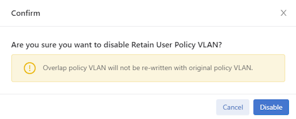 The feature card updates with the status.
Figure 47. Retain User Policy VLAN Disabled
Tunneling
For more information about Tunneling please refer to the Understanding Tunneling section.
Enable and disable Tunneling using the steps described in the following topics.
Configuring Tunneling using the GUI
- Select the Tunneling card.
Figure 48. Tunneling Disabled 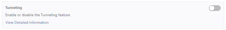
- Confirm the activation by selecting Enable. Or, Cancel to return to the DMF Features page.
Figure 49. Enable Tunneling 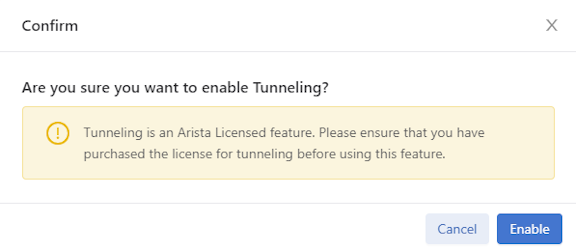 Note: CRC Check must be running before attempting to enable Tunneling. An error message displays if CRC Check is not enabled. Proceeding to select Enable results in a validation error message. Refer to the CRC Check section for more information on configuring the CRC Check feature.
Figure 50. CRC Check Warning Message 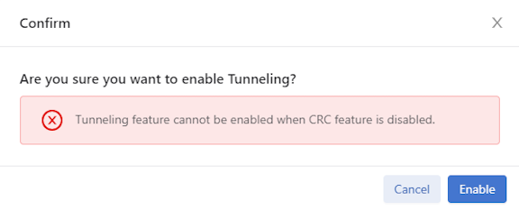
- Tunneling VLAN is running.
Figure 51. Tunneling Enabled 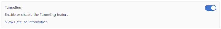
- To disable the feature, toggle Tunneling to Off. Select Disable and confirm.
Figure 52. Disable Tunneling 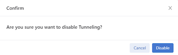 The feature card updates with the status.
Figure 53. Tunneling VLAN Disabled
Configuring Tunneling using the CLI
controller-1(config)# tunneling

Tunneling is an Arista Licensed feature.
Please ensure that you have purchased the license for tunneling before using this feature.
Enter "yes" (or "y") to continue: y
controller-1(config)#
controller-1(config)# no tunneling
This would disable tunneling feature? Enter "yes" (or "y") to continue: y
controller-1(config)#
VLAN Preservation
In DANZ Monitoring Fabric (DMF), metadata is appended to the packets forwarded by the fabric to a tool attached to a delivery interface. This metadata is encoded primarily in the outer VLAN tag of the packets.
By default (using the auto-delivery-strip feature), this outer VLAN tag is always removed on egress upon delivery to a tool.
The VLAN preservation feature introduces a choice to selectively preserve a packet's outer VLAN tag instead of stripping or preserving all of it.
VLAN preservation works in both push-per-filter and push-per-policy mode for auto-assigned and user-configured VLANs.
This functionality only supports 2000 VLAN IDs and port combinations per switch.
Support for VLAN preservation is on select Broadcom® switch ASICs. Ensure your switch model supports this feature before attempting to configure it.
Configure VLAN Preservation
Global Configuration
- To view or edit the global configuration, navigate to the DANZ Monitoring Fabric (DMF) Features page by selecting the gear icon in the navigation bar.
Figure 54. DMF Menu Bar  The DMF Feature allows for managing fabric-wide settings for DMF.
 - Scroll to the VLAN Preservation card.
Figure 55. DMF Features Page 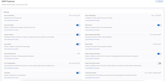
Figure 56. VLAN Preservation Card 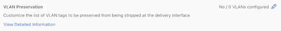
- Select Edit (pencil icon) to configure or modify the global VLAN Preservation feature settings.
Figure 57. Edit VLAN Preservation Configuration 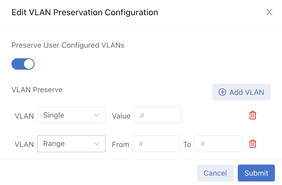 The edit screen has two input sections:
- Toggle on or off the Preserve User Configured VLANs.
- Enter the parameters for VLAN Preserve using the following functions:
- Use + Add VLAN to add VLAN IDs.
- Select the Single VLAN type drop-down to add a single VLAN ID.
- Select the Range VLAN type drop-down to add a continuous VLAN ID range.
- Use the Trash icon (delete) to delete a single VLAN ID or a VLAN ID range.
Local Configuration
- The VLAN Preservation configuration can be applied per-delivery interface while configuring or editing a delivery or filter-and-delivery interface in DMF Interfaces and .
Figure 58. Monitoring Interfaces Delivery Interface Create Interface 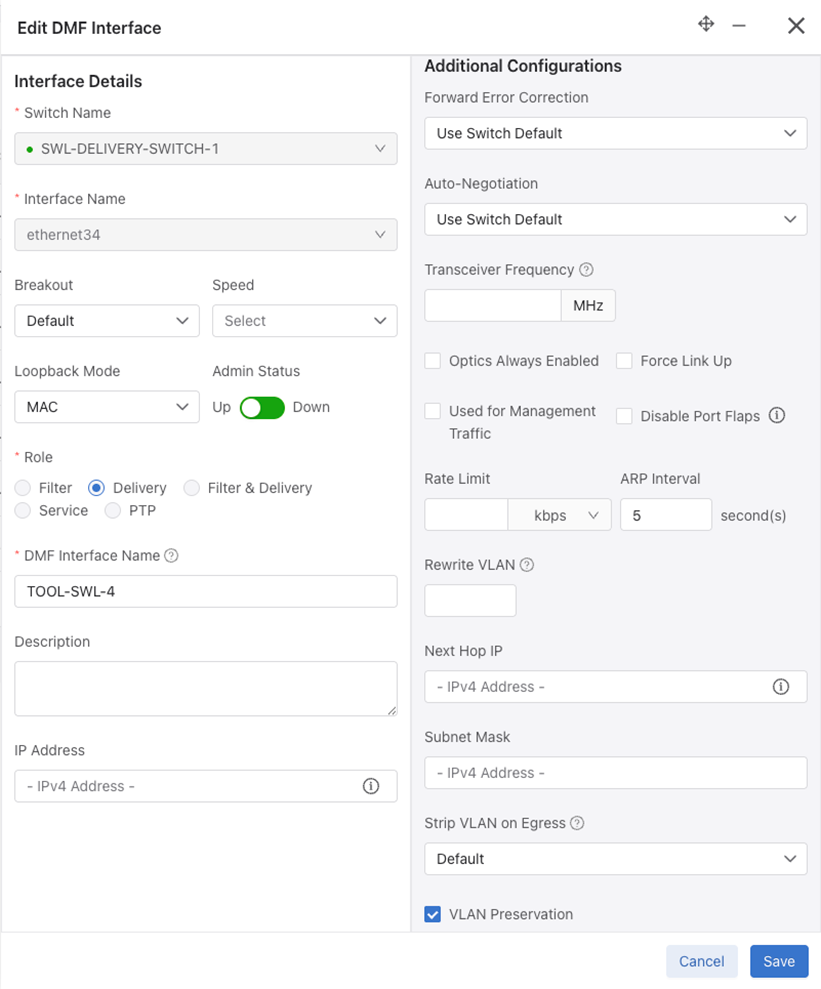
VLAN Preservation for MLAG Delivery Interfaces
- Configure VLAN preservation for MLAG delivery interfaces using the FabricMLAGs page while configuring an MLAG Domain toggling the VLAN Preservation and Preserve User Configured VLANs switches to on (as required).
Figure 59. Create MLAG Domain 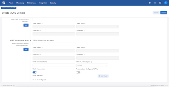
Figure 60. MLAG VLAN Preservation & Preserve User Configured VLANs (expanded view) 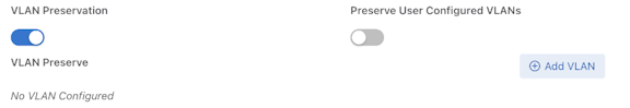
Using the CLI to Configure VLAN Preservation
Configure VLAN preservation at two levels: global and local. A local configuration can override the global configuration.
Global Configuration
Enable VLAN preservation globally using the vlan-preservation command from the config submode to apply aglobal configuration.
(config)# vlan-preservation
config-vlan-preservation submode:
- preserve-user-configured-vlans
- preserve-vlans
Use the help function to list the options by entering a ? (question mark).
(config-vlan-preservation)# ?
Commands:
preserve-user-configured-vlans     Preserve all user-configured VLANs for all delivery interfaces
preserve-vlan                      Configure VLAN ID to preserve for all delivery interfaces
Use the preserve-user-configured-vlans option to preserve all user-configured VLANs. The packets with the user-configured VLANs will have their fabric-applied VLAN tags preserved even after leaving the respective delivery interface.
(config-vlan-preservation)# preserve-user-configured-vlans
Use the preserve-vlan option to specify and preserve a particular VLAN ID. Any VLAN ID may be provided. In the following example, the packets with VLAN ID 100 or 200 will have their fabric-applied VLAN tags preserved upon delivery to the tool.
(config-vlan-preservation)# preserve-vlan 100
(config-vlan-preservation)# preserve-vlan 200
Local Configuration
This feature applies to delivery and both-filter-and-delivery interface roles.
Fabric-applied VLAN tag preservation can be enabled locally on each delivery interface as an alternative to the global VLAN preservation configuration. To enable this functionality locally, enter the following configuration submode using the if-vlan-preservation command to specify either one of the two available options. Use the help function to list the options by entering a ? (question mark).
(config-switch-if)# if-vlan-preservation
(config-switch-if-vlan-preservation)# ?
Commands:
preserve-user-configured-vlans     Preserve all user-configured VLANs for all delivery interfaces
preserve-vlan                      Configure VLAN ID to preserve for all delivery interfaces
Use the preserve-user-configured-vlans option to preserve all user-configured VLAN IDs in push-per-policy or push-per-filter mode on a selected delivery interface. All packets egressing such delivery interface will have their user-configured fabric VLAN tags preserved.
(config-switch-if-vlan-preservation)# preserve-user-configured-vlans
Use the preserve-vlan option to specify and preserve a particular VLAN ID. For example, if any packets with VLAN ID 100 or 300 egress the selected delivery interface, VLAN IDs 100 and 300 will be preserved.
(config-switch-if-vlan-preservation)# preserve-vlan 100
(config-switch-if-vlan-preservation)# preserve-vlan 300
On an MLAG delivery interface, the local configuration follows the same model, as shown below.
(config-mlag-domain-if)# if-vlan-preservation member role
(config-mlag-domain-if)# if-vlan-preservation
(config-mlag-domain-if-vlan-preservation)# preserve-user-configured-vlans preserve-vlan
To disable selective VLAN preservation for a particular delivery or both-filter-and-delivery interface, use the following command to disable the feature's global and local configuration for the selected interface:
(config-switch-if)# role delivery interface-name del
<cr>                 no-analytics          strip-no-vlan         strip-second-vlan
ip-address            no-vlan-preservation  strip-one-vlan        strip-two-vlan
(config-switch-if)# role delivery interface-name del no-vlan-preservation
CLI Show Commands
The following show command displays the device name on which VLAN preservation is enabled and the information about which VLAN is preserved on specific selected ports. Use the data in this table primarily for debugging purposes.
# show switch all table vlan-preserve
# Vlan-preserve Device name Entry key
-|-------------|-----------|----------------------|
1 0             delivery1   VlanVid(0x64), Port(6)
2 0             filter1     VlanVid(0x64), Port(6)
3 0             core1       VlanVid(0x64), Port(6)
Troubleshooting
Reuse of Policy VLANs
Policies can reuse VLANs for policies in different switch islands. A switch island is an isolated fabric managed by a single pair of controllers; there is no data plane connection between fabrics in different switch islands. For example, with a single Controller pair managing six switches (switch1, switch2, switch3, switch4, switch5, and switch6 the option exists to create two fabrics with three switches each (switch1, switch2, switch3 in one switch island and switch4, switch5, and switch6 in another switch island), as long as there is no data plane connection between switches in the different switch islands.
There is no command needed to enable this feature. If the above condition is met, creating policies in each switch island with the same policy VLAN tag is supported.
In the condition mentioned above, assign the same policy VLAN to two policies in different switch islands using the push-vlan vlan-tag command under policy configuration. For example, policy P1 in switch island 1 assigned push-vlan 10, and policy P2 in switch island 2 assigned the same vlan tag 10 using push-vlan 10 under policy configuration.
When a data plane link connects two switch islands, it becomes one switch island. In that case, two policies cannot use the same policy vlan tag, so one of the policies (P1 or P2) will become inactive.
Rewriting the VLAN ID for a Filter Interface
TAP-PORT-1 to Ethernet interface 10.
controller-1(config)# switch f-switch1
controller-1(config-switch-if)# interface ethernet10
controller-1(config-switch-if)# role filter interface-name TAP-PORT-1 rewrite vlan 100
Reusing Filter Interface VLAN IDs
A DMF fabric comprises groups of switches, known as islands, connected over the data plane. There are no data plane connections between switches in different islands. When Push-Per-Filter forwarding is enabled, monitored traffic is forwarded within an island using the VLAN ID affiliated with a Filter Interface. These VLAN IDs are configurable. Previously, the only recommended configuration was for these VLAN IDs to be globally unique.
This feature adds official support for associating the same VLAN ID with multiple Filter Interfaces as long as they are in different islands. This feature provides more flexibility when duplicating Filter Interface configurations across islands and helps prevent using all available VLAN IDs.
Note that within each island, VLAN IDs must still be unique, which means that Filter Interfaces in the same group of switches cannot have the same ID. When trying to reuse the same VLAN ID within an island, DMF generates a fabric error, and only the first Filter Interface (as sorted alphanumerically by DMF name) remains in use.
Configuration
This feature requires no special configuration beyond the existing Filter Interface configuration workflow.
Troubleshooting
A fabric error occurs if the same VLAN ID is configured more than once in the same island. The error message includes the Filter Interface name, the switch name, and the VLAN ID that is not unique. When encountering this error, pick a different non-conflicting VLAN ID.
Filter Interface invalid VLAN errors can be displayed in the CLI using the following command: 
The following is a vertical representation of the CLI output above for illustrative purposes only.
>show fabric errors filter-interface-invalid-vlan
~~ Invalid Filter Interface VLAN(s) ~~
#               1
DMF Name        filter1-f1
IF Name         ethernet2
Switch          filter1 (00:00:52:54:00:4b:c9:bc)
Rewrite VLAN    1
Details         The configured rewrite VLAN 1 for filter interface filter1-f1
                is not unique within its fabric.
>show debug switch-cluster
# Member
-|--------------|
1 core1, filter1
>show link all
~~~~~~~~~~~~~~~~~~~~~~~~~~~~~~~~~~~~~~~~~~~~ Links ~~~~~~~~~~~~~~~~~~~~~~~~~~~~~~~~~~~~~~~~~~~~
# Active State Src switch Src IF Name Dst switch Dst IF Name Link Type Since
-|------------|----------|-----------|----------|-----------|---------|-----------------------|
1 active       filter1    ethernet1   core1      ethernet1   normal    2023-05-24 22:31:39 UTC
2 active       core1      ethernet1   filter1    ethernet1   normal    2023-05-24 22:31:40 UTC
Considerations
- VLAN IDs must be unique within an island. Filter Interfaces in the same island with the same VLAN ID are not supported.
- This feature only applies to manually configured Filter Interface VLAN IDs. VLAN IDs that are automatically assigned are still unique across the entire fabric.
Using Push-per-filter Mode
The push-per-filter mode setting does not enable tag-based forwarding. Each filter interface is automatically assigned a VLAN ID; the default range is 1 to 4094. To change the range, use the auto-vlan-range command.
The option exists to manually assign a VLAN not included in the defined range to a filter interface.
To manually assign a VLAN to a filter interface in push-per-filter mode, complete the following steps:
Tag-based Forwarding
The DANZ Monitoring Fabric (DMF) Controller configures each switch with forwarding paths based on the most efficient links between the incoming filter interface and the delivery interface, which is connected to analysis tools. The TCAM capacity of the fabric switches may limit the number of policies to configure. The Controller can also use VLAN tag-based forwarding, which reduces the TCAM resources required to implement a policy.
Tag-based forwarding is automatically enabled when the auto-VLAN Mode is push-per-policy, which is the default. This configuration improves traffic forwarding within the monitoring fabric. DMF uses the assigned VLAN tags to forward traffic to the correct delivery interface, saving TCAM space. This feature is handy when using switches based on the Tomahawk chipset because these switches have higher throughput but reduced TCAM space.
Policy Rule Optimization
Prefix Optimization
A policy can match with a large number of IPv4 or IPv6 addresses. These matches can be configured explicitly on each match rule, or the match rules can use an address group. With prefix optimization based on IPv4, IPv6, and TCP ports, DANZ Monitoring Fabric (DMF) uses efficient masking algorithms to minimize the number of flow entries in hardware.
controller-1(config)# policy ip-addr-optimization
                controller-1(config-policy)# action forward
                controller-1(config-policy)# delivery-interface TOOL-PORT-1
                controller-1(config-policy)# filter-interface TAP-PORT-1
                controller-1(config-policy)# 10 match ip dst-ip 1.1.1.0 255.255.255.255
                controller-1(config-policy)# 11 match ip dst-ip 1.1.1.1 255.255.255.255
                controller-1(config-policy)# 12 match ip dst-ip 1.1.1.2 255.255.255.255
                controller-1(config-policy)# 13 match ip dst-ip 1.1.1.3 255.255.255.255
                controller-1(config-policy)# show policy ip-addr-optimization optimized-match
                Optimized Matches :
                10 ether-type 2048 dst-ip 1.1.1.0 255.255.255.252
controller-1(config)# policy ip-addr-optimization
                controller-1(config-policy)# action forward
                controller-1(config-policy)# delivery-interface TOOL-PORT-1
                controller-1(config-policy)# filter-interface TAP-PORT-1
                controller-1(config-policy)# 10 match ip dst-ip 1.1.1.0 255.255.255.255
                controller-1(config-policy)# 11 match ip dst-ip 1.1.1.1 255.255.255.255
                controller-1(config-policy)# 12 match ip dst-ip 1.1.1.2 255.255.255.255
                controller-1(config-policy)# 13 match ip dst-ip 1.1.1.3 255.255.255.255
                controller-1(config-policy)# 100 match ip dst-ip 1.1.0.0 255.255.0.0
                controller-1(config-policy)# show policy ip-addr-optimization optimized-match
                Optimized Matches :
                100 ether-type 2048 dst-ip 1.1.0.0 255.255.0.0
controller-1(config)# policy ip-addr-optimization
                controller-1(config-policy)# 25 match ip6 src-ip 2001::100:100:100:0 FFFF:FFFF:FFFF::0:0
                controller-1(config-policy)# 30 match ip6 src-ip 2001::100:100:100:0 FFFF:FFFF::0
                controller-1(config-policy)# show policy ip-addr-optimization optimized-match
                Optimized Matches :
                30 ether-type 34525 src-ip 2001::100:100:100:0 FFFF:FFFF::0
controller-1(config)# policy ip-addr-optimization
                controller-1(config-policy)# 10 match ip dst-ip 2.1.0.0 255.255.0.0
                controller-1(config-policy)# 11 match ip dst-ip 3.1.0.0 255.255.0.0
                controller-1(config-policy)# show policy ip-addr-optimization optimized-match
                Optimized Matches : 10 ether-type 2048 dst-ip 2.1.0.0 254.255.0.0
Transport Port Range and VLAN Range Optimization
The DANZ Monitoring Fabric (DMF) optimizes transport port ranges and VLAN ranges within a single match rule. Improvements in DMF now support cross-match rule optimization.
Show Commands
To view the optimized match rule, use the show command:
# show policy policy-name optimized-match
To view the configured match rules, use the following command:
# show running-config policy policy-name
Consider the following DMF policy configuration.
# show running-config policy p1
! policy
policy p1
action forward
delivery-interface d1
filter-interface f1
1 match ip vlan-id-range 1 4
2 match ip vlan-id-range 5 8
3 match ip vlan-id-range 7 16
4 match ip vlan-id-range 10 12
With the above policy configuration and before the DMF 8.5.0 release, the four match conditions would be optimized into the following TCAM rules:
# show policy p1 optimized-match
Optimized Matches :
1 ether-type 2048 vlan 0 vlan-mask 4092
1 ether-type 2048 vlan 4 vlan-mask 4095
2 ether-type 2048 vlan 5 vlan-mask 4095
2 ether-type 2048 vlan 6 vlan-mask 4094
3 ether-type 2048 vlan 16 vlan-mask 4095
3 ether-type 2048 vlan 8 vlan-mask 4088
However, with the cross-match rule optimizations introduced in this release, the rules installed in the switch would further optimize TCAM usage, resulting in:
# show policy p1 optimized-match
Optimized Matches :
1 ether-type 2048 vlan 0 vlan-mask 4080
1 ether-type 2048 vlan 16 vlan-mask 4095
A similar optimization technique applies to L4 ports in match conditions:
# show running-config policy p1
! policy
policy p1
action forward
delivery-interface d1
filter-interface f1
1 match tcp range-src-port 1 4
2 match tcp range-src-port 5 8
3 match tcp range-src-port 7 16
4 match tcp range-src-port 9 14

# show policy p1 optimized-match
Optimized Matches :
1 ether-type 2048 ip-proto 6 src-port 0 -16
1 ether-type 2048 ip-proto 6 src-port 16 -1
Match Rule Field Set Optimization
When several IP addresses are used in a single policy (whether via an address group or individually across match rules with otherwise identical conditions), the Controller groups the addresses together and programs them as a field set on supported switches.
TCAM directly references the field set label, enabling entry matching against packets containing any associated IP prefixes. This optimization dramatically reduces TCAM consumption for policies involving numerous addresses, facilitating the programming of significantly more policies or addresses without exceeding hardware capacity limits.
For example, on a switch incapable of performing this optimization, a policy matching traffic from a 100-entry source address group to a 100-entry destination address group would require 100x100=10,000 individual entries. With this optimization, the Controller programs two field sets and a single match rule that references both, reducing TCAM consumption for that policy from 10,000 entries to just 1.
The following switches support Match Rule Field Set Optimization:
- 7280R3 series
- 7280R3A series
- 7800R3
Configuration
No configuration is necessary. This feature operates automatically during rule installation on supported hardware. The Controller selects field set optimization based on the specific rules and the destination switch.
Show Commands
Running the following command confirms switch support by verifying that Aegis Field Set Supported displays True within the switch properties:
dmf-controller # show switch switch-name property
Switch                               : switch-name
…
Aegis Field Set Supported            : True
…
Troubleshooting
The following commands facilitate troubleshooting.
Use the show switch switch-name table contents
ingress-flow-2 command to display rules programmed to a switch:
dmf-controller(config-policy)# show switch switch-name table contents ingress-flow-2
~~~~~~~~~~~~~~~~~~~~~~~~~~~~~~~~~~~~~~~~~~~~~~~~~~~~~ Ingress-flow-2s ~~~~~~~~~~~~~~~~~~~~~~~~~~~~~~~~~~~~~~~~~~~~~~~~~~~~~~~~~~~~~~~~~~~~~~~~~~~~~
# Ingress-flow-2 Device name Entry key                                                                                               Entry value
-|--------------|-----------|-------------------------------------------------------------------------------------------------------|-----------------|
1 0              sw          Priority(6400), Port(1701), EthType(2048), FieldSetMatch(mtype=BSN_FIELD_SET_MATCH_IPV4_SRC, name=[52]) Name(test), …
Alternately, use the show policy <policy-name> flow command:
dmf-controller(config-policy)# show policy policy-name flow
~~~~~~~~~~~~~~~~~~~~~~~~~~~~~~~~~~~~~~~~~~~~~~~~~~~~~~~~~~~~~~ Policy Flow Info ~~~~~~~~~~~~~~~~~~~~~~~~~~~~~~~~~~~~~~~~~~~
# Policy Switch Pkt/s Bit/s Priority In-Ports Match                                         Instructions
-|------|------|-----|-----|--------|--------|---------------------------------------------|-------------------------------------|
1 test   sw     0.0   -              1701     ether-type 2048,ipv4-src ipv4-src field-set 4 apply: name=<policy-name> push-vlan: ...

~~~~~~ Policy Match Rule & Flow Correlation  ~~~~~~
# Policy Switch Flow Related Policy Policy Matches
-|------|------|---|--------------|--------------|
1 test   sw     #1  test           1
The following command displays the contents of a field set on a switch. Matching names facilitate correlation across outputs. The name in the field-set and ingress-flow-2 output represents the byte values of the string shown in the show policy
policy-name flow output.
For instance, the Unicode character 4 in the earlier show policy policy-name flow policy flow output corresponds to name=[52] in the following field set output.
dmf=controller (config-policy)# show switch switch-name table contents field-set
~~~~~~~~~~~~~~~~~~~~~~~~~~~~~~~~~~~~~~~~~~~~~~~~~~~~~~~~~~~~~~~~~~~~~~~~~~~~~~ Field-sets ~~~~~~~~~~~~~~~~~~~~~~~~~~~~~~~~~~~~~~~~~~
# Field-set Device name Entry key                                      Entry value
-|---------|-----------|----------------------------------------------|----------------------------------------------------------------------------|
1 0         sw          FieldSet(fstype=BSN_FIELD_SET_IPV4, name=[52]) Ipv4Prefix(10.0.0.2, prefixLength=31), Ipv4Prefix(10.0.0.8, prefixLength=32)
Examples
Policy P1 with filter interface F1 and delivery interface D1 on a 7280R3 switch switch1 with 5 rules as shown in the following.
policy P1
  action forward
  delivery-interface D1
  filter-interface F1
  1 match full ether-type ip src-ip 192.168.23.10
  2 match full ether-type ip src-ip 78.1.32.20
  3 match full ether-type ip protocol 6 range-src-ip 30.1.1.0 30.1.1.100 src-port 443
  4 match full ether-type ip protocol 6 src-port 8080
  5 match full ether-type ip protocol 6 src-port 22
Previous DMF releases would have installed 8 TCAM entries on a 7280R3 switch for the example policy. The current release installs only four TCAM entries by utilizing the Aegis field-set optimization feature.
dmf-controller(config)# sh policy P1 flow
~~~~~~~~~~~~~~~~~~~~~~~~~~~~~~~~~~~~~~~~~~~~~~~~~~~~~~~~~~~~~~~~~~~~~~~~~~~~~~~~~~~~~~~~~~~~~~~~~~~~~~~~~~~~~~~~~~~~~~~~~~~~~ Policy Flow Info ~~~~~~~~~~~~~~~~~~~~~~~~~~~~~~~~~~~~~~~~~~~~~~~~~~~~~~~~~~~~~~~~~~~~~~~~~~~~~~~~~~~~~~~~~~~~~~~~~~~~~~~~~~~~~~~~~~~~~~~~~~~~~
# Policy Switch  Pkt/s Bit/s Priority In-Ports Match                                                                            Instructions
-|------|-------|-----|-----|--------|--------|--------------------------------------------------------------------------------|-------------------------------------------------------------------------------------------------------------------------------------------|
1 P1     switch1 0.0   -              7        ether-type 2048,ip-proto 6,tcp-port-src 22/65535                                 apply: name=P1 push-vlan: ethertype=802.1Q,set-field: match-field/type=vlan-vid, match-field/vlan-tag=179,output: max-length=65535, port=12
2 P1     switch1 0.0   -              7        ether-type 2048,ipv4-src ipv4-src field-set 7E                                   apply: name=P1 push-vlan: ethertype=802.1Q,set-field: match-field/type=vlan-vid, match-field/vlan-tag=179,output: max-length=65535, port=12
3 P1     switch1 0.0   -              7        ether-type 2048,ip-proto 6,ipv4-src ipv4-src field-set 7F,tcp-port-src 443/65535 apply: name=P1 push-vlan: ethertype=802.1Q,set-field: match-field/type=vlan-vid, match-field/vlan-tag=179,output: max-length=65535, port=12
4 P1     switch1 0.0   -              7        ether-type 2048,ip-proto 6,tcp-port-src 8080/65535                               apply: name=P1 push-vlan: ethertype=802.1Q,set-field: match-field/type=vlan-vid, match-field/vlan-tag=179,output: max-length=65535, port=12

~~~~~~~ Policy Match Rule & Flow Correlation ~~~~~~~
# Policy Switch  Flow Related Policy Policy Matches
-|------|-------|---|--------------|--------------|
1 P1     switch1 #1  P1             4, 5
2 P1     switch1 #2  P1             1, 2
3 P1     switch1 #3  P1             3
4 P1     switch1 #4  P1             4, 5
Aegis field set 1 is used for match rule 1 and 2 for source ip address 78.1.32.20 and 192.168.23.10. Aegis field set 2 is used for match rule for range-src-ip 30.1.1.0 to 30.1.1.100.
dmf-controller(config)# sh switch switch1 table contents field-set
~~~~~~~~~~~~~~~~~~~~~~~~~~~~~~~~~~~~~~~~~~~~~~~~~~~~~~~~~~~~~~~~~~~~~~~~~~~~~~~~~~~~~~~~~~~~~~~~~~~~~~~~~~~~~~~ Field-sets ~~~~~~~~~~~~~~~~~~~~~~~~~~~~~~~~~~~~~~~~~~~~~~~~~~~~~~~~~~~~~~~~~~~~~~~~~~~~~~~~~~~~~~~~~~~~~~~~~~~~~~~~~~~~~~~
# Field-set Device name Entry key                                          Entry value
-|---------|-----------|--------------------------------------------------|--------------------------------------------------------------------------------------------------------------------------------------------------------------|
1 0         switch1     FieldSet(fstype=BSN_FIELD_SET_IPV4, name=[55, 69]) Ipv4Prefix(78.1.32.20, prefixLength=32), Ipv4Prefix(192.168.23.10, prefixLength=32)
2 1         switch1     FieldSet(fstype=BSN_FIELD_SET_IPV4, name=[55, 70]) Ipv4Prefix(30.1.1.96, prefixLength=30), Ipv4Prefix(30.1.1.100, prefixLength=32), Ipv4Prefix(30.1.1.0, prefixLength=26), Ipv4Prefix(30.1.1.64, prefixLength=27)
dmf-controller(config)# sh switch switch1 table contents ingress-flow-2
~~~~~~~~~~~~~~~~~~~~~~~~~~~~~~~~~~~~~~~~~~~~~~~~~~~~~~~~~~~~~~~~~~~~~~~~~~~~~~~~~~~~~~~~~~~~~~~~~~~~~~~~~~~~~~~~~ Ingress-flow-2s ~~~~~~~~~~~~~~~~~~~~~~~~~~~~~~~~~~~~~~~~~~~~~~~~~~~~~~~~~~~~~~~~~~~~~~~~~~~~~~~~~~~~~~~~~~~~~~~~~~~~~~~~~~~~~~~~~
# Ingress-flow-2 Device name Entry key                                                                                                                         Entry value
-|--------------|-----------|---------------------------------------------------------------------------------------------------------------------------------|-----------------------------------------------------------------------------------|
1 0              switch1     Priority(6400), Port(7), EthType(2048), IpProto(6), TcpSrc(8080)                                                                  Name(P1), Data([0, 0, 6, 81]), PushVlanOnIngress(flags=[]), VlanVid(0xb3), Port(12)
2 1              switch1     Priority(6400), Port(7), EthType(2048), IpProto(6), TcpSrc(22)                                                                    Name(P1), Data([0, 0, 6, 82]), PushVlanOnIngress(flags=[]), VlanVid(0xb3), Port(12)
3 2              switch1     Priority(6400), Port(7), EthType(2048), FieldSetMatch(mtype=BSN_FIELD_SET_MATCH_IPV4_SRC, name=[55, 69])                          Name(P1), Data([0, 0, 6, 78]), PushVlanOnIngress(flags=[]), VlanVid(0xb3), Port(12)
4 3              switch1     Priority(6400), Port(7), EthType(2048), IpProto(6), FieldSetMatch(mtype=BSN_FIELD_SET_MATCH_IPV4_SRC, name=[55, 70]), TcpSrc(443) Name(P1), Data([0, 0, 6, 79]), PushVlanOnIngress(flags=[]), VlanVid(0xb3), Port(12)
Use the following commands to view TCAM entries and field set in a 7280R3 EOS switch:
switch1# sh management dmf flow summary
Flow tables:

Table              Total Flows      Programmed      Pending   Failed
--------------- ---------------- --------------- ------------ ------
Ingress 1                    0               0            0        0
Ingress 2                    4               4            0        0
Egress 1                     0               0            0        0
switch1# sh management dmf flow ingress 2 brief
Total flows: 4
Programmed: 4
Pending: 0
Failed: 0
Flows:

4 [ipv4] protocol tcp source port ssh destination port all in:Et7 setOuterVlan:179;Et12 [0/0] [S]
3 [ipv4] protocol tcp source port 8080 destination port all in:Et7 setOuterVlan:179;Et12 [0/0] [S]
2 [ipv4] source prefix field-set 7F protocol tcp source port https destination port all in:Et7 setOuterVlan:179;Et12 [0/0] [S]
1 [ipv4] source prefix field-set 7E in:Et7 setOuterVlan:179;Et12 [0/0] [S]
switch1# sh traffic-policy field-set ipv4 prefix
Traffic policy IPv4 prefix field set: 7E
Source:

Prefix count: 2
Exception prefix count: 0
Prefix               Exception Prefixes
-------------------  ----------------------------------------------------------
78.1.32.20/32
192.168.23.10/32
Used in policies: INFLOW2_PMAP_Et7
Traffic policy IPv4 prefix field set: 7F
Source:

Prefix count: 4
Exception prefix count: 0
Prefix               Exception Prefixes
-------------------  ----------------------------------------------------------
30.1.1.0/26
30.1.1.64/27
30.1.1.96/30
30.1.1.100/32
Used in policies: INFLOW2_PMAP_Et7
Considerations
- Supported switches maintain a default maximum capacity of approximately 15,000 IPv4 addresses or 5,000 IPv6 addresses across all field sets combined. Exceeding this limit causes policy installation failure.
- In mixed fabrics containing both supported and non-supported hardware, the entire policy may fail if the required rule count exceeds the capacity of any non-supported switch, even if the supported switches have a lower rule count.
- Policy creation triggers rule optimization into the most condensed form. Consequently, the optimized-match output count may appear significantly lower than the actual rules required for switches lacking this optimization.
Switch Dual Management Port
Overview
When a DANZ Monitoring Fabric (DMF) switch disconnects from the Controller, the switch is taken out of the fabric, causing service interruptions. The dual management feature solves the problem by providing physical redundancy of the switch-to-controller management connection. DMF achieves this by allocating a switch data path port to be bonded with its existing management interface, thereby acting as a standby management interface. Hence, it eliminates a single-point failure in the management connectivity between the switch and the Controller.
Once an interface on a switch is configured for management, this configuration persists across reboots and upgrades until explicitly disabling the management configuration on the Controller.
Configure an interface for dual management using the CLI or the GUI.
Configuring Dual Management Using the CLI
Configuring Dual Management Using the GUI
- Select from the main menu.
Figure 61. Controller GUI Showing Fabric Menu List 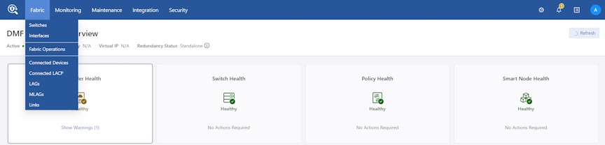
- Select the switch name to be configured with dual management.
Figure 62. Controller GUI Showing Inventory of Switches 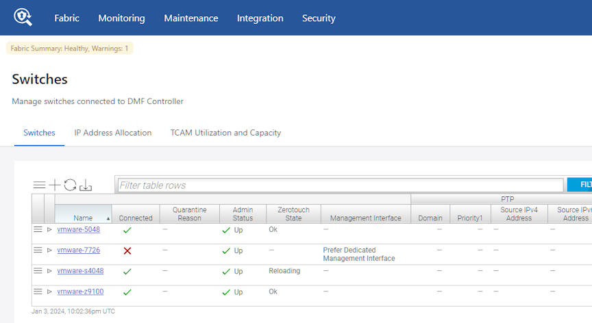
- Select the Interfaces tab.
Figure 63. Controller GUI Showing Switch Interfaces 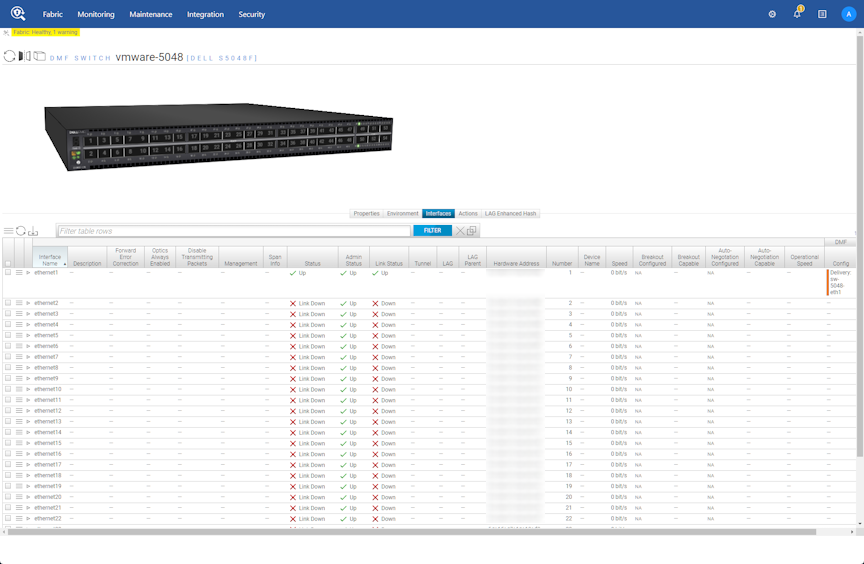
- Identify the interface to be configured as the standby management interface.
Figure 64. Controller GUI Showing Configure Knob 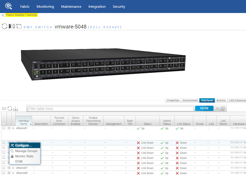
- Select Menu to the left of the identified interface, then select Configure.
Figure 65. Controller GUI Showing Interface Settings 
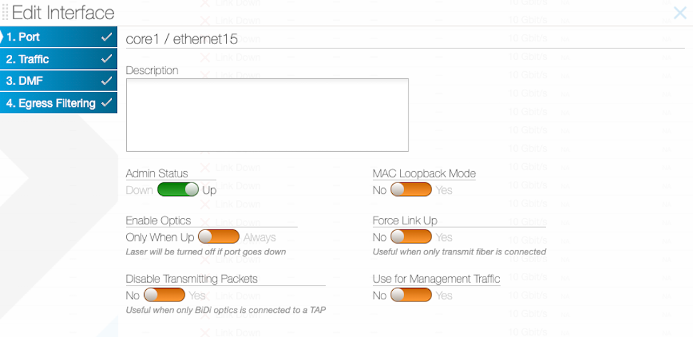
- Set Use for Management Traffic to Yes. This action configures the interface to the standby management role.
Figure 66. Use for Management Traffic 
Management Interface Selection Using the GUI
- When the dedicated management interface fails, the front panel data port becomes active as the management port.
- When the dedicated management interface returns, it becomes the active management port.
- When the management network is undependable, this can lead to switch disconnects.
The Management Interface choice dictates what happens when the management interface returns after a failover. Make this selection using the GUI or the CLI.
Select Configure Switch and choose the required Management Interface setting.
If you select Prefer Dedicated Management Interface (the default), when the dedicated management interface goes down, the front panel data port becomes the active management port for the switch. When the dedicated management port comes back up, the dedicated management port becomes the active management port again, putting the front panel data port in an admin down state.
If you select Prefer Current Interface, when the dedicated management interface goes down, the front panel data port still becomes the active management port for the switch. However, when the dedicated management port comes back up, the front panel data port continues to be the active management port.
Management Interface Selection Using the CLI
- When the dedicated management interface fails, the front panel data port becomes active as the management port.
- When the dedicated management interface returns, it becomes the active management port.
When the management network is undependable, this can lead to switch disconnects. The management interface selection choice dictates what happens when the management interface returns after a failover.
Controller-1(config)# switch DMF-SWITCH-1 Controller-1(config-switch)#management-interface-selection ? prefer-current-interface Set management interface selection algorithm prefer-dedicated-management-interface Set management interface selection algorithm (default selection) Controller-1(config-switch)#
If you select prefer-dedicated-management-interface (the default), when the dedicated management interface goes down, the front panel data port becomes the active management port for the switch. When the dedicated management port comes back up, the dedicated management port becomes the active management port again, putting the front panel data port in an admin down state.
If you select prefer-current-interface, when the dedicated management interface goes down, the front panel data port still becomes the active management port for the switch. However, when the dedicated management port comes back up, the front panel data port continues to be the active management port.
Switch Fabric Management Redundancy Status
To check the status of all switches configured with dual management as well as the interface that is being actively used for management, enter the following command in the CLI:
Controller-1# show switch all mgmt-stats
Additional Notes
- A maximum of one data-plane interface on a switch can be configured as a standby management interface.
- The switch management interface
ma1is a bond interface, havingoma1as the primary link and the data plane interface as the secondary link. - The bandwidth of the data-plane interface is limited regardless of the physical speed of the interface. Arista Networks recommends immediate remediation when the
oma1link fails.
Management Redundancy on EOS Fixed System Chassis
DANZ Monitoring Fabric (DMF) provides support for Management Redundancy on an Extensible Operating System (EOS) Fixed System Chassis. It provides a method to enable redundant active/active connectivity on the management IP address for a DMF switch in a fixed system chassis using an out-of-band management port and a front-panel port on the switch.
The feature utilizes first hop redundancy protocols such as Virtual Router Redundancy Protocol (VRRP) running in the gateway devices and addressless forwarding on the switch.
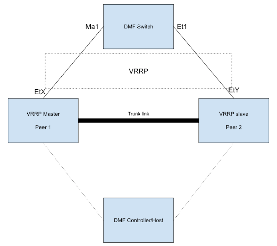
After enabling the feature, a floating loopback interface is created on the DMF switch and assigned with the Ma1 (Management interface) IP address. Addressless forwarding is enabled on Ma1 and the redundant port (e.g., Et1) along with proxy ARP. This supports the feature without using any more IP addresses. A default route is programmed on the DMF switch to point to the gateway IP (which is assumed to be the virtual IP address of the first-hop redundancy protocol).
When the feature is disabled, the system deletes the floating loopback interface on the DMF switch, and the original Ma1 configurations are automatically re-configured for the Ma1 interface.
Management Redundancy on an EOS fixed system chassis is supported on the following platforms:
- DCS-7280R/R2/R3
- DCS-7050PX4-32S
- DCS-7050DX4-32S
Configure the feature using one of the following:
Configuring Management Redundancy using the CLI
To configure the redundant management interface on the fixed system EOS switch, enter the following commands:
c1(config)# switch fixed-eos
c1(config-switch)# interface Ethernet1
c1(config-switch-if)# management
Configuring Management Redundancy using the GUI
Navigate to and select Configure using the menu icon.
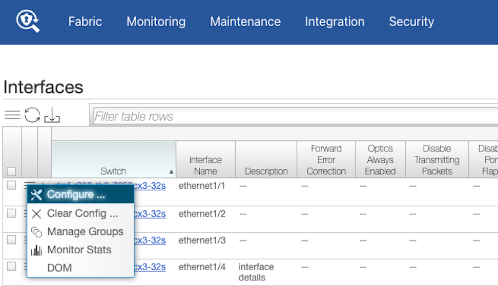
Navigate to .
Set Use for Management Traffic to Yes.
Select Save.
Show Commands
Several show commands are available to view the configuration settings of a redundant management interface.
-
Use the
show running-config switch
switch-name
command to view the running-config and the management traffic interface settings, as shown in the following example:c1(config)# show running-config switch fixed-eos ! switch switch fixed-eos mac 28:99:3a:34:42:81 ! interface Ethernet1 management -
Use the
show switch switch-name
running-config
command to view therunning-configgenerated for the switch, as shown in the following example:c1(config)# show switch fixed-eos running-config ! management dmf controller address 10.243.255.239 no disabled hostname fixed-eos username controller privilege 15 role network-admin secret sha512 $6$XTUb68lm$0ohxyre2dzkRoB9ycR37Tjy/sA/DR8V3fOpwdFSjcjy2FmB3GIyOX2T5q.JztN9/tz7ZW2VUSCyPTg8I5dDtR1 aaa authorization exec default local username admin ssh-key ssh-rsa AAAAB3NzaC1yc2EAAAADAQABAAACAQC6Bll8rjahrn2YTQ9sQbuQXkt9+KMxJWIq3+d2M6+ZGLeQ5nEMdaALQ2pSoO2DqOBvHD0zq 7qBVDzOKAEkUxdVeFuSZVcuTss32NGKU+q2oD/5Gxu+4tOWIo7J6ljWEtF6FqzINRf7mlEFpSBShLBiX5CfDCvHhwfI4fEwNGDsWS UgN19j/uWwugv3nuPulCt+2xIUPhRhKHcck6qN+1LTJFJ1VQrljqYq65lDIJ3PxgN9ML1+imbnx4w4kgUXEWRNERkZvqS7nhV1U9d vblq824eBaM3KnsgDxYDEHu3PAJZLjerqu426v/mC3J/+2ghbcfADwSww0/4rYaKS1Btt4SWG+qVDwtQSKPF9HGVz1+qlhnmGJ+02 WfqXc+qNF5Sa9RpJIJ68VMjHGIHRhOGy6CpI8kA1de2RI7xz7lgB1/3M7DYd5mdV7jlR/Bga9jWwAR60hTlzUYJrBQFJ30DIjvyT3 ZNzgmgS3Bi/fytRRYz4DjkrBNMMggXnk0kIZALxnaabPK14esInW5HMJEapMVgLraOwgGlq+8M8BfCSXbvZvAEFSNKhAE4hhoTjQ0 ds5AuVx8KZODZRnlwtzLRwIv12SCVEhT/hQufM4LDI+Aeek1WNzETAKRlZ/As21ni4+RaKGgFtfpkIp/dyviYTVinNm154SLtHzjh XeIp6rQ== floodlight@controller\n clock timezone UTC ntp server 10.243.255.239 ntp server ntp1.aristanetworks.com ntp server ntp2.aristanetworks.com ntp server ntp3.aristanetworks.com ntp server ntp4.aristanetworks.com logging host 10.243.255.239 logging host docker1.eng.bigswitch.com 11514 logging trap snmp-server engineID local 800092a20328993a344281 ! redundant management interface Ethernet1
In the example, the output shows
! redundant management interface
Ethernet1
is destined for the switch. This isn't an actual configuration in the usual sense; it’s a comment (i.e. ! is at the front of the string). This line is parsed on the EOS switch and replaced with the relevant configuration to tune the redundant management interface. - If the line
! redundant management interface
Ethernet1
is not present in the running-config of the switch, use theshow fabric warningscommand to see if there was an issue in applying the configuration to that switch interface. The following example displays the output of theshow fabric warningscommand when the switch is a VM. DMF does not support this feature for EOS VMs.c1(config)# show fabric warnings # Name Warning -|-----|---------------------------------------------------------------------------| 1 core2 Redundant management interface config not supported on VM based EOS systems
-
To confirm that management interface redundancy has been configured on EOS, use the
show switch all mgmt-statscommand. This will display the management redundancy operational-state and the interface names that are involved.c1# show switch all mgmt-stats ~~~~~~~~~~~~~~ Switches ~~~~~~~~~~~~~~ # Switch DPID Redundant -|-------------------------|---------| 1 swl False 2 eos True ~~~~~~~~~~~~~~~~~~ Interfaces of Switch DPIDs ~~~~~~~~~~~~~~~~~~ # Switch DPID Interface Active Fail Count LinkUp -|-------------------------|-----------|------|----------|------| 1 swl ethernet2 False 1 False 2 swl oma1 True 0 True 3 eos Ethernet9 True 3 True 4 eos Management1 True 8 True
- In the earlier example, the switch eos shows the operational state of management redundancy. The redundant interfaces are Ethernet9 and Management1.
Troubleshooting
Limitations
- The
Management1interface should be active during the switch reboot and image upgrade. - A default gateway is configured on the switch when the feature is enabled.
- The feature doesn’t work with DHCP configuration on the Management interface.
- The feature only works for fixed system chassis.
- Port configurations such as VLAN tagging, stripping VLAN, rate limit, disabling transmission, and setting truncation size are not allowed for the port chosen as a redundant interface.
- The switch's Management interface can only be configured with CLI commands that are also supported for the loopback interface.
- A LAG/Port-Channel cannot be configured as a redundant management port.
- The front-panel redundant port can have a different MTU value than the Management interface.
- In earlier releases, the CLI command
show switch all mgmt-statswill not display the correct interface redundancy opstate.
Controller Lockdown
Controller lockdown mode, when enabled, disallows user configuration such as policy configuration, inline configuration, and rebooting of fabric components and disables data path event processing. If there is any change in the data path, it will not be processed.
The primary use case for this feature is a planned management switch upgrade. During a planned management switch upgrade, DANZ Monitoring Fabric (DMF) switches disconnect from the Controller, and DMF policies are reprogrammed, disrupting traffic forwarding to tools. Enabling this feature before starting a management switch upgrade will not disrupt the existing DMF policies when DMF switches disconnect from the Controller, thereby forwarding traffic to the tools.
- Operations such as switch reboot, Controller reboot, Controller failover, Controller upgrade, policy configuration, etc., are disabled when Controller lockdown mode is enabled.
- The command to enable Controller lockdown mode, system control-plane-lockdown enable, is not saved to the running config. Hence, Controller lockdown mode is disabled after Controller power down/up. When failover happens with a redundant Controller configured, the new active Controller will be in Controller lockdown mode but may not have all policy information.
- In Controller lockdown mode, copying the running config to a snapshot will not include the system control-plane-lockdown enable command.
- The CLI prompt will start with the prefix
LOCKDOWNwhen this feature is enabled. - Link up/down and other events during Controller lockdown mode are processed after Controller lockdown mode is disabled.
- All the events handled by the switch are processed in Controller lockdown mode. For example, traffic is hashed to other members automatically in Controller lockdown mode if one LAG member fails. Likewise, all switch-handled events related to inline are processed in Controller lockdown mode.
Controller# configure
Controller(config)# system control-plane-lockdown enable
Enabling control-plane-lockdown may cause service interruption. Do you want to continue ("y" or "yes
" to continue):yes
LOCKDOWN Controller(config)#
LOCKDOWN Controller(config)# system control-plane-lockdown disable
Disabling control-plane-lockdown will bring the fabric to normal operation. This may cause some
service interruption during the transition. Do you want to continue ("y" or "yes" to continue):
yes
Controller(config)#
CPU Queue Stats and Debug Counters
Switch Light OS (SWL) switches can now report their CPU queue statistics and debug counters. To view these statistics, use the DANZ Monitoring Fabric (DMF) Controller CLI. DMF exports the statistics to any connected DMF Analytics Node.
The CPU queue statistics provide visibility into the different queues that the switch uses to prioritize packets needing to be processed by the CPU. Higher-priority traffic is assigned to higher-priority queues.
The SWL debug counters, while not strictly limited to packet processing, include information related to the Packet-In Multiplexing Unit (PIMU). The PIMU performs software-based rate limiting and acts as a second layer of protection for the CPU, allowing the switch to prioritize specific traffic.
Configuration
These statistics are collected automatically and do not require any additional configuration to enable.
To export statistics, configure a DMF Analytics Node. Please refer to the DMF User Guide for help configuring an Analytics Node.
Show Commands
Showing the CPU Queue Statistics
controller-1> show switch FILTER-SWITCH-1 queue cpu
# Switch            OF Port Queue ID Type      Tx Packets Tx Bytes  Tx Drops Usage
-|-----------------|-------|--------|---------|----------|---------|--------|---------------------------------|
1 FILTER-SWITCH-1   local   0        multicast 830886     164100990 0        lldp, l3-delivery-arp, tunnel-arp
2 FILTER-SWITCH-1   local   1        multicast 0          0         0        l3-filter-arp, analytics
3 FILTER-SWITCH-1   local   2        multicast 0          0         0
4 FILTER-SWITCH-1   local   3        multicast 0          0         0
5 FILTER-SWITCH-1   local   4        multicast 0          0         0        sflow
6 FILTER-SWITCH-1   local   5        multicast 0          0         0
7 FILTER-SWITCH-1   local   6        multicast 0          0         0        l3-filter-icmp
There are a few things to note about this output:
- The CPU's logical port is also known as the local port.
- The counter values shown are based on the last time the statistics were cleared.
- Different CPU queues may be used for various types of traffic. The Usage column displays the traffic that an individual queue is handling. Not every CPU queue is used.
The details token can be added to view more information. This includes the absolute (or raw) counter values, the last updated time, and the last cleared time.
Showing the Debug Counters
controller-1> show switch FILTER-SWITCH-1 debug-counters
#  Switch            Name                            Value   Description
--|-----------------|-------------------------------|-------|-------------------------------------------|
1  FILTER-SWITCH-1   arpra.total_in_packets          1183182 Packet-ins recv'd by arpra
2  FILTER-SWITCH-1   debug_counter.register          79      Number of calls to debug_counter_register
3  FILTER-SWITCH-1   debug_counter.unregister        21      Number of calls to debug_counter_unregister
4  FILTER-SWITCH-1   pdua.total_pkt_in_cnt           1183182 Packet-ins recv'd by pdua
5  FILTER-SWITCH-1   pimu.hi.drop                    8       Packets dropped
6  FILTER-SWITCH-1   pimu.hi.forward                 1183182 Packets forwarded
7  FILTER-SWITCH-1   pimu.hi.invoke                  1183190 Rate limiter invoked
8  FILTER-SWITCH-1   sflowa.counter_request          9325983 Counter requests polled by sflowa
9  FILTER-SWITCH-1   sflowa.packet_out               7883772 Sflow datagrams sent by sflowa
10 FILTER-SWITCH-1   sflowa.port_features_update     22      Port features updated by sflowa
11 FILTER-SWITCH-1   sflowa.port_status_notification 428     Port status notif's recv'd by sflowa
The counter values shown are based on the last time the statistics were cleared.
Add the name or the ID token and a debug counter name or ID to filter the output.
Add the details token to view more information. This includes the debug counter ID, the absolute (or raw) counter values, the last updated time, and the last cleared time.
Clear Commands
Clearing the Debug Counters
controller-1# clear statistics debug-counters
Clearing all Statistics
controller-1# clear statistics
Analytics Export
The following statistics are automatically exported to a connected Analytics Node:
- CPU queue statistics for every switch.
Note: This does not include the statistics for queues associated with physical switch interfaces.
- The PIMU-related debug counters. These are debug counters whose name begins with pimu. No other debug counters are exported.
DMF exports these statistics once every minute.
Troubleshooting
Use the details with the new show commands to provide more information about the statistics. This information includes timestamps showing statistics collection time and the last time the statistics were cleared.
Use the redis-cli command to query the Redis server on the Analytics Node from the Bash shell on the DMF Controller to view the statistics successfully exported to the Analytics Node.
redis-cli -h analytics-ip -p 6379 LRANGE switch-debug-counters -10 -1
redis-cli -h analytics-ip -p 6379 LRANGE switch-queue-stats -10 -1
Limitations
- Only the CPU queue stats are exported to the Analytics Node. Physical interface queue stats are not exported.
- Only the PIMU-related debug counters are exported to the Analytics Node. No other debug counters are exported.
- Only SWL switches are currently supported. EOS switches are not supported.
Egress Filtering
Egress Filtering is an option to send different traffic to each tool attached to the policy's delivery setting. It provides additional filtering at the delivery ports based on the egress filtering rules specified at the interface.
DANZ Monitoring Fabric (DMF) supports egress filtering on the delivery and recorder node interfaces and supports configuring IPv4 and IPv6 rules on the same interface. Only packets with an IPv4 header are subject to the rules associated with the IPv4 token, while packets with an IPv6 header are only subject to the rules associated with the IPv6 token. If any egress filtering rules are configured on the interface, a default drop rule is applied if no traffic matches the configured rules.
Egress Filtering applies to all switches running SWL OS and EOS DCS-7280R/R2/R3 switches.
Configuring Egress Filtering using the CLI
CLI Configuration
egress-filtering command from the config-switch-if submode.
dmf-controller(config)# switch DCS-7050SX3-48YC8
dmf-controller(config-switch)# interface ethernet18
dmf-controller(config-switch-if)# egress-filtering
dmf-controller(config-switch-if-egress-filtering)#
In the config-switch-if-egress-filtering submode, enter the rule's sequence number. The number represents the sequence in which the rules are applied. The lowest sequence number will have the highest priority.
dmf-controller(config-switch-if-egress-filtering)# 1
allow     Forward traffic matching this rule
drop      Drop traffic matching this rule
drop orallow.
dmf-controller(config-switch-if-egress-filtering)# 1 allow
any ipv4 ipv6
IPv4, IPv6, or any.
dmf-controller(config-switch-if-egress-filtering)# 1 allow
any   ipv4  ipv6
Any Traffic
ethernet18.
dmf-controller(config-switch-if-egress-filtering)# 1 allow any
ethernet18.
dmf-controller(config-switch-if-egress-filtering)# 1 drop any
IPv4 Traffic
To allow or drop all IPv4 traffic on an interface, use the following commands:
dmf-controller(config-switch-if-egress-filtering)# 1 drop ipv4
dmf-controller(config-switch-if-egress-filtering-ipv4)#
dmf-controller(config-switch-if-egress-filtering)# 1 allow ipv4
dmf-controller(config-switch-if-egress-filtering-ipv4)#
The following other options are available in the submode
config-switch-if-egress-filtering-ipv4. DMF supports the following qualifiers for IPv4 traffic filtering along with the IP address, port, and VLAN ranges.
dmf-controller(config-switch-if-egress-filtering-ipv4)#
dscp-value      dst-port        icmp-code       ip-proto        src-port        vlan-range
dst-ip          dst-port-range  icmp-type       src-ip          src-port-range
dst-ip-range    ecn-value       ip-fragment     src-ip-range    vlan
The following are examples of using the different options.
dmf-controller(config-switch-if-egress-filtering-ipv4)# dst-ip 12.123.123.39
dmf-controller(config-switch-if-egress-filtering-ipv4)# ip-proto 6
dmf-controller(config-switch-if-egress-filtering-ipv4)# dst-port 13
dmf-controller(config-switch-if-egress-filtering-ipv4)# src-port-range min 12 max 23
dmf-controller(config-switch-if-egress-filtering-ipv4)# vlan 45
dmf-controller(config-switch-if-egress-filtering-ipv4)# src-ip 12.123.145.39
dmf-controller(config-switch-if-egress-filtering-ipv4)# dscp-value 23
dmf-controller(config-switch-if-egress-filtering-ipv4)# icmp-type 34
dmf-controller(config-switch-if-egress-filtering-ipv4)# icmp-code 59
dmf-controller(config-switch-if-egress-filtering-ipv4)# ecn-value 2
dmf-controller(config-switch-if-egress-filtering-ipv4)# ip-fragment is-fragment
IPv6 Traffic
To allow or drop all IPv6 traffic on an interface, use the following commands:
dmf-controller(config-switch-if-egress-filtering)# 1 drop ipv6
dmf-controller(config-switch-if-egress-filtering-ipv6)#
dmf-controller(config-switch-if-egress-filtering)# 1 allow ipv6
dmf-controller(config-switch-if-egress-filtering-ipv6)#
config-switch-if-egress-filtering-ipv6 for IPv6 traffic filtering.
dmf-controller(config-switch-if-egress-filtering-ipv6)#
dscp-value      dst-port        icmp-code       ip-proto        src-port        vlan-range
dst-ip          dst-port-range  icmp-type       src-ip          src-port-range
dst-ip-range    ecn-value       ip-fragment     src-ip-range    vlan
Configuring an unsupported qualifier on a switch interface results in the following error message:
dmf-controller(config)# show fabric warnings egress-filtering-warning
~~~~~~~~~~~~~~~~~~~~~~~~~ Egress filtering warnings ~~~~~~~~~~~~~~~~~~~~~~~~~
# Switch         IF Name      Warning message
-|--------------|------------|------------------------------------------------------------------------------------------|
1 DCS-7050SX3    ethernet18   Rule 1 matching on the following field(s) is not supported on the switch: ECN; IP fragment
Show Commands
dmf-controller# show switch all table egress-flow-1
# Egress-flow-1 Device name        Entry key                                                       Entry value
-|-------------|------------------|---------------------------------------------------------------|----------------------------------------------|
1 0             DCS-7050SX3-48YC8  Priority(1000), Port(13), EthType(2048), Ipv4Src(12.123.123.12) Name(__Rule1__), Data([0, 0, 0, 0]), NoDrop()
2 1             DCS-7050SX3-48YC8  Priority(0), Port(13)                                           Name(__Rule0__), Data([0, 0, 0, 0]), Drop()
If any egress filtering warnings are present, they can be seen by running the show fabric warnings egress-filtering-warnings command. The output lists the switch name and the interface name on which an egress filtering warning is present, with a detailed message.
Validation Messages
The following are examples of validation failure messages and their potential causes.
EtherType.
Validation failed: EtherType is mandatory for egress filtering rule
Validation failed: A rule cannot contain more than 2 configured ranges
Validation failed: Source port and its ranges are not supported together
Validation failed: Inner VLAN min cannot be greater than inner VLAN max
ip-proto setting is mandatory when specifying any port number, source, or destination. Specifying the source or destination port without ip-proto causes a validation failure.
Validation failed: IP protocol number is mandatory for source port
Validation failed: IP protocol number is mandatory for destination port
ip-proto. DMF only supports TCP(6), UDP(17), and SCTP(132) protocol numbers for port qualifiers.
Validation failed: IP protocol number protocol number is unsupported for source port
Validation failed: IP protocol number protocol number is unsupported for destination port
Configuring Egress Filtering using the GUI
- Navigate to .
Figure 75. DMF Interfaces 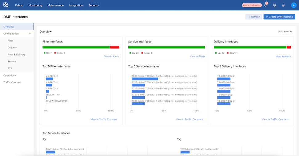
- Under the Configuration tab select either Delivery or Filter & Delivery.
Note: DMF supports configuring egress filtering rules for Delivery, Filter & Delivery, and Recorder Node interfaces.
Figure 76. Delivery Interfaces 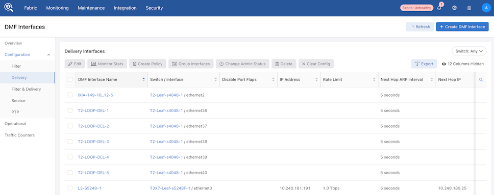
- Optional - If required, create a Delivery or Filter & Delivery interface using Create DMF Interface.
Figure 77. Create DMF Interface 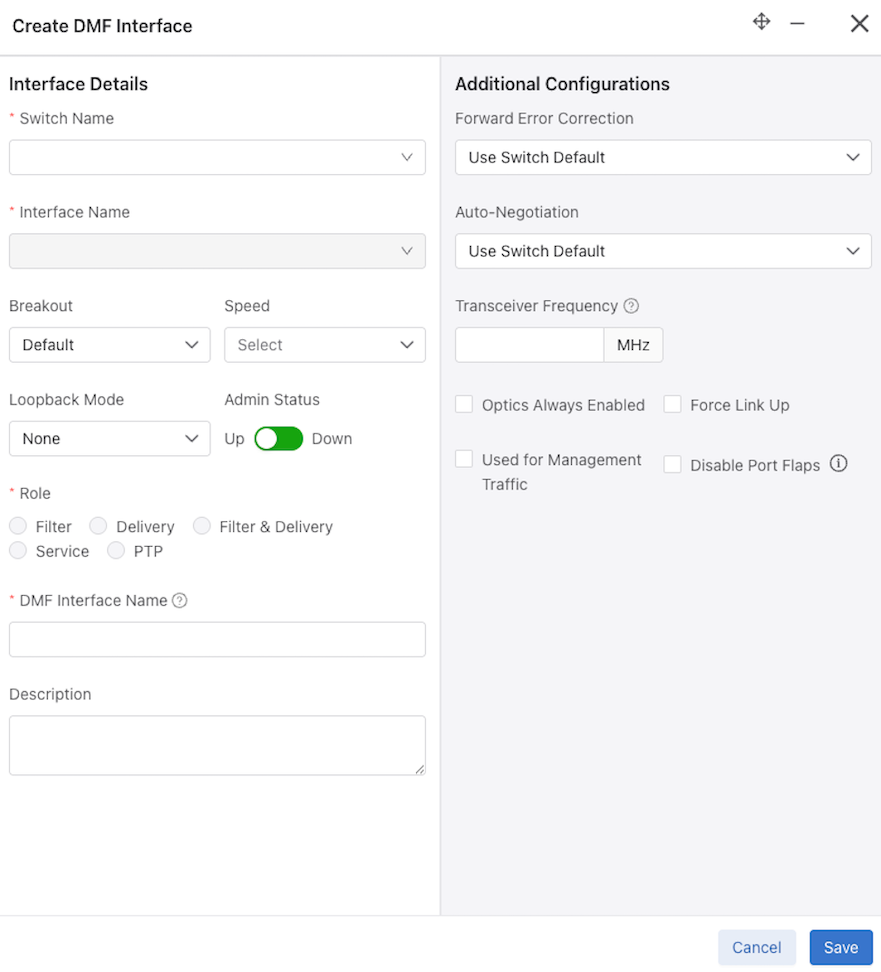
- Under the DMF Interface Name, select the Delivery or Filter & Delivery interface to configure additional interface attributes.
Figure 78. DMF Interface Details 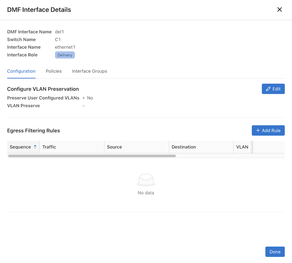
- Under Configuration, select + Add Rule in the Egress Filtering Rules section.
Figure 79. Add New Rule 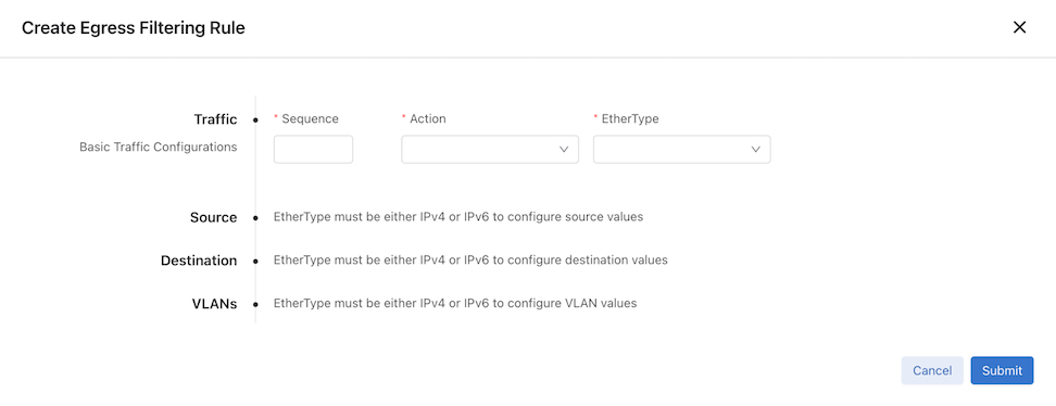
- Setting EtherType to either IPv4 or IPv6 displays additional configuration options.
- Traffic: Basic traffic configurations.
- Sequence - Enter a numerical value. The lowest sequence number will have the highest priority.
- Action (drop-down) - Allow or Drop
- Ethertype (drop-down) - IPv4, IPv6, or Any
- Source: Single IP or IP Range.
- IP Address
- IP Mask
- Destination: Single IP or IP Range.
- IP Address
- IP Mask
- VLANs: VLAN (drop-down) - Any, Single, or Range.
Figure 80. EtherType Settings 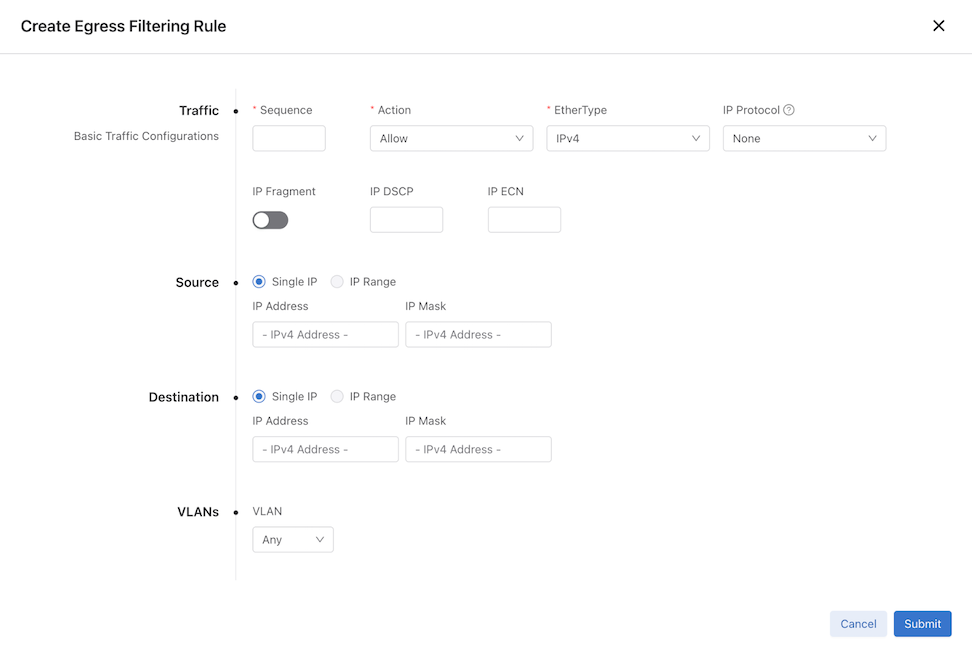
- Traffic: Basic traffic configurations.
- Repeat the process using + Add Rule to add more rules as needed.
Figure 81. Edit Interface 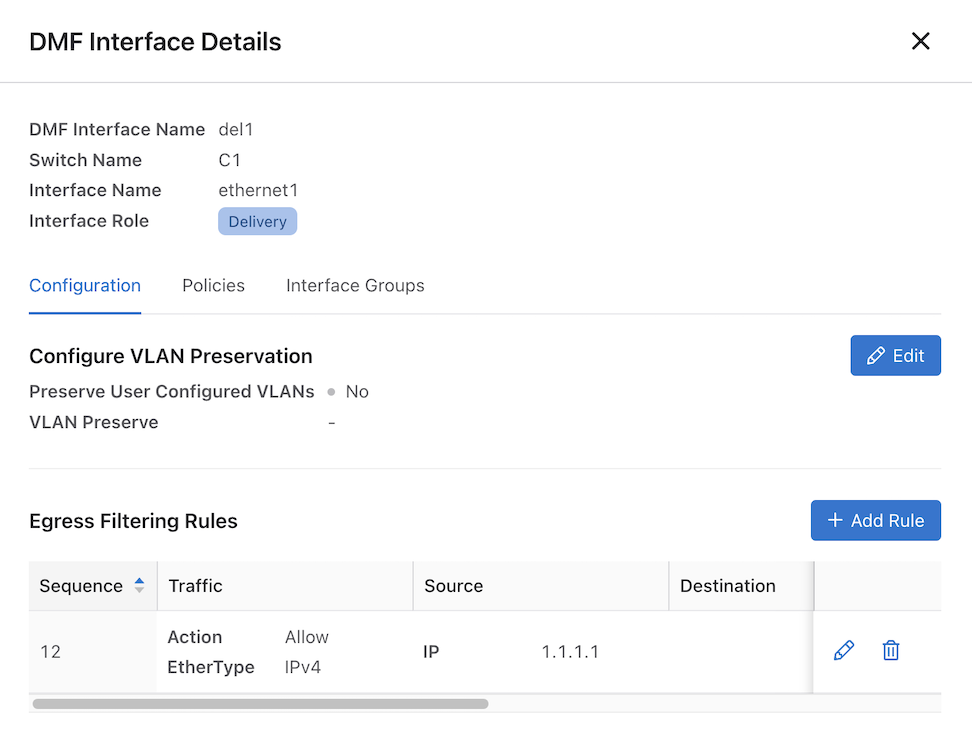
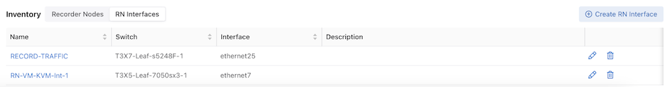
Syslog Messages
There are no Syslog messages relevant to the Egress Filtering feature.
Troubleshooting
Limitations
- Egress filtering supports only 500 rules per interface. A validation failure occurs when exceeding this limit.
Validation failed: Only 500 egress filtering rules are supported per interface
- DMF does not support egress filtering on MLAG delivery interfaces.
- EOS DCS-7280R/R2/R3 switches do not support
VLANqualifiers and their ranges. - SWL OS switches do not support the following qualifiers:
icmp-code,icmp-type,ecn-value,dscp-value, andip-fragment. - For EOS 7280R3,
dst-portonly works on VLAN-tagged packets when there is an exact match. - None of the IPv6 qualifiers work for EOS 7280R and 7280R2 switches.
- SWL OS switches do not support the following qualifiers under
IPv6submode:src-ip,dst-ip,src-ip-range, anddst-ip-range.