Maintenance and Field Replacement

This appendix describes the process for replacing switch components.

You must ensure that at least one of the secondary grounding pads located on the front panel of the chassis is connected to the data center ground. While working on the switches, use grounded, anti-static wrist straps connected to one of the attach points on the switch for grounding yourself and preventing ESD damage to the switch.


Note: Illustrations in this appendix are examples for a representative switch and component(s). Procedures must be applied to component(s) supported by the specific device. You must use component(s) and the appropriate slots for those component(s) when replacing or adding them.


Power Supplies

The switches support AC or DC Power supplies. The switches ship with a number of populated slots depending on the switch model. Empty slots are covered with a blank. For adding a new power supply in one of the available slots, remove the blank covering the slot before inserting a new power supply.The following steps are required for ESD protection when adding or replacing power supplies.


Note: For the exact locations of power supplies for your device, refer to Rear Panel.


  1. Ensure that the switch is grounded.
    1. Connect at least one of the secondary grounding pads located on the front panel of the chassis to the data center ground as needed.
  2. Ground yourself using a connected, anti-static wrist strap.
    1. The anti-static ESD wrist strap must be connected to one of the attach points on the switch.
  3. Remove the power supply to be replaced (Removing AC Power Supply, Removing DC Power Supply) or the blank for the slot (Removing Fabric Module Blank) in which the new power supply is to be added.

Removing Power Supply Blank

The power supply blank is screwed on. Use the appropriate screwdriver for your switch.
  1. Put on a grounded, anti-static ESD strap.
  2. Unscrew the blank from the power supply slot you are going to populate.

    You may want to save the blank for future use as needed. The blank is needed for the switch to operate normally if a power supply slot is not populated.

Removing AC Power Supply

Perform the following steps to remove an AC power supply.
  1. Put on a grounded, anti-static ESD strap.
  2. Lift the retaining clip up and unplug the cable (if present).
    Figure 1. Unseat Power Supply
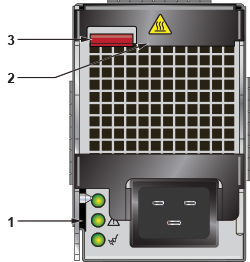
    1 Status LED 3 Ejector button
    2 Release lever    
  3. Pull the ejectors forward until the power supply disconnects.
  4. Remove the power supply from the Switch using the power supply lever and handle.

Installing AC Power Supply

You must make space for installing the power supply by removing an existing one (Removing AC Power Supply, Removing DC Power Supply) or removing a blank (Removing Power Supply Blank) from a power supply slot available on the switch.

Perform the following steps to install an AC power supply.

  1. Put on a grounded, anti-static ESD strap.
  2. Unpack the new power supply.
  3. Insert the new power supply into the empty power supply slot.
  4. After you insert the power supply, push gently on the power supply until the power supply is fully seated.
  5. Pull up on the handle on the power supply to lock the power supply in place.
  6. Connect the power cord to the power supply.
  7. Fasten the spring-release clip to the power cord.
  8. Connect to the power source.
  9. Verify normal operation using the LED indicators for your switch Power Supply Status Indicators.

Removing DC Power Supply

Before performing any of the steps, ensure power is removed from DC circuits by turning off the power line servicing the circuits.

Make sure to remove the ground connection last when removing power.

  1. Put on a grounded, anti-static ESD strap.
  2. Disconnect the power cable from the DC power source.
  3. Loosen the two captive screws on the bottom of the adapter from the power supply module.
  4. Slide the cover out from the terminal studs.
  5. Remove each power cable lug to the terminal studs with the flange locking nuts.
  6. Remove the flange locking nuts to each of the terminal studs.
  7. Remove the clear plastic cover protecting the terminal studs on the adapter. Slide the cover off of the adapter.
  8. Disconnect the power cable lug from the terminal studs.

Installing DC Power Supply

You must make space for installing the power supply by removing an existing one (Removing AC Power Supply, Removing DC Power Supply) or removing a blank (Removing Power Supply Blank) from a power supply slot available on the switch.

Perform the following steps to install a DC power supply.

  1. Put on a grounded ESD strap.
  2. Unbox the new power supply.
  3. Insert the new power supply into the empty power supply slot.
  4. After you insert the power supply, push gently on the power supply until the power supply is fully seated.
  5. Pull up on the handle on the power supply to lock the power supply in place.
  6. Connect the cables for your power supply as explained in the guide (Cabling the DC Power Supply).

Fabric and Fan Module (Fabric Module)

Note: For NEBS-compliant Service Provider installations, refer to Removing Service Provider 7500N Series Fan and Safety Guard. Contact your Arista representative if needed.

The fabric and fan modules are hot-swappable. They are accessible from the rear of the switch (Rear Panel). You must take into account that the module you are inserting is compatible with the switch and the module that you are replacing. Perform the following steps to remove and replace a fabric and fan module, or a fan-only module, if your switch supports one.

Removing Fabric Module Blank

The fabric module blank is screwed on. Use the appropriate screwdriver for your switch.
  1. Put on a grounded, anti-static ESD strap.
  2. Unscrew the blank from the fabric module slot you are going to populate.

    You may want to save the blank for future use as needed. The blank is needed for the switch to operate normally if a fabric module slot is not populated.

Removing Fabric Module

  1. Put on a grounded, anti-static ESD strap.
  2. Loosen the two Phillips screws on the fabric module.
  3. Pull out the ejector handle on the fabric module.
  4. Pull the ejector handles outwards by 90 degrees to disengage the fabric module.
  5. Pull on the ejector handles to remove the fabric module from the slot.
    Note: Fabric modules can be heavier than 25 lbs. Provide adequate support while handling them to prevent injury or damage.

Installing Fabric Module

You must make space for installing the module by removing an existing one (Removing Fabric Module) or removing a blank (Removing Fabric Module Blank) from a fabric module slot available on the switch.

Perform the following steps to install the module.

  1. Put on a grounded, anti-static ESD strap.
  2. Unpack the module to be installed.
  3. Open the ejector handles and carefully slide the module into the open slot.
  4. Seat the module with the ejector handles open at 90 degrees.
  5. Close the ejector handles.
  6. Screw in the two Phillips screws.
  7. Verify that the module is operating normally (Power Supply Status Indicators).
  8. Use the show environment cooling command to further verify normal operation.

Removing Service Provider 7500N Series Fan and Safety Guard

ESD GROUNDING STRAP ADDITION

This product must be grounded. Never defeat the ground conductor or operate the equipment in the absence of a suitably installed ground conductor. Contact the appropriate electrical inspection authority or an electrician if you are uncertain that suitable grounding is available. When installing or replacing this product, the ground connection must always be made first and disconnected last, and the person performing the task(s) must wear a grounded, ESD (anti-static) strap.

On 7500 series products, you must replace the entire fabric module to replace a fan.
  • For the 7504 and 7508, unscrew the two Phillips screws on the back of the fabric module. Rotate the ejector handle(s) 90 degrees back to hard stops and pull the fabric module straight back to remove. Install the replacement fabric module by first opening the ejector handle(s), then aligning the module in its slot with the same orientation as the original, and sliding it into the slot in the same orientation as the one removed. When the module is seated, rotate the ejector handle(s) forward and fasten the Phillips screws.Do not overtighten Phillips screws.
  • For the 7512 the failed fan replacement requires the removal of the plastic safety guard in addition to the fabric module. First, in the CLI console, enter the global configuration mode by issuing the commands enable, then config, followed by env fan-speed override 100 to increase fan speeds. Wait five minutes for the system to sufficiently cool. Unscrew the six captive screws on the outside perimeter of the plastic safety guard. Set the safety guard aside. Fabric module removal and reinstallation procedure is the same as the 7504/7508 instructions above. Caution, the 7512R fabric module weighs more than 25lbs. Support module during handling. Reinstall plastic safety guard and fasten the six captive screws. Issue the env fan-speed auto command in the CLI console for normal operation.

Touch Point Shield (Optional)

Installing the Touch Point Shield

The 7512N supports an optional Touch Point Shield component that is attached to the rear of the device. Perform the following steps to install the Touch Point Shield to the 7512N.
  1. Attach the ground cable to the chassis.
    Note: The ground cable should be attached so that it exits upwards to enable access to the ESD port on the chassis. You may arc the ground cable downwards, if needed (Figure 2).
  2. Match the six screws on the Touch Point Shield to the holes on the chassis and screw in the Touch Point Shield).
    Figure 2. Installing the Touch Point Shield (7512N)
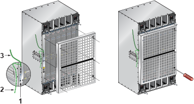
    1 ESD port 3 Ground cable going up
    2 Ground cable going down    

Supervisor Module

The supervisor modules are hot-swappable. They are accessible from the front of the switch. You must take into account that the module you are inserting is compatible with the switch and the module that you are replacing. Use the following procedure to remove and replace a supervisor module. For the supervisor module locations for your device, refer to Front Panel.

Removing Supervisor Module Blank

The fabric module blank is screwed on. Use the appropriate screwdriver for your switch.
  1. Put on a grounded, anti-static ESD strap.
  2. Unscrew the blank from the fabric module slot you are going to populate.

    You may want to save the blank for future use as needed. The blank is needed for the switch to operate normally if a fabric module slot is not populated.

Removing Supervisor Module

Perform the following steps to remove the module.
  1. Put on a grounded ESD strap.
  2. Pinch ejector buttons on handles or levers on each end of the supervisor card.
  3. Spread the ejector buttons on the handles outwards.
  4. Pull the supervisor module out by the ejector buttons on the handles of the supervisor card.
  5. Slide supervisor module out of the slot.

Installing Supervisor Module

You must make space for installing the module by removing an existing one (Removing Supervisor Module) or removing a blank (Removing Supervisor Module Blank) from a supervisor module slot available on the switch.

Perform the following steps to install the module.

  1. Put on a grounded, anti-static ESD strap.
  2. Unpack the supervisor module to be installed.
  3. Pinch ejector buttons on handles or levers on each end of the card.
  4. Slide supervisor module into slot.
  5. Spread ejector buttons on the handles.
  6. Verify that the module is operating normally (Supervisor Module).

Linecards

The linecards are hot-swappable. They are accessible from the front of the switch. You must take into account that the linecard you are inserting is compatible with the switch and the linecard that you are replacing.

Use the following procedure to remove and replace a linecard. If you are adding a new linecard, remove the blank from the linecard slot and install the new linecard. For the linecard locations on your switch, refer to Front Panel.

Removing Linecard Blank

The linecard blank is screwed on. Use the appropriate screwdriver for your switch.
  1. Put on a grounded, anti-static ESD strap.
  2. Unscrew the blank from the linecard slot you are going to populate.

    You may want to save the blank for future use as needed. The blank is needed for the switch to operate normally if a linecard slot is not populated.

Removing Linecard

Perform the following steps to remove a linecard.
  1. Put on a grounded, anti-static ESD strap.
  2. Pinch ejector buttons on handles or levers on each end of the linecard.
  3. Pull the linecard out by the ejector buttons on the handles of linecard.
  4. Slide linecard out of the slot.

Installing Linecard

You must make space for installing the linecard by removing an existing one (Removing Linecard) or removing a blank (Removing Linecard Blank) from a linecard slot available on the switch.
  1. Put on a grounded, anti-static ESD strap.
  2. Unpack the linecard to be installed.
  3. Pinch ejector buttons on handles or levers on each end of the linecard.
  4. Spread ejector buttons on the handles.
  5. Slide the linecard into the slot.
  6. Push ejector buttons on the handles of the linecard.
  7. Verify that the linecard is operating normally (Fabric Status Indicators).