Rack Mounting the Switch
- Two-Post Rack Mount provides instructions for mounting the switch in a two-post rack.
- Four-Post Rack Mount provides instructions for mounting the 7504N and 7508N switches in a four-post rack.
- 7512N and 7516N Shelf Rack Mount Installation provides instructions for mounting the 7512N and the 7516N switches in a shelf four-post rack.
The rack mounting procedure is identical for the 7504N and 7508N Series switches. Illustrations in this chapter depict the mounting of an unpopulated 8-slot chassis.
The 7512N and 7516N switches only require a different mounting shelf for the four-post rack. Illustrations in this chapter depict the mounting of an unpopulated 12-slot chassis and a 16-slot chassis.
After completing the instructions for your rack type, proceed to Cabling the Modular Switch.
7504N and 7508N Rack Mounting
Two-Post Rack Mount
To mount the switch to a two-post rack, assemble mounting brackets to the middle of the chassis, then attach the brackets to the rack. The switch does not support a front or rear mount into a two-post rack.
- 2 - center-mount brackets
- 20 - M4x8 pan-head Phillips screws
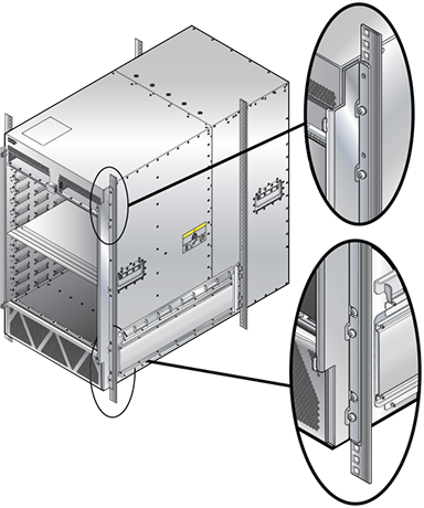
Attaching Mounting Brackets to the Chassis
- Attach both center-mount brackets to the chassis. Each bracket requires ten M4x8 pan-head Phillips screws.
Figure 1. Attaching the Center-mount Brackets 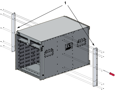
1 Center mount brackets
Inserting the Switch into the Rack (7504N)
Four-Post Rack Mount
The switch is mounted onto a four-post rack by assembling a shelf into the rack and then placing the switch on the shelf.
Illustrations in this section depict the mounting of an unpopulated 8-slot chassis.
- 2 front brackets
- 4 shelf supports
- 2 back brackets (not needed for racks with threaded holes)
- left shelf
- right shelf
The Figure 4 display the front four-post mounting parts. The Figure 5 display the rear four-post mounting parts.
Assembling the Shelf (7504N and 7508N)
- Secure the shelf support to the post with nuts that fit the screws threaded through the post.
7504N - Requires six M6 screws and cage nuts.
7508N - Requires eight M6 screws and cage nuts.
Figure 4. Left Front Post Assembly: Four-Post Rack Mount 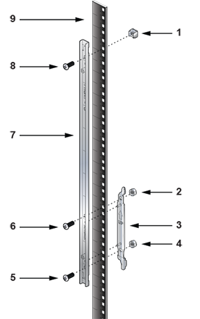
1 M6 cage nut 4 M6 nut 7 Front Bracket 2 M6 nut 5 Switch Bottom 8 M6 screw 3 Shelf support 6 Switch Top 9 Front rack post - Attach the shelf support and back bracket to the left rear post. The shelf support must be assembled on the front and rear posts at the same vertical level. An up arrow is printed on the shelf support to indicate its proper orientation.
Unthreaded rack holes: Attach the parts as displayed in following figures.
Threaded rack holes: Attach the shelf support to the post with screws that thread into the rack post. The back bracket is not required on threaded racks.
Figure 5. Left Rear Post Assembly and Shelf Support Orientation 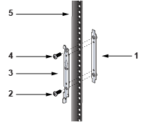
1 Back bracket 2 M6 screw 3 Shelf support 5 M6 screw 5 Rear rack post 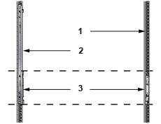
1 Rear rack post 2 Front rack post 3 Shelf supports - Install the right shelf on the right front and rear rack posts by repeating Step 5 and Step 6 to obtain the rack configuration.
Figure 6. Adjusting the Left Shelf 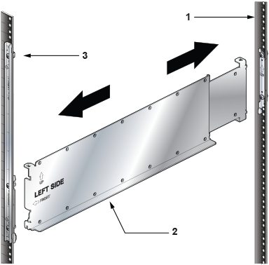
1 Rear rack post 2 Left shelf 3 Front rack post Figure 7. Both Switch Shelves Installed 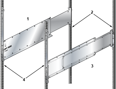
1 Left shelf 3 Right shelf 2 Rear rack post 4 Front rack post
Inserting the Switch into the Rack (7508N)
- Lift the chassis into the rack.
Figure 8. Lifting the Chassis 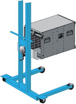
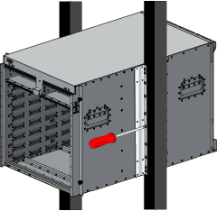
- Secure the chassis by tightening the thumbscrews on the front flanges into the rack posts, as shown in the following figure.
Figure 9. Secure the Switch to the Rack Shelf 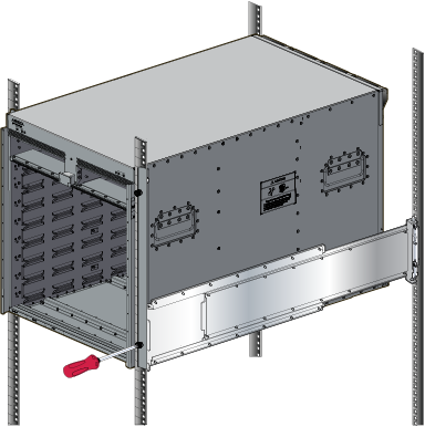
7512N and 7516N Shelf Rack Mount Installation
The following discusses the rack mounting assembly procedure for the 7512N and 7516N Series switches.
Assembling the Shelf
- Remove the plastic alignment spacers for threaded racks and select the 3 mm diameter alignment pins.
Figure 10. Alignment Spacer 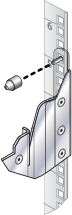
Figure 11. Rack Mount Shelf Orientation 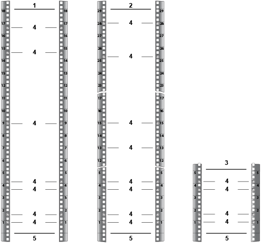
1 7512N Top (Front) 2 7516N Top (Front) 3 Rack (Rear - both switches) 4 Cage nut locations 5 Switch Bottom The following table lists the cage nut locations for the rack's front and rear switches.
Table 1. Cage Nut Locations on the Rack Switch Cage Nut Locations 7512N (Front of the rack)
Top hole 1st U Middle hole 2nd U
Middle hole 4th U
Bottom hole 5th U
Top hole 9th U
Middle hole 15th U
Middle hole 17th U
7516N (Front of the rack)
Top hole 1st U Middle hole 2nd U
Middle hole 4th U
Bottom hole 5th U
Top hole 13th U
Top hole 16th U
Bottom hole 26th U
Top hole 28th U
7512N and 7516N (Rear of the rack)
Top hole 1st U Middle hole 2nd U
Middle hole 4th U
Bottom hole 5th U
- Hook the alignment pin to the bottom hole of the 6th U from the bottom, as shown.
Figure 12. Left Front Post Assembly 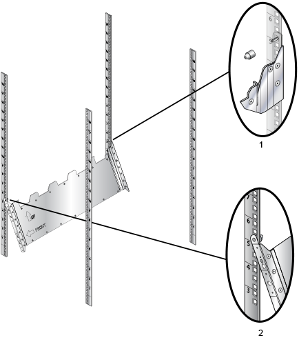
1 For the threaded rack, remove the plastic alignment spacer and use a 3 mm diameter alignment pin as shown. 2 Hook the alignment pin to the bottom hole of the 6th U from the bottom. Repeat Step 1 and Step 3 on the right front rack post, assembling the parts at the same vertical level as those on the left rack post.
- Threaded rack holes: Attach the shelf support to the post with screws that thread into the rack post.
Figure 13. Left Rear Post Assembly and Shelf Support Orientation 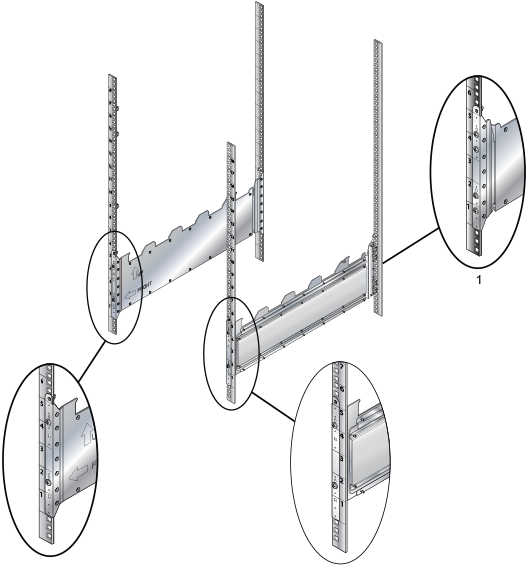
1 Install all four screws in the back. - Rear: Fasten screws to all holes
- Front: Fasten screws only where indicated with arrows (2x).
- Rear: Fasten screws to all holes.
Figure 14. Lower the Shelf into the Bracket Stubs 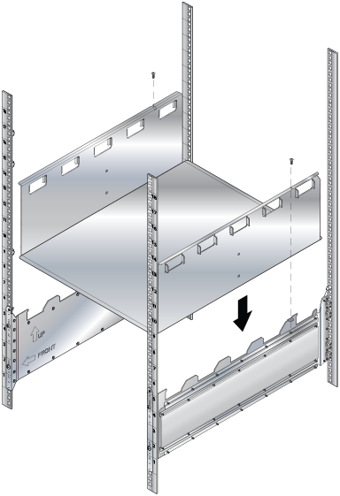
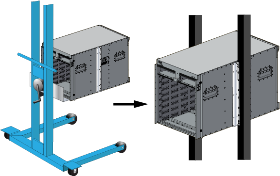
Inserting the Switch into the Rack
- Move the chassis to the rack using a mechanical lift (Figure 15 shows the 12-slot).
If modules are inserted in the chassis, use the lift carefully to avoid damaging any components.
Figure 15. Lifting the 12-slot Chassis 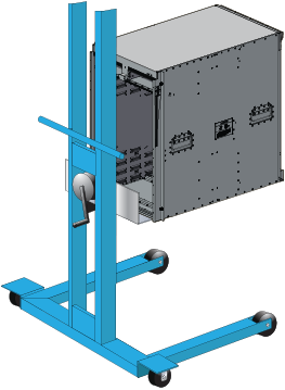
- Carefully install the switch into the rack.
Figure 16. Installing the Switch into the Rack 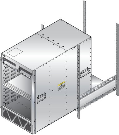
Figure 17. Secure the Chassis to the Rack