Status Indicators
This section discusses the following topics:
Supervisor Module
While the front panel of each switch can house two supervisors, switch operations require only one. Supervisors display switch component status and contain Ethernet management and console ports.
Supervisor Indicators: 7500E-SUP/7500-SUP2
- One serial console port.
- Two Ethernet management ports.
- Two USB ports.
- One clock input port.
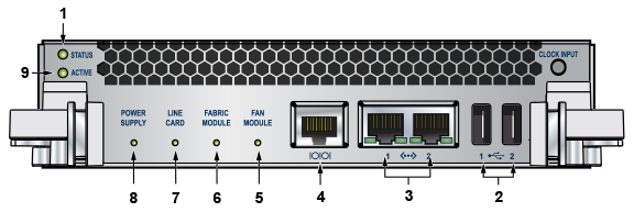
| 1 | Status LED | 2 | USB ports | 3 | Ethernet management ports |
| 4 | Serial console port | 5 | Fan module status LED | 6 | Fabric module status LED |
| 7 | Linecard status LED | 8 | Power supply status LED | 9 | Active LED |
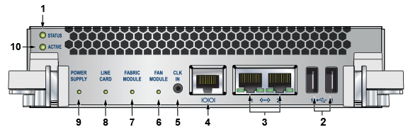
| 1 | Status LED | 2 | USB ports | 3 | Ethernet management ports |
| 4 | Serial console port | 5 | Clock input port (optional) | 6 | Fan module status LED |
| 7 | Fabric module status LED | 8 | Linecard status LED | 9 | Power supply status LED |
| 10 | Active LED |
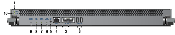
| 1 | Status LED | 2 | USB ports | 3 | Ethernet management ports |
| 4 | Serial console port | 5 | Clock input port (optional) | 6 | Fan module status LED |
| 7 | Fabric module status LED | 8 | Linecard status LED | 9 | Power supply status LED |
| 10 | Active LED |
Supervisor Activity Status LEDs
The Status and Active LEDs are located on the left side of the Supervisor Module. Table 1 interprets the states of these two LEDs.
| LED Name | LED State | Supervisor State |
|---|---|---|
| Status | Off | No power, failed, or improperly inserted. |
| Green | Operating normally. | |
| Red | Supervisor failed. | |
| Active | Off | Not active. |
| Green | Active and controlling the switch. |
Component Activity Status LEDs
LEDs located below the vents and left of the input ports display summary indicators for power supplies, fabric modules, fans, and linecards. Table 2 interprets the states of these indicators. When error conditions are indicated, refer to LEDs on the specified modules to determine the condition’s source.
| LED Name | LED State | Module State |
|---|---|---|
| Power Supply, Linecard Fabric Module Fans | Off | No modules are present or powered. |
| Green | All powered modules are operating normally. | |
| Red | One or more components failed. |
Linecard Module Indicators
Each linecard module provides one status LED plus LEDs for each port on the card. The figures in Linecards indicate the location of the LEDs on each linecard.
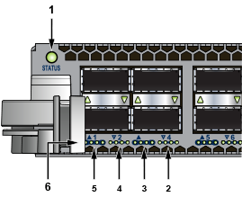
| 1 | Status LED | 2 | QSFP port 4 LEDs | 3 | QSFP port 3 LEDs |
| 4 | QSFP port 2 LEDs | 5 | QSFP port 1 LEDs | 6 | 10G / 40G /100G QSFP port LEDs |
Table 3 interprets the states of the status LED.
| LED State | Status |
|---|---|
| Off | Linecard not inserted. |
| Green | Linecard operating normally. |
| Yellow | Linecard administratively shut down. |
| Red | Linecard has failed. |
The linecard provides LEDs for each port module socket:
- Each LED corresponds to a module.
- A set of four LEDs correspond to each module. When the module is programmed as a 40G port, the first LED in the set reports status. When the module is programmed as four 10G or 100G ports, each port is assigned to an LED within the set.
Table 4 interprets the port LED states.
| LED State | Status |
|---|---|
| Off | Port link is down. |
| Green | Port link is up. |
| Yellow | Port is disabled in software. |
Fabric Status Indicators
Fabric Status LEDs are on fan-fabric modules. The Rear Panel displays the position of these LEDs on the rear of each switch. Figure 5 display fan status and fabric status LEDs on the switch.
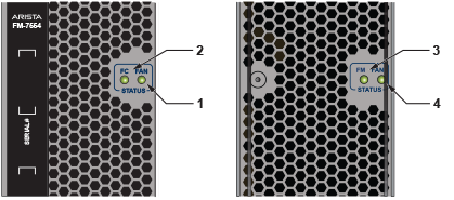
| 1 | Fan status LED | 3 | Fabric status LED |
| 2 | Fabric status LED | 4 | Fan status LED |
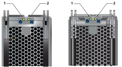
| 1 | Fabric status LED | 2 | Fan status LED |
Table 5 interpret the fan and fabric status LED states.
| LED State | Status |
|---|---|
| Off | Module inserted, but the status is unknown. |
| Green | Module operates normally |
| Red | Module failed |
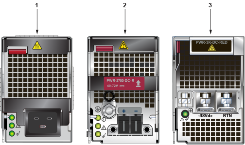
Power Supply Status Indicators
- PWR-3KT-AC RED
- PWR-2700-DC-R
- PWR-3K-DC-RED
The power supply LEDs are on the power supply modules. The positions of the LEDs are on the rear of each switch. Figure 7 display all the power supply modules supported on the 7500N.
- DC Good
- Fault, and
- Vin Good
Table 6 interprets the power supply set up for LED status indicators.
| Power Supply State | LED Name | PWR-3KT-AC-Red | PWR-2700-DC-R | PWR-3K-DC-Red |
|---|---|---|---|---|
| Input power present Normal Operation | DC Good Fault Vin Good | Green Off Green | Green Off Green | Green |
| Input power present Main output off | DC Good Fault Vin Good | Off Off Green | Off Off Green | Blinking Green |
| Input power present Power Supply Fault | DC Good Fault Vin Good | Off Blinking Amber Green | Off Blinking Amber Green | Blinking Amber, 1 sec on, 1 sec off |
| No Input Power Supply installed in chassis | DC Good Fault Vin Good | Off Off Off | Off Off Off | Off |
| Input power present Supply not seated in chassis | DC Good Fault Vin Good | Off Off Blinking Green | Off Off Off | Blinking Amber, 0.5 sec on/off |