
Front Panel
This section displays the front panel of all Arista NDR appliances this guide covers.
Note: All devices are designed to fit into a 19” rack. The appearance may be different than those shown based on PSU and fan modules used.
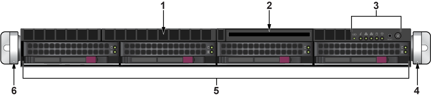
| 1 | Unused port | 2 | Unused port | 3 | Control panel |
| 4 | Right rack ear bracket | 5 | Storage drives | 6 | Left rack ear bracket |
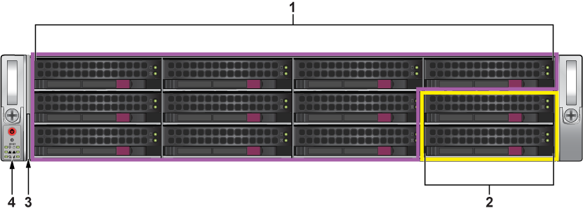
| 1 | Storage drives | 2 | NVMe - A5, NB10, and CC only | 3 | Service/Asset tag |
| 4 | Control panel |
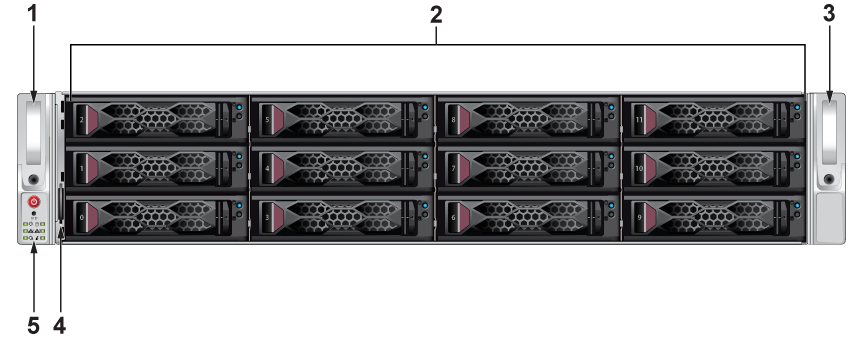
| 1 | Left rack ear bracket | 2 | Purple - hot-swap SAS drives | 3 | Right rack ear bracket |
| 4 | Service/Asset Tag with BMC Password | 5 | Control Panel |
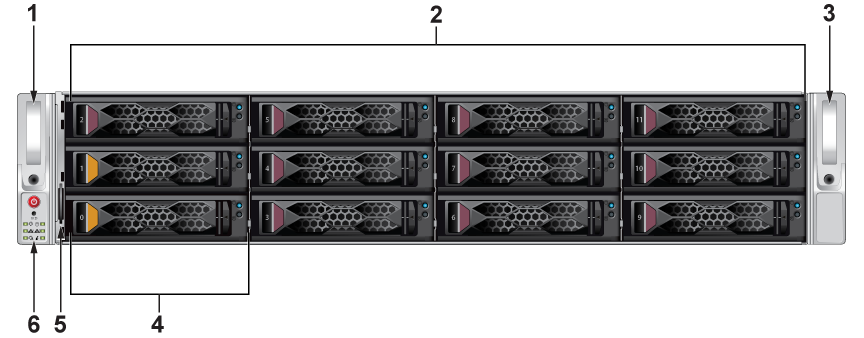
| 1 | Left rack ear bracket | 2 | Purple - hot-swap SAS drives | 3 | Right rack ear bracket |
| 4 | Orange - hot-swap NVMe drives | 5 | Service/Asset Tag with BMC Password | 6 | Control Panel |
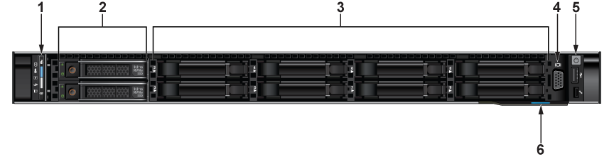
| 1 | Status LEDS | 2 | Hot-Swap NVMe Bays | 3 | Blank Drive Bays |
| 4 | VGA Port | 5 | Power button and Ports | 6 | Express Service Tag |
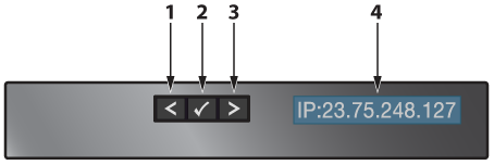
| 1 | Moves the cursor back in one-step increments. | 2 | Selects the menu item that is highlighted by the cursor. | 3 | Moves the cursor forward in one-step increments. |
| 4 | LCD Display: Displays the system information, status, and error messages; or IPMI IP address. |
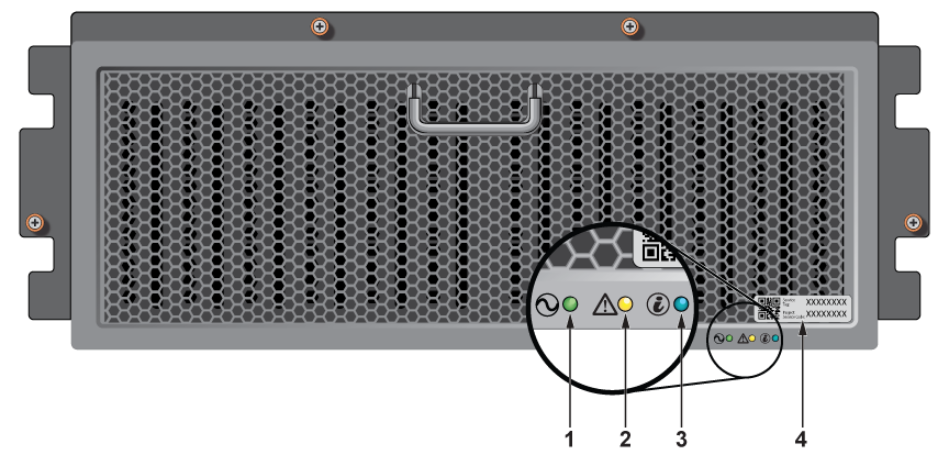
| 1 | System power LED | 2 | System status LED | 3 | Enclosure ID LED |
| 4 | Express Service tag |