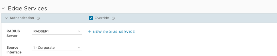
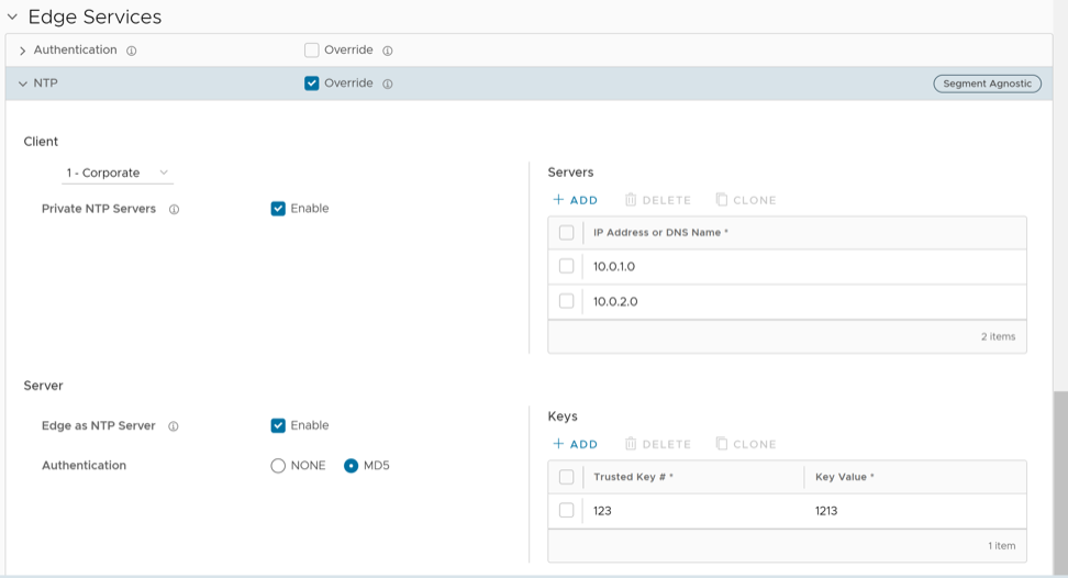
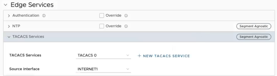
Select the link to an Edge or select the View link in the Device column of the Edge.
The configuration options for the selected Edge are displayed on the Device tab.
Figure 1. Device Tab
Select View to expand or collapse the view of available settings.
Users can also view the configuration settings sorted by category or segmentation. By default, the settings are sorted by category. Sorting by segmentation groups the settings into segment-aware and segment-agnostic categories.
For some of the settings, the configuration is inherited from the associated Profile. To edit the inherited configuration for the Edge, select the Override checkbox. The following settings appear when sorting by category:
Table 1. Connectivity
Option
Description
VLAN
Configure the VLANs with both IPv4 and IPv6 addresses for Edges. Select the IPv4 or IPv6 tabs to configure the corresponding IP addresses for the VLANs. For additional information, see Configure VLAN for Edges.
Note: Whencreating a new VLAN or edit a VLAN configuration using the new Orchestrator UI, the VLAN appears as read-only in the classic Orchestrator UI. After creating or editing a VLAN with new Orchestrator UI,modify the settings of the corresponding VLAN only in the new Orchestrator UI.
Loopback Interfaces
Configure a logical interface to assign an IP address, which identifies an Edge. For additional information., see Loopback Interfaces Configuration.
Management Traffic
Configure management traffic by selecting a source IP for the Edge to transmit traffic to the Orchestrator. For additional information, see Configure Management Traffic for Edges.
ARP Timeouts
By default, the Edge inherits the ARP settings from the associated Profile. Select the Override and Override default ARP Timeouts checkboxes to modify the values. For additional information, see Configure Address Resolution Protocol Timeouts for Edges.
Interfaces
Configure the following settings for the Edge Interfaces:
Interface Settings – Configure the settings for a Switch Port (LAN) or a Routed (WAN) Interface of the selected Edge. See Configure Interface Settings for Edges.
WAN Overlay Settings – Enables to add or modify a User-Defined WAN Overlay and modify or delete an existing auto-detected WAN Overlay. See Configure Edge WAN Overlay Settings.
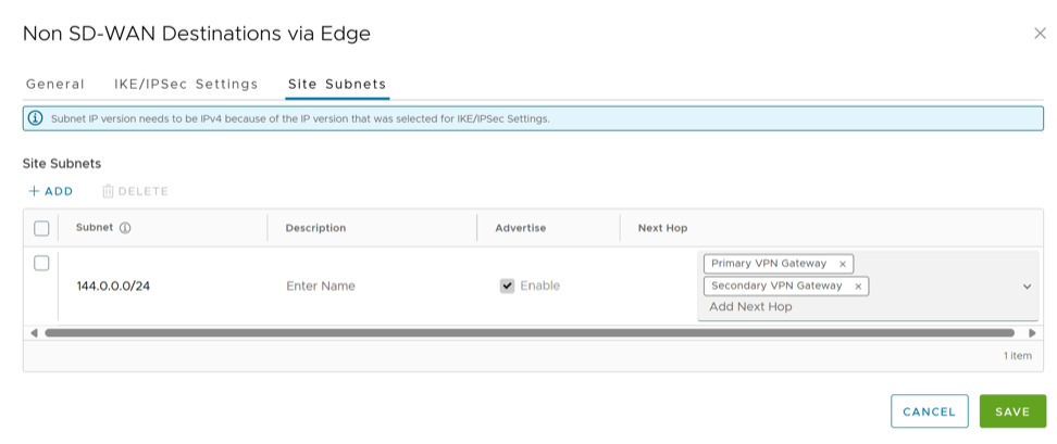
Enable to establish tunnel between a branch and Non SD-WAN destination via Edge. See Configure Tunnel Between Branch and Non SD-WAN Destinations via Edge. Select Add to add Non SD-WAN Destinations. Select New NSD via Edge to create new Non SD-WAN Destination via Edge. See Configure a Non SD-WAN Destinations via Edge.
Cloud Security Service
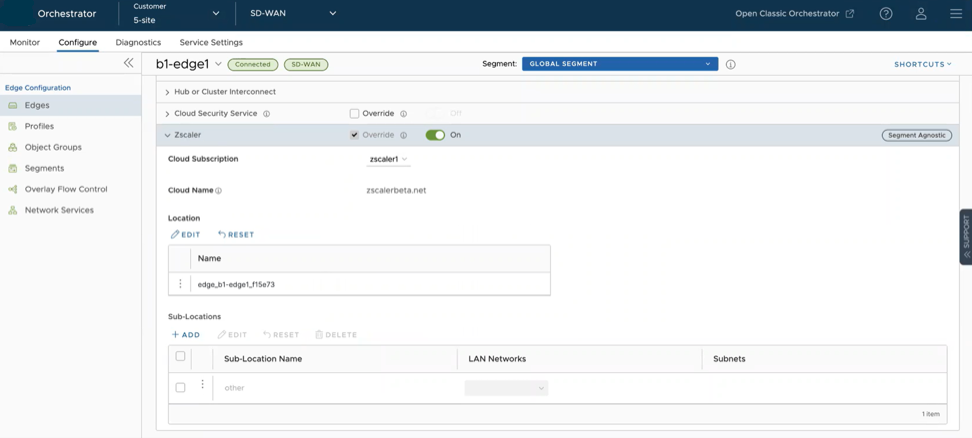
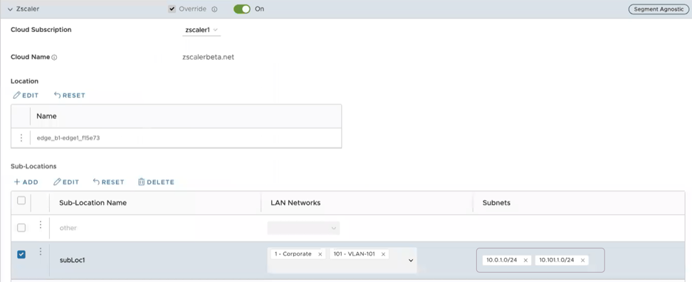
Enable to establish a secured tunnel from an Edge to cloud security service sites. This enables the secured traffic being redirected to third-party cloud security sites. See Configure Cloud Security Services for Edges.
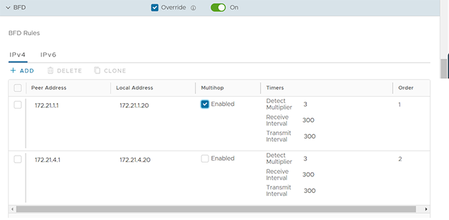
By default, the Edge inherits the BFD configuration settings from the associated Profile. If required, select the Override checkbox to modify the settings. For additional information, see Configure BFD for Edges.
LAN-Side NAT Rules
Allows NAT IP addresses in an unadvertised subnet to IP addresses in an advertised subnet. See LAN-side NAT Rules at Edge Level.
ICMP Probes
Configure ICMP probes that check for the network continuity by pinging specified IP address at frequent intervals. See Configure ICMP Probes and Responders.
Configure Static Route Settings for special cases in which static routes are needed for existing network attached devices, such as printers. See Configure Static Route Settings.
DNS
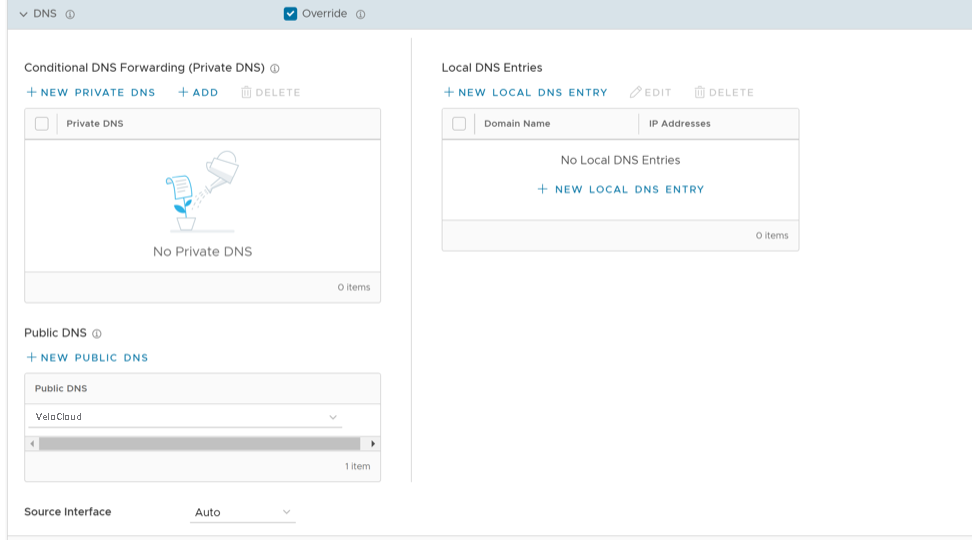
Use the DNS Settings to configure conditional DNS forwarding through a private DNS service and to specify a public DNS service to be used for querying purpose. See Configure DNS for Edges.
OSPF Areas
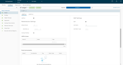
The OSPF settings configured in the associated Profile are displayed. Configure OSPF areas only for a Profile and for a Global Segment. Configure additional OSPF settings for routed interfaces on Edges. For additional information, see Configure OSPF for Edges.
BGP
Configure BGP settings for Underlay Neighbors and Non SD-WAN Neighbors. See Configure BGP.
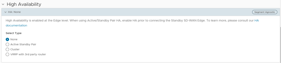
Enable High Availability for the selected Edge. Choose one of the following options:
None – This is the default option where High Availability is not enabled.
Active Standby Pair – Select this option to enable HA on the selected Edge. For additional information, see Activate High Availability.
Cluster – Select an existing Edge cluster from the drop-down list to enable High Availability on the Edge cluster. To configure Edge clusters, see Monitor Edge Clusters.
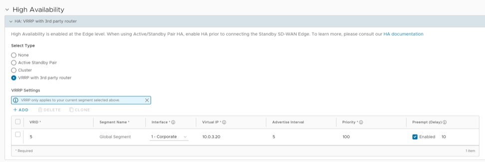
VRRP with 3rd party router – Select this option to configure Virtual Router Redundancy Protocol (VRRP) on the selected Edge to enable next-hop redundancy in the SD-WAN Orchestrator network by peering with third-party CE router. To configure VRRP, see Configure VRRP Settings.
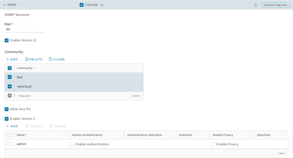
Enable the required SNMP version for monitoring the network. Ensure to download and install all the required SNMP MIBs before enabling SNMP. See Configure SNMP Settings for Edges.
Syslog
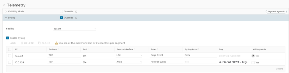
Configure Syslog collector to receive Orchestrator bound events and firewall logs from the Edges configured in an Enterprise. See Configure Syslog Settings for Edges.
Table 6. Security VNF
Option
Description
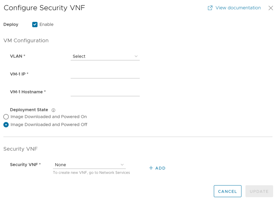
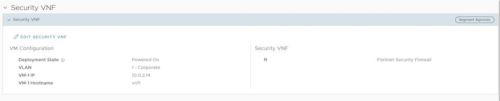
Security VNF
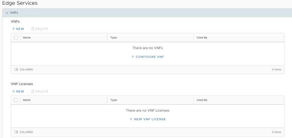
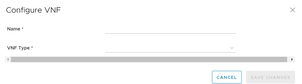
Configure security VNF to run the functions of a network service in a software-only form. For additional information, see Security Virtual Network Functions.
After modifying the required settings, select Save Changes.
Select the Shortcuts option to perform the following activities:
Monitor – Navigates to the Monitoring tab of the selected Edge. See Monitor Edges.
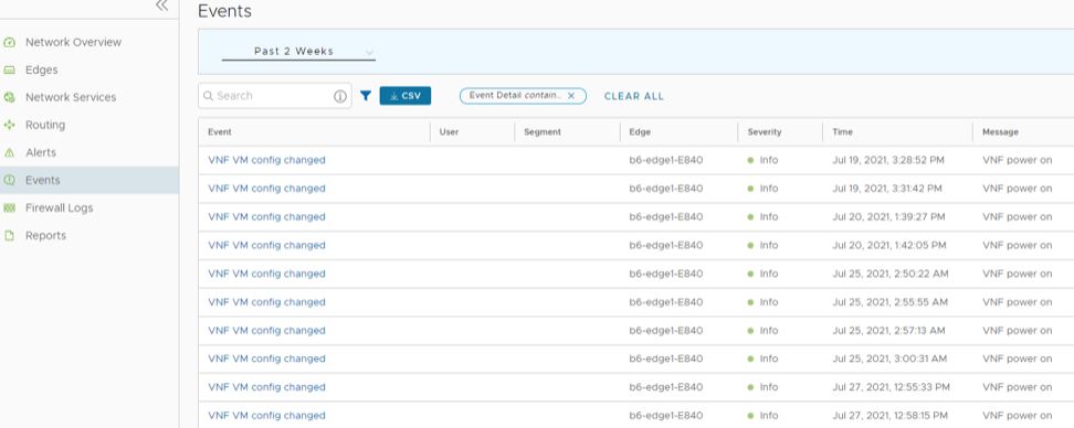
View Events – Displays the Events related to the selected Edge.
Remote Diagnostics – Enables to run the Remote Diagnostics tests for the selected Edge. See Run Remote Diagnostics.
Generate Diagnostic Bundle– Allows to generate Diagnostic Bundle for the selected Edge. See Diagnostic Bundles for Edges.
Remote Actions – Allows to perform the Remote actions for the selected Edge. See Perform Remote Actions.
View Profile – Navigates to the Profile page, that is associated with the selected Edge.
View Gateways – Displays the Gateways connected to the selected Edge.
Configure VLAN for Edges
At the Edge level, add a new VLAN or update the existing VLAN settings inherited from the associated Profile. When configuring a new VLAN at the Edge level, the Orchestrator allows configuring additional Edge-specific VLAN settings, such as Fixed IP addresses, LAN interfaces, and the Service Set Identifier (SSID) for Wi-Fi interfaces.
Note:
Configure up to 32 VLANs across 16 Segments on an Edge.
On Profile change, the target profile removes any VLAN inherited from the Edges profile from the target Profile unless overridden at the Edge level. Any interface associated with a removed VLANsreverts to the Profile-level configuration in the target Profile, even if Edge overrides the interface.
To configure VLAN settings for an Edge, use the following steps:
In the SD-WAN service of the Enterprise portal, select Configure > Edges.
Select the link to an Edge or select the View link in the Device column of the Edge.
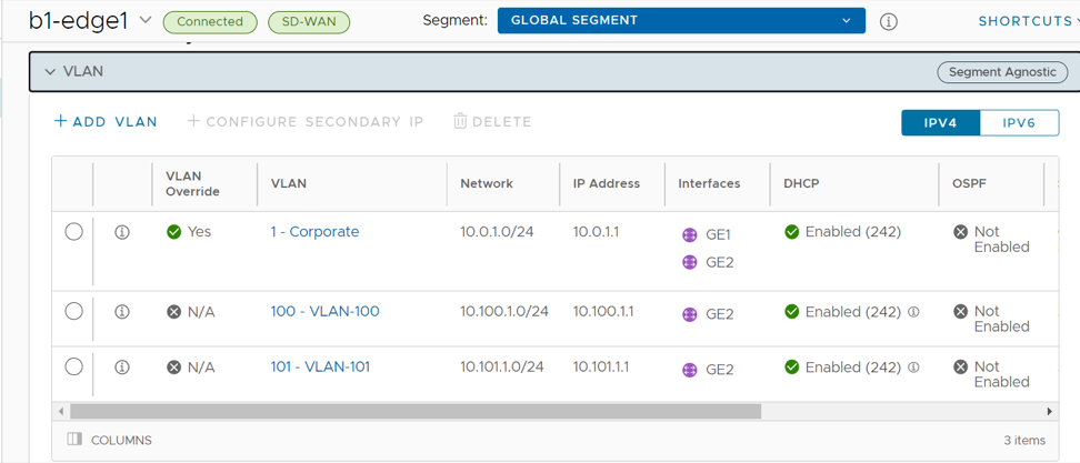
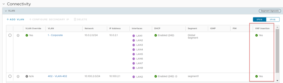
On the Device tab, under Connectivity, expand the VLAN section.
Figure 2. VLAN Settings
Add, edit, or delete VLANs, and assign secondary IP addresses.
Select IPv4 or IPv6 button to display the respective list of VLANs.
To add a VLAN, select + Add VLAN.
Figure 3. Add VLAN
Configure the following options:
Table 8. Add VLAN - Options and Descriptions
Option
Description
Segment
Select a segment from the menu. This assigns the VLAN to the selected segment.
VLAN Name
Enter a unique name for the VLAN.
VLAN ID
Enter the VLAN ID.
Assign Overlapping Subnets
Manage LAN IP Addressing from the assigned Profile of the Edge. When selected, the values for Edge LAN IP Address, Cidr Prefix, and DHCP inherit from the associated Profile and become read-only. The Network address automatically sets based on the subnet mask and CIDR value.
Note: Only SD-WAN to SD-WAN traffic and SD-WAN to Internet traffic support overlapping subnets for the VLAN .
Edge LAN IP Address
Enter the LAN IP address of the Edge.
Cidr Prefix
Enter the CIDR prefix for the LAN IP address.
Network
Enter the IP address of the Network.
Advertise
Select the check box to advertise the VLAN to other branches in the network.
ICMP Echo Response
Select the check box to enable the VLAN to respond to ICMP echo messages.
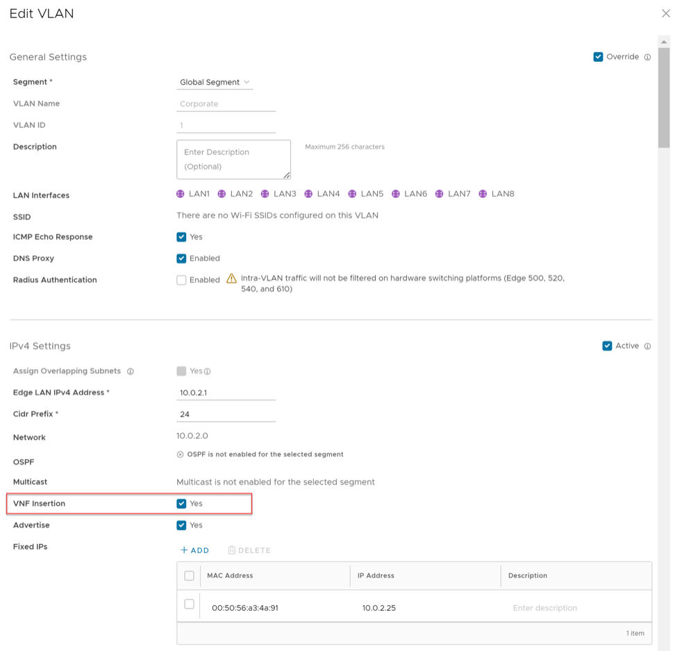
VNF Insertion
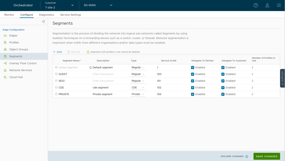
Select the check box to insert a VNF to the VLAN, which redirects traffic from the VLAN to the VNF. To enable this option, ensure that the selected segment is mapped with a service VLAN.
Multicast
Configuring multicast settings for the Edge enables this option. The following multicast settings apply to the VLAN:
IGMP
PIM
Select toggle advanced multicast settings to set the timers:
PIM Hello Timer
IGMP Host Query Interval
IGMP Max Query Response Value
Fixed IPs
Enter the IP addresses tied to specific MAC Addresses for the VLAN.
LAN Interfaces
Configure VLAN LAN Interfaces.
SSID
Configure VLAN Wi-Fi SSIDs.
DHCP Type
Choose one of the following DHCP settings:
Enabled - Enables DHCP with the Edge as the DHCP server. Configure the following details:
DHCP Start - Enter a valid IP address available within the subnet.
Num. Addresses - Enter the number of IP addresses available on a subnet in the DHCP Server.
Lease Time - Select the period of time from the menu. This sets the duration that the VLAN uses an IP address dynamically assigned by the DHCP Server.
Options - Add pre-defined or custom DHCP options. The DHCP option provides a network service passed to the clients from the DHCP server. For a custom option, enter the code, data type, and value.
Relay: Enables DHCP with the DHCP Relay Agent installed at a remote location. Selecting this option requires the following configuration:
Source from Secondary IP(s): Triggers the relay of DHCP Discover/Request packets from the client to the DHCP Relay servers, sourced from the primary and all secondary IP addresses configured for the VLAN. The system then sends the reply from the DHCP Relay servers back to the client after rewriting the source and destination. Because the DHCP server receives requests from both primary and secondary IP addresses, the DHCP client may receive multiple offers from both primary and secondary subnets. Leaving this option unselected limits the relay of DHCP Discover/Request packets to the primary IP address source only.
Relay Agent IP(s): Specify the IP address of Relay Agent. Select the plus icon to add additional IP addresses.
Not Enabled: Deactivates DHCP.
OSPF
Available only when configuring OSPF at the Profile level for the selected Segment. Select and choose an OSPF area.
Note: The OSPFv2 configuration supports only IPv4. The OSPFv3 configuration supports only IPv6 only available in the 5.2 release.
After configuring the required parameters, select Add VLAN.
To edit existing VLAN settings inherited from the Profile:
Select the Edit link corresponding to the VLAN.
Select Override to override the VLAN settings inherited from the Profile.
Figure 4. Edit VLAN
Note: The system prevents overriding the Profile VLAN name and ID.
After modifying the required parameters, select Done VLAN. For Configuring VLANs at the Profile level, see Configure VLAN for Profiles.
Configure the VLAN with a primary IP address. Adding secondary IP addresses to a VLAN increases the number of available host addresses on a network segment. To add secondary IP addresses to the VLAN, use the following steps:
Select Add Secondary IP.
A new row to configure a secondary IP appears.
Figure 5. Configure Secondary IP
Configure the Secondary IP VLAN settings:
Table 9. Configure Secondary IP - Options and Descriptions
Option
Description
Addressing Type
By default, the addressing type is Static, and it is not possible to modify the type.
IP Address
Enter the secondary IP address for the selected VLAN.
Cidr Prefix
Enter the CIDR prefix for the IP address.
Network
Displays the IP address of the Network, which is auto-generated from the secondary IP address and CIDR prefix.
Advertise
Select the check box to advertise the secondary IP address network of the VLAN to other branches in the network.
ICMP Echo Response
Select the check box to enable the VLAN with the secondary IP address to respond to ICMP echo messages.
Select (+ ADD) to add additional IP addresses to the VLAN.
Note: The system supports up to 16 secondary IP addresses per VLAN.
Select Done when complete.
On the Device settings screen, select Save Changes to save the settings.
Loopback Interfaces Configuration
A loopback interface is a logical interface that allows users to assign an IP address to identify a VeloCloud Edge.
Loopback interface configuration requires Edge version 4.3 or above. The Configure Loopback Interfaces area is not available for Edges running version 4.2 or lower. For such Edges, users must configure the Management IP address. For details, refer to Configure Management IP Address for Profiles.
Following are the benefits of configuring loopback interfaces for an Edge:
As loopback interfaces are logical interfaces that are always up and reachable, use them for diagnostic purposes as long as there is Layer 3 reachability to at least one physical interface.
Loopback interfaces serve as the source interface for BGP. This ensures that when the BGP interface state flaps, the BGP membership does not flap if at least one Layer 3 connection remains available.
The loopback interface IP address serves as the source IP for various services, including Orchestrator Management Traffic, Authentication, DNS, NetFlow, Syslog, TACACS, BGP, and NTP. As loopback interfaces are always up and reachable, these services can receive the reply packets if at least one physical interface configured for the Edge has layer 3 reachability.
Loopback Interfaces—Limitations
Remember the following limitations before users configure loopback interfaces for their Edges:
The system supports only IPv4 addresses for loopback interfaces.
Loopback interfaces apply exclusively to Edges and do not support Profile-level configuration.
Configure loopback interfaces only after successful Edge activation.
For any Edge that is not activated, the customer operator profile version is determined by whether the Management IP Address section or the Loopback Interfaces section is visible. For example, if the customer operator profile version is 4.3 or higher, the Loopback Interfaces section is visible at the Edge level. However, if the customer operator profile version is 4.2 or lower and the Edge is not activated, the Management IP Address section is visible at the Edge and Profile levels.
Loopback interface IDs must be unique across all segments within an Edge. These IDs start from 1, as the system does not support zero (0).
Configuring loopback interfaces and Orchestrator management traffic via API removes the availability of the default configuration keys for these properties. The user must modify the updateConfigurationModule API to configure the loopback interface and select the management traffic source interface.
Access loopback interfaces through SSH only. Loopback interface access through local Web UI is not supported.
Consider the following while upgrading or downgrading Edges:
If the Management IP address that is configured either at the Profile-level or at the Edge-level is not the default IP address (192.168.1.1) and when the Edge is upgraded to version 4.3 or above, the loopback interface is automatically created at the Edge-level with the configured Management IP address as the IP address of the loopback interface.
Consider upgrading Orchestrator to version 4.3 or above, whereas the Edge still runs on version 4.2 or lower. If users update the Management IP address configuration either at the Profile-level or at the Edge-level, and then upgrade the Edge to version 4.3 or above, all changes that users made to the Management IP address configuration will be lost.
Downgrading the Edge to a version earlier than 4.3 restores the previously configured Management IP address at both the Profile and Edge levels.
An Edge downgrade erases any changes made to the loopback interface configuration.
For example, assume users had the Management IP address set to 1.1.1.1. When users upgrade their Edge to version 4.3 or above, the same IP address, 1.1.1.1, will be the IP address of the loopback interface at the Edge level. Then, users change the loopback interface IP address to 2.2.2.2. When users downgrade their Edge to a version lower than 4.3, users will notice that the Management IP address at the Edge-level will still be 1.1.1.1 and the Management IP address at the Profile-level will be empty.
Configure a Loopback Interface for an Edge
There are a few rules and limitations to consider when configuring a loopback interface. For additional information, see Loopback Interfaces—Limitations.
To configure a loopback interface for an Edge, perform the following steps:
In the SD-WAN service of the Enterprise portal, go to Configure > Edges.
Select the link to an Edge to configure the loopback interface or select the View link in the Device column of the Edge. The Device tab displays the configuration options for the selected Edge.
Scroll down to the Connectivity category and select Loopback Interfaces.
Figure 6. Loopback Interfaces
Select + Add and in the Add Loopback pop-up window, configure the required loopback settings as described in the following table.
Figure 7. Add Loopback
Table 10. Add Loopback - Options and Descriptions
Option
Description
Interface ID
Enter a unique ID for the loopback interface. The ID requires uniqueness across all segments within an Edge and starts from 1, as the system does not support Zero (0).
Segment
Select a segment from the drop-down list. The loopback interface belongs to the selected segment.
ICMP Echo Response
Select the checkbox to enable the loopback interface to respond to ICMP echo messages.
Enable IPv4 Settings
Addressing Type
By default, the addressing type is Static and users cannot modify the type.
IP Address
Enter the IPv4 address for the loopback interface.
CIDR Prefix
The CIDR prefix for the loopback interface IPv4 address. The default value is /32. Users cannot modify the default value.
Advertise
Select the checkbox to advertise the loopback interface to other branches in the network.
OSPF
Select the checkbox and choose an OSPF area from the drop-down list. The loopback interface IP address is advertised in the selected OSPF area.
Note:
The OSPFv2 configuration supports only IPv4. The OSPFv3 configuration supports only IPv6, which is only available in the 5.2 release.
Configuring OSPF for the segment selected for the loopback interface enables this option.
By default, the addressing type is Static and users cannot modify the type.
IP Address
Enter the IPv6 address for the loopback interface.
CIDR Prefix
The CIDR prefix for the loopback interface IP address. The default value is /128. Users cannot modify the default value.
Note: Select the Active check boxes for the IPv4 and IPv6 settings, to enable the corresponding addressing type for the Interface. By default, the option is enabled for IPv4 settings.
Select Add.
Select Save Changes.
The Loopback Interfaces section displays the configured interface. The Address link allows editing loopback interface settings at any time, except for the CIDR Prefix and Interface fields.
Deleting a loopback interface resets the Source Interface field to Auto for all associated services.
Interface ID.
Additionally, two further scenarios trigger a reset of the Source Interface to Auto for various services:
The Edge fails to locate the loopback interface ID.
Selecting older API versions to configure the Edge sometimes prevents the Edge from receiving the source IP address key for services.
When the Source Interface field for any service defaults to Auto, the Edge selects the source interface based on the following criteria:
The system prioritizes any advertised non-WAN interface.
Among advertised non-WAN interfaces, the system selects the source interface according to this priority order: Loopback interfaces, VLAN interfaces, and routed interfaces.
If more than one interface of the same type is configured and advertised, the interface with the lowest interface ID is selected. For example, if users have two loopback interfaces (LO3 and LO4), one VLAN interface (VLAN2), and two routed interfaces (GE1 and GE2) configured and advertised, and if the Source Interface field for any service is set to Auto, the Edge selects LO3 as the source interface.
A configured loopback interface becomes available as a source interface for the services listed below:
Note: When the Edge transmits traffic, the packet header carries the IP address of the selected source interface, while the destination route determines the specific egress interface for the packets.
Configure Management Traffic for Edges
VeloCloud Orchestrator allows to configure the Management Traffic for the Edge. To configure the Management Traffic at the Edge level, perform the following steps:
In the SD-WAN service of the Enterprise portal, go to Configure > Edges.
Select either the Edge link or the View link in the Device column to open the configuration page. The Device tab then displays the configuration options for the selected Edge.
Scroll down to the Connectivity category and select and expand the Management Traffic area.
Figure 8. Management Traffic
The Source Interface drop-down menu provides available Edge interfaces configured for the segment. The selected interface serves as the source IP for traffic transmission to the VeloCloud Orchestrator. By default, the system selects Auto.
From the Source Interface drop-down menu. Selection of an Edge interface configured for the segment defines the source IP for traffic transmission to the VeloCloud Orchestrator. The system defaults this selection to Auto.
The packet header carries the IP address of the selected source interface during transmission, while the destination route determines the specific egress interface for the packets.
Configure Address Resolution Protocol Timeouts for Edges
At the Edge level, select the Override checkbox to override the Address Resolution Protocol (ARP) Timeout settings inherited from a Profile.
To override the ARP timeouts values at the Edge-level, perform the following steps:
In the SD-WAN service of the Enterprise portal, go to Configure > Edges.
The Edges page displays the existing Edges.
Select the link to an Edge for which users want to configure the Layer 2 settings or select the View link in the Device column of the Edge.
The Device tab displays the configuration options for the selected Edge.
Under the Connectivity category, select ARP Timeouts and select the Override checkbox.
Figure 9. ARP Timeouts
Select the Override default ARP Timeouts checkbox, and then override the various ARP timeouts inherited from the Profile as follows:
Table 12. ARP Timeouts - Options and Descriptions
Option
Description
ARP Stale Timeout
The allowable value ranges from 1 minute to 23 hours and 58 minutes.
ARP Dead Timeout
The allowable value ranges from 2 minutes to 23 hours and 59 minutes.
ARP Cleanup Timeout
The allowable value ranges from 3 minutes to 24 hours.
To set the default ARP timeout values at the Edge level, de-select the Override default ARP Timeouts checkbox.
Select Save Changes.
Configure Interface Settings for Edges
Edges support various interface types and initially inherit configuration settings from the associated Profile. Each Edge model offers unique interface options and supports local modifications to these settings. For additional information on different Edge models and deployments, see Configure Interface Settings.
Perform the following steps, to configure interface settings for a specific Edge.
Select Configure > Edges, in the SD-WAN Service of the Enterprise portal,
The Edges page displays the existing Edges.
Select the link to an Edge or select the View link in the Device column of the Edge. The configuration options for the selected Edge are displayed in the Device tab.
In the Connectivity category, expand Interfaces.
The available interface types for the selected Edge are displayed. Select the link to an interface to edit the settings.
The Interface settings screen appears.
Figure 10. Interface Settings
Based on the Edge model, users can edit the settings for the following types of interfaces:
Switch Port
Routed Interface
WLAN Interface
Based on the Edge model the user can also add Subinterface, Secondary IP address, and Wi-Fi SSID.
Table 13. Interface Settings - Options and Descriptions
Option
Description
Description
Enter a description. This field is optional.
Interface Enabled
This option remains active by default. If required, users can deactivate the interface. When deactivated, the interface is unavailable for communication.
Capability
The system selects the Switched option for switch ports by default. Users can convert the port to a routed interface by selecting Routed from the drop-down menu.
Segments
By default, the configuration settings apply to all segments.
Radius Authentication
Deactivate the Enable WAN Overlay checkbox to configure Radius Authentication. Select the Radius Authentication checkbox and add the MAC addresses of pre-authenticated devices.
ICMP Echo Response
The system selects this checkbox by default. This helps the interface respond to ICMP echo messages. Users can deactivate this option for security purposes.
Underlay Accounting
The system selects this checkbox by default. If a private WAN overlay is defined on the interface, all underlay traffic traversing the interface are counted against the measured rate of the WAN link to prevent over-subscription. Deactivate this option to avoid this behavior.
Underlay Accounting is supported for both, IPv4 and IPv6 addresses.
Enabling underlay configuration for LAN is not recommended.
Enable WAN Overlay
Select the checkbox to activate WAN overlay for the interface.
DNS Proxy
The DNS Proxy feature provides additional support for Local DNS entries on the Edge to point certain device traffic to specific domains. The system supports activating or deactivating this option regardless of the IPv4 or IPv6 DHCP Server settings. This checkbox appears only for routed interfaces and routed subinterfaces.
VLAN
For an Access port, select an existing VLAN from the drop-down menu. For a Trunk port, users can select multiple VLANs and select an untagged VLAN.
EVDSL Modem Attached
Select this checkbox to activate an EVDSL Modem which is connected to one of the Ethernet ports on the Edge.
IPv4 Settings
Select the Enable checkbox and configure the IPv4 settings. For additional information, see the IPv4 Settings section below.
IPv6 Settings
Select the Enable checkbox and configure the IPv6 settings. For additional information, see the IPv6 Settings section below.
L2 Settings
Autonegotiate
This option is selected by default. When selected, Auto negotiation allows the port to communicate with the device on the other end of the link to determine the optimal duplex mode and speed for the connection.
Speed
This option is available only when Autonegotiate is not selected. Select the speed that the port has to communicate with other links. By default, 100 Mbps is selected.
Duplex
This option is available only when Autonegotiate is not selected. Select the mode of the connection as Full duplex or Half duplex. By default, Full duplex is selected.
MTU
The default MTU size for frames received and sent on all routed interfaces is 1500 bytes. Users can change the MTU size for an interface.
LOS Detection
This option is available only for a routed interface of an Edge. Select the checkbox to activate Loss of Signal (LoS) detection by using ARP monitoring. For additional information, see HA LoS Detection on Routed Interfaces
Note: Select the checkbox only when the users have activated High Availability on the Edge.
Configure the following settings for a Routed interface of an Edge.
Table 14. Routed Interface - Options and Descriptions
Option
Description
Description
Enter a description. This field is optional.
Interface Enabled
This option is activated by default. If required, users can deactivate the interface. When deactivated, the interface is not available for any communication.
Capability
For a Switch Port, the option Switched is selected by default. Users can convert the port to a routed interface by selecting the option Routed from the drop-down menu.
Segments
By default, the configuration settings are applicable to all the segments.
Radius Authentication
Deactivate the Enable WAN Overlay checkbox to configure Radius Authentication. Select the Radius Authentication checkbox and add the MAC addresses of pre-authenticated devices.
ICMP Echo Response
This checkbox is selected by default. This helps the interface to respond to ICMP echo messages. Users can deactivate this option for security purposes.
Underlay Accounting
This checkbox is selected by default. If a private WAN overlay is defined on the interface, all underlay traffic traversing the interface are counted against the measured rate of the WAN link to prevent over-subscription. Deactivate this option to avoid this behavior.
Underlay Accounting is supported for both, IPv4 and IPv6 addresses.
Enabling underlay configuration for LAN is not recommended.
Enable WAN Overlay
Select the checkbox to activate WAN overlay for the interface.
DNS Proxy
The DNS Proxy feature provides additional support for Local DNS entries on the Edge to point certain device traffic to specific domains. Users can activate or deactivate this option, irrespective of IPv4 or IPv6 DHCP Server setting. This checkbox is available only for a Routed Interface and a Routed Subinterface.
VLAN
For an Access port, select an existing VLAN from the drop-down menu. For a Trunk port, users can select multiple VLANs and select an untagged VLAN.
EVDSL Modem Attached
Select this checkbox to activate an EVDSL Modem which is connected to one of the Ethernet ports on the Edge.
IPv4 Settings
Select the Enable checkbox and configure the IPv4 settings. For additional information, see the IPv4 Settings section below.
IPv6 Settings
Select the Enable checkbox and configure the IPv6 settings. For additional information, see the IPv6 Settings section below.
L2 Settings
Autonegotiate
Speed
This option is available only when Autonegotiate is not selected. Select the speed that the port has to communicate with other links. By default, 100 Mbps is selected.
Duplex
This option is available only when Autonegotiate is not selected. Select the mode of the connection as Full duplex or Half duplex. By default, Full duplex is selected.
MTU
The default MTU size for frames received and sent on all routed interfaces is 1500 bytes. Users can change the MTU size for an interface.
LOS Detection
This option is available only for a routed interface of an Edge. Select the checkbox to activate Loss of Signal (LoS) detection by using ARP monitoring. For additional information, see HA LoS Detection on Routed Interfaces. The user can select the checkbox only when High Availability on the Edge is activated.
IPv4 Settings
Select the Enabled checkbox to configure the following IPv4 Settings:
Table 15. IPv4 Settings - Options and Descriptions
Option
Description
Addressing Type
Select an addressing type:
DHCP: Assigns an IPv4 address dynamically.
PPPoE: The user must configure the authentication details for each Edge. PPPoE requires authentication to get a dynamically assigned IP address.
Static: Enter the IP address, CIDR Prefix, and Gateway for the selected routed interface.
Note: 31-bit prefixes are supported for IPv4 as per RFC 3021.
OSPF
Configuring OSPF at the Profile level for the selected segment enables this option. Select the checkbox and choose an OSPF area from the drop-down menu. Select Advanced settings to configure the advanced interface settings for the selected OSPF area.
Note: When configuring advanced OSPF area settings for a routed interface, the BFD configuration is supported only for global segments.
The OSPFv2 configuration supports only IPv4. The OSPFv3 configuration supports only IPv6.
Note: OSFPv3 is only available in the 5.2 release.
This option is available only when configuring multicast settings for the selected Segment. Users can configure the following multicast settings for the selected interface.
IGMP- Select the checkbox to activate Internet Group Management Protocol (IGMP). Only IGMP v2 is supported.
PIM – Select the checkbox to activate Protocol Independent Multicast. Only PIM Sparse Mode (PIM-SM) is supported.
Select toggle advanced multicast settings to configure the following timers:
PIM Hello Timer – The time interval at which a PIM interface sends out Hello messages to discover PIM neighbors. The range is from 1 to 180 seconds and the default value is 30 seconds.
IGMP Host Query Interval – The time interval at which the IGMP querier sends out host-query messages to discover the multicast groups with members, on the attached network. The range is from 1 to 1800 seconds and the default value is 125 seconds.
IGMP Max Query Response Value – The maximum time that the host has to respond to an IGMP query. The range is from 10 to 250 deciseconds, and the default value is 100 deciseconds.
Note: Currently, Multicast Listener Discovery (MLD) is deactivated. Hence, Edge does not send the multicast listener report when IPv6 address is assigned to interface. If there is a snooping switch in the network then not sending MLD report may result in Edge not receiving multicast packets which are used in Duplicate Address Detection (DAD). This results in DAD success even with duplicate address.
VNF Insertion
To activate VNF Insertion, deactivate WAN Overlay and select the Trusted Source checkbox. When inserting the VNF into Layer 3 interfaces or subinterfaces, the system redirects traffic from the Layer 3 interfaces or subinterfaces to the VNF.
Advertise
Select the checkbox to advertise the interface to other branches in the network.
NAT Direct Traffic
Select the checkbox to apply NAT for IPv4 to network traffic sent from the interface.
CAUTION: It is possible that an older version of the SASE Orchestrator inadvertently configured NAT Direct on a main interface with either a VLAN or subinterface configured. If that interface is sending direct traffic one or hops away, the customer would not observe any issues because the NAT Direct setting was not being applied. However, when an Edge is upgraded to 5.2.0 or later, the Edge build includes a fix for the issue (Ticket #92142) with NAT Direct Traffic not being properly applied, and there is a resulting change in routing behavior since this specific use case was not implemented in prior releases. In other words, because a 5.2.0 or later Edge now implements NAT Direct in the expected manner for all use cases, traffic that previously worked (because NAT Direct was not being applied per the defect) may now fail because the customer never realized that NAT Direct was checked for an interface with a VLAN or subinterface configured. As a result, a customer upgrading their Edge to Release 5.2.0 or later should first check their Profiles and Edge interface settings to ensure NAT Direct is configured only where they explicitly require it and to deactivate this setting where it is not, especially if that interface has a VLAN or subinterface configured.
Trusted Source
Select the checkbox to set the interface as a trusted source.
Reverse Path Forwarding
The user can choose an option for Reverse Path Forwarding (RPF) only when the Trusted Source checkbox is selected. This option allows traffic on the interface only when the system forwards return traffic through that same interface. This helps to prevent traffic from unknown sources, like malicious traffic, on an Enterprise network. The system drops packets from unknown incoming sources at the ingress without creating a flow. Select one of the following options from the drop-down menu:
Not Enabled – Allows incoming traffic even if there is no matching route in the route table.
Specific – This option is selected by default, even when the Trusted Source option is deactivated. The incoming traffic should match a specific return route on the incoming interface. If a specific match is not found, then the incoming packet is dropped. This is a commonly used mode on interfaces configured with public overlays and NAT.
Loose – The incoming traffic should match any route (Connected/Static/Routed) in the routing table. This allows asymmetrical routing and is commonly used on interfaces that are configured without next hop.
For IPv4 address, configure the IPv4 DHCP Server as follows:
Note: This option appears only when the user select the Addressing Type as Static.
Activated- Activates DHCP with the Edge as the DHCP server. Ifthe user chooses this option, configure the following details:
DHCP Start- Enter a valid IP address available within the subnet.
Num. Addresses- Enter the number of IP addresses available on a subnet in the DHCP Server.
Lease Time- Select the period of time from the drop-down menu. This is the duration the VLAN is allowed to use an IP address dynamically assigned by the DHCP server.
Options- Select Add to add pre-defined or custom DHCP options from the drop-down menu. The DHCP option is a network service passed to the clients from the DHCP server. Choose a custom option and enter the code, data type, and value.
Relay- Allows exchange of DHCPv4 messages between client and server. Ifthe user chooses this option, configure the following:
Relay Agent IP(s)- Specify the IP address of Relay Agent. Select Add to add additional IP addresses.
Deactivated- Deactivates the DHCP server.
IPv6 Settings
Select the Enabled checkbox to configure the following IPv6 Settings:
Table 16. IPv6 Settings - Options and Descriptions
Option
Description
Addressing Type
Select an addressing type:
DHCP Stateless:
DHCP Stateful:
Static: Enter the IP address, CIDR Prefix, and Gateway for the selected routed interface.
OSPF
This option is available only when the user has configured OSPF at the Profile level for the selected Segment. Select the checkbox and choose an OSPF area from the drop-down menu. Select Advanced Settings to configure advanced interface settings for the selected OSPF area.
Note: When configuring advanced OSPF area settings for a routed interface, the BFD configuration is supported only for global segments.
The OSPFv2 configuration supports only IPv4. The OSPFv3 configuration supports only IPv6, which is only available in the 5.2 release.
Note: OSFPv3 is only available in the 5.2 release.
Select the checkbox to advertise the interface to other branches in the network.
NAT Direct Traffic
Select the checkbox to apply NAT for IPv6 to network traffic sent from the interface.
CAUTION:It is possible that an older version of the SASE Orchestrator inadvertently configured NAT Direct on a main interface with either a VLAN or subinterface configured. If that interface is sending direct traffic one or hops away, the customer would not observe any issues because the NAT Direct setting was not being applied. However, when an Edge is upgraded to 5.2.0 or later, the Edge build includes a fix for the issue (Ticket #92142) with NAT Direct Traffic not being properly applied, and there is a resulting change in routing behavior since this specific use case was not implemented in prior releases. In other words, because a 5.2.0 or later Edge now implements NAT Direct in the expected manner for all use cases, traffic that previously worked (because NAT Direct was not being applied per the defect) may now fail because the customer never realized that NAT Direct was checked for an interface with a VLAN or subinterface configured. As a result, a customer upgrading their Edge to Release 5.2.0 or later should first check their Profiles and Edge interface settings to ensure NAT Direct is configured only where they explicitly require it and to deactivate this setting where it is not, especially if that interface has a VLAN or subinterface configured.
Trusted Source
Select the checkbox to set the Interface as a trusted source.
Reverse Path Forwarding
The user can choose an option for Reverse Path Forwarding (RPF) only when the Trusted Source checkbox is selected. This option allows traffic on the interface only when the system forwards return traffic through that same interface. This helps prevent traffic from unknown sources, such as malicious traffic, on an Enterprise network. The system drops packets from unknown incoming sources at ingress without creating a flow. Select one of the following options from the drop-down menu:
Not Enabled – Allows incoming traffic even if there is no matching route in the route table.
Specific – This option is selected by default, even when the Trusted Source option is deactivated. The incoming traffic should match a specific return route on the incoming interface. If a specific match is not found, then the incoming packet is dropped. This is a commonly used mode on interfaces configured with public overlays and NAT.
Loose – The incoming traffic should match any route (Connected/Static/Routed) in the routing table. This allows asymmetrical routing and is commonly used on interfaces that are configured without next hop.
For IPv6 address, configure the IPv6 DHCP Server as follows:
Note: This option appears only when the user select the Addressing Type as Static.
Activated- Activates DHCPv6 with the Edge as the DHCPv6 server. Ifthe user chooses this option, configure the following details:
DHCP Start- Enter a valid IPv6 address available within the subnet.
Num- Addresses: Enter the number of IP addresses available on a subnet in the DHCPv6 Server.
Lease Time- Select the period of time from the drop-down list. This is the duration the VLAN is allowed to use an IPv6 address dynamically assigned by the DHCPv6 Server.
DHCPv6 Prefix Delegation- Select Add to assign prefixes chosen from a global pool to DHCP clients. Enter the prefix pool name along with the prefix start and end details.
Options- Select Add to add pre-defined or custom DHCP options from the drop-down menu. The DHCP option is a network service passed to the clients from the DHCP server. Choose a custom option and enter the code, data type, and value.
Relay- Allows exchange of DHCPv6 messages between client and server. If the user chooses this option, configure the following:
Relay Agent IP(s)- Specify the IP address of Relay Agent. Select Add to add additional IP addresses. Starting from the 5.2.0 release,VeloCloud Edge supports the DHCPv6 Relay feature. This allows the DHCPv6 clients to communicate with a remote DHCPv6 server. It is mostly similar to the DHCPv4 Relay feature, except that DHCPv6 uses separate message types to allow the Relay agents to insert their own options or to identify the outgoing interface for the reply packet. To activate this feature on an Edge, the user must activate IPv6 on the LAN interface of that Edge.
Note:
The user must provide the Server IP address as the Relay Agent IP address on the customer-facing interface.
If this interface belongs to a non-global segment, the Server must be reached through the same non-global segment.
Deactivated- Deactivates the DHCP server.
Router Advertisement Host Settings- The Router Advertisement (RA) parameters are available only when the user activates IPv6 Settings and then chooses Addressing Type as DHCP Stateless or DHCP Stateful.
Figure 11. Router Advertisement Host Settings
The following RA parameters are selected by default. If required, users can turn them off.
Table 17. Router Advertisement Host Settings - Options and Descriptions
Option
Description
MTU
Accepts the MTU value received through Route Advertisement. This option allows traffic on the interface only when the system forwards return traffic through that same interface.
Default Routes
Installs default routes when Route Advertisement is received on the interface. If the user turns off this option, then there are no default routes available for the interface.
Specific Routes
Installs specific routes when the Route Advertisement receives route information on the interface. If the user turns off this option, the interface does not install the route information.
ND6 Timers
Accepts ND6 timers received through Route Advertisement. If the user turns off this option, default ND6 timers are considered. The default values for the NDP retransmit timer and NDP reachable timeout are 1 second and 30 seconds, respectively.
Note:When RA host parameters are deactivated and reactivated, the Edge waits to receive the next RA before installing routes, MTU, and ND/NS parameters.
Wi-Fi Access Control based on MAC Address
Wi-Fi Access Control provides an additional layer of security for wireless networks. When activated, only known and approved MAC addresses are permitted to associate with the base station.
Figure 12. Wi-Fi Access Control
In the SD-WAN Service of the Enterprise portal, select Configure Edges and choose an existing WLAN interface to configure the following parameters.
Table 18. WLAN Interface - Options and Descriptions
Option
Description
Interface Enabled
Select the checkbox to activate the interface.
VLAN
Choose the VLAN ID from the drop-down menu.
SSID
Enter the SSID.
Security
Select either WPA2/Enterprise or WPA2/Personal as the Security option.
Static MAC Allow List
Select the checkbox to permit only the listed MACs to associate with the access point. When Static MAC Allow List is configured, only the Mac addresses specified in the list are permitted to associate with the access point.
Radius ACL Check
Select the checkbox to associate the MAC address with a RADIUS server. If an access-accept is received, the MAC is allowed to associate with the access point. RADIUS ACL checks are limited to WPA2/Enterprise security mode.
Add
Select to enter a new MAC address.
Delete
Select to remove an existing MAC address.
MAC filtering for AP Probes
Enabling MAC Filtering for AP probes prevents probes from unapproved MAC Addresses from actively discovering AP parameters. When the SSID is not broadcast, this can assist in preventing unknown stations from connecting to the network. Some devices are known to use random MAC addresses for probing regardless of AP settings and probe filtering may cause these devices to fail to discover or connect to the network even if their device MAC has been approved.
Note: Both MAC filtering for AP Probes and RADIUS ACL Check cannot happen at the same time.
Configure LACP on Edge
Orchestrator uses Link Aggregation Control Protocol (LACP), a protocol that combines multiple physical network links into a single logical link for increased bandwidth and redundancy.
LACP automates the creation and management of link aggregation groups (LAGs), enabling devices to dynamically negotiate and configure link aggregation, detect link failures, and manage failover.
LACP implements load-balancing algorithms to distribute traffic across aggregated links. A hashing algorithm directs packets of the same-flow traffic using source and destination MAC, IP, or port information to the same link. This process utilizes the full bandwidth of all member links.
When a link in the LACP group fails, traffic automatically redistributes across the remaining active links. This ensures fault tolerance and maintains network connectivity.
A Link Aggregation Group (LAG) implements link aggregation, combining multiple physical links into a single logical link. This increases bandwidth, provides redundancy, and enables load balancing by distributing traffic across the aggregated links.
Note: Small and medium Edge models (5x0 or 6x0 Edge without the Marvell switch, Edge 710, 710-5G, 720 and 740) support a maximum of two LAG ports, while large Edge models (Edge 3400, 3800, 3810, 4100, 5100) support up to a maximum of four LAG ports. Each LAG can have up to 8 members of same interface type and speed.
To configure a LAG, perform the following steps:
Select Configure Edges, in the SD-WAN service of the Enterprise portal.
Select Interfaces, scroll down and select LAG Interface Settings.
Figure 13. LAG Interface Settings
Select LAG1 and enter the following details. LAGs support sub-interfaces.
Table 19. LAG Interface Settings - Options and Descriptions
Option
Description
Select Interfaces
From the menu, select a required interface.
Note:
Supports only routed interfaces.
Only ports of the same speed and type can co-exist in the same LAG.
Description
Enter a general description.
Timeout
In the Timeout option, select either Slow or Fast.
Fast Timeout -3 seconds (3 x 1 second)
Slow Timeout -90 seconds (3 x 30 seconds)
Mode
Select the Active mode option.
Note: Only Active mode currently available.
Priority
LACP system priority range from 1 to 65535 with a default value of 65535.
LAG INTERFACE SETTINGS
Interface Enabled
Select Interface Enable.
Capability
It displays the status of the interface and for the LAG interface, always displays routed.
Segments
By default, the configuration settings apply to all the segments.
Radius Authentication
Clear the Enable WAN Overlay checkbox to configure Radius Authentication. SelectRadius Authentication and add the MAC addresses of pre-authenticated devices.
ICMP Echo Response
Selected by default. This helps the interface to respond to ICMP echo messages. The user can deactivate this option for security purposes.
Underlay Accounting
Selected by default. If a private WAN overlay is defined on the interface, all underlay traffic traversing the interface count against the measured rate of the WAN link to prevent over-subscription. Deactivate this option to avoid this behavior.
Note: IPv4 and IPv6 addresses support Underlay Accounting.
Enable WAN Link
Select to activate WAN overlay for the interface.
Edge To Edge Encryption
Edge-to-edge encryption secures data both during transit and at rest.
DNS Proxy
The DNS Proxy feature provides additional support for Local DNS entries on the Edge, and points to certain device traffic to specific domains. The user can activate or deactivate this option, irrespective of IPv4 or IPv6 DHCP Server setting.
Note: Only available for a Routed Interface and a Routed Subinterface.
VLAN
VLAN-tagging on the LAG interface supported. Trunk ports not supported.
EVDSL Modem Attached
Select to activate an EVDSL Modem connected to one of the Ethernet ports on the Edge.
IPv4 Settings
Select the Enable and configure the IPv4 settings. For additional information, see the IPv4 Settings section:
Note: It does not support PPPoE settings.
Addressing Type
Select an addressing type:
DHCP - Assigns an IPv4 address dynamically.
PPPoE - The user must configure the authentication details for each Edge. PPPoE requires authentication to get a dynamically assigned IP address.
Static: The user must enter the IP address, the CIDR Prefix, and the Gateway for the selected routed interface.
IPv4 supports 31-bit prefixes for IPv4 as per RFC 3021.
WAN Link
WAN link connects two or more local area networks (LANs) to form a wide area network (WAN).
OSPF
Only available whenthe user configures OSPF at the Profile level for the selected Segment. Select and choose an OSPF area from the menu. Select Advanced settings to configure the advanced interface settings for the selected OSPF area.
Note:
When configuring advanced OSPF area settings for a routed interface, only Global segments support the BFD configuration.
The OSPFv2 configuration supports only IPv4. The OSPFv3 configuration supports only IPv6.
OSFPv3 only available in the 5.2 release.
Multicast
This option available only when the user configures multicast settings for the selected Segment. The user can configure the following multicast settings for the selected interface.
IGMP- Select to activate Internet Group Management Protocol (IGMP). Only IGMP v2 is supported.
PIM – Select to activate Protocol Independent Multicast. Only PIM Sparse Mode (PIM-SM) is supported.
Select toggle advanced multicast settings to configure the following timers:
PIM Hello Timer – The time interval at which a PIM interface sends out Hello messages to discover PIM neighbors. The range is from 1 to 180 seconds and the default value is 30 seconds.
IGMP Host Query Interval – The time interval at which the IGMP querier sends out host-query messages to discover the multicast groups with members, on the attached network. The range is from 1 to 1800 seconds and the default value is 125 seconds.
IGMP Max Query Response Value – The maximum time that the host has to respond to an IGMP query. The range is from 10 to 250 deciseconds and the default value is 100 deciseconds.
Note: Currently, Multicast Listener Discovery (MLD) is deactivated. Hence, Edge does not send the multicast listener report when IPv6 address is assigned to interface. If there is a snooping switch in the network then not sending MLD report may result in Edge not receiving multicast packets which are used in Duplicate Address Detection (DAD). This results in DAD success even with duplicate address
Advertise
Select to advertise the interface to other branches in the network.
NAT Direct Traffic
Select to apply NAT for IPv4 to network traffic sent from the interface.
Trusted Source
Select to set the interface as a trusted source.
Reverse Path Forwarding
The user can choose an option for Reverse Path Forwarding (RPF) only when the user select Trusted Source. This option allows traffic on the interface only if return traffic can be forwarded on the same interface. This helps to prevent traffic from unknown sources such as malicious traffic on an Enterprise network. If the incoming source is unknown, then the packet is dropped at ingress without creating flows. Select one of the following options from the menu:
Not Enabled – Allows incoming traffic even if no matching route exists in the route table.
Specific – Selected by default, even when the Trusted Source option deactivates. The incoming traffic should match a specific return route on the incoming interface. If a no specific match found, then the incoming packet drops. This is a commonly used mode on interfaces configured with public overlays and NAT.
Loose – The incoming traffic should match any route (Connected/Static/Routed) in the routing table. This allows asymmetrical routing and is commonly used on interfaces that are configured without next hop.
IPv6 Settings
Addressing Type
Select an addressing type:
DHCP Stateless:
DHCP Stateful:
Static: The user must enter the IP address, CIDR Prefix, and Gateway for the selected routed interface.
DHCPv6 Client Prefix Delegation
Select Add to assign prefixes chosen from a global pool to DHCP clients. Enter the prefix pool name along with the prefix start and end details.
WAN Link
WAN link connects two or more local area networks (LANs) to form a wide area network (WAN).
OSPF
This option is available only when the user configures OSPF at the Profile level for the selected Segment. Select the checkbox and choose an OSPF area from the drop-down menu. Select Advanced settings to configure the advanced interface settings for the selected OSPF area
Note: When configuring advanced OSPF area settings for a routed interface, the BFD configuration is supported only for global segments.
Advertise
Select the checkbox to advertise the interface to other branches in the network.
NAT Direct Traffic
Select the checkbox to apply NAT for IPv6 to network traffic sent from the interface.
Trusted Source
Select the checkbox to set the interface as a trusted source.
Reverse Path Forwarding
The user can choose an option for Reverse Path Forwarding (RPF) only when the user has selected the Trusted Source checkbox. This option allows traffic on the interface only if return traffic can be forwarded on the same interface. This helps to prevent traffic from unknown sources like malicious traffic on an Enterprise network. If the incoming source is unknown, then the packet is dropped at ingress without creating flows. Select one of the following options from the drop-down menu:
Not Enabled – Allows incoming traffic even if there is no matching route in the route table.
Specific – This option is selected by default, even when the Trusted Source option is deactivated. The incoming traffic should match a specific return route on the incoming interface. If a specific match is not found, then the incoming packet is dropped. This is a commonly used mode on interfaces configured with public overlays and NAT.
Loose – The incoming traffic should match any route (Connected/Static/Routed) in the routing table. This allows asymmetrical routing and is commonly used on interfaces that are configured without next hop.
Router Advertisement Host Settings
Routers send Router Advertisement (RA) messages to hosts to inform them about the default gateway IPv6 address and other router-related parameters.
L2 Settings
Autonegotiate
Auto-negotiate is not supported for Fiber SFPs. Changing auto-negotiation is not supported for Copper SFPs.
MTU
Accepts the MTU value received through Route Advertisement. If the user turns off this option, the MTU configuration of the interface is considered.
HA Loss of Signal Detection
The HA Loss of Signal (LoS) detection enables an Edge to detect reachability failures in HA deployments on routed Interfaces.
Figure 14. LACP Statistics
Figure 15. LACP Information
Note:
LAG member cannot be a member of another LAG.
Once an interface is configured as part of LAG, that interface will not be available for any configuration change. Member interface would inherit the LAG properties.
An empty LAG cannot be configured with other configurations like biz policy, firewall etc. A routed interface should have not been used anywhere else like biz policy, firewall in order to configure that interface as LAG member. If so Orchestrator would throw a error with details and then user has to make necessary action then orchestrator would allow the interface to be added to LAG If an interface is associated to other configurations at profile level, orchestrator will not validate such configurations and it will allow the interface to be configured in LAG. This may lead to unexpected behaviour. Hence users are requested to cleanup all such configurations at profile level before adding an interface to LAG
If an interface is associated to other configurations at profile level, orchestrator will not validate such configurations and it will allow the interface to be configured in LAG. This may lead to unexpected behaviour. Hence users are requested to cleanup all such configurations at profile level before adding an interface to LAG.
LAG and Standard HA
Figure 16. LAG and Standard HA
The above topology diagram illustrates a LAG created on the LAN side of the network. Customers can apply the same logic to the WAN side.
Make the connections as per the diagram.
On the Edge side LAG1 will be created with interface P1 and P2 from the Orchestrator.
On the peer side (the L2 Switch in this example), two distinct LAGs must be created. The active Edges P1 and P2, connected to the peer's P1 and P2, should be grouped into the same LAG on the peer device. Similarly, the standby edges P1 and P2, connected to the peer's P3 and P4, should be grouped into the same LAG on the peer device.
When High Availability is configured, LAGs on both the active and standby devices will remain up and run at all times. This ensures immediate traffic forwarding in the event of an HA failover.
LAG will be considered as single logical interface. As long as LAG is up, the interface will be accounted as an active LAN or WAN interface, and it would not trigger HA failover when any of the LAG member ports goes down.
When all the LAG members in active Edge goes down, then HA failover may take place, and standby Edge will take over.
LAG interface cannot be used as HA interface for back-to-back connection of Active and standby Edges.
LAG members cannot be spread across active and standby. That is P1 and P2 must be on same Edge to form LAG.
Note: LAG port naming is only locally significant, and we do not know the limitations or capabilities of the L2 Switch, we should not assume they can or desire to name the LAGs as LAG1 and LAG2.
LAG and Enhanced HA
Figure 17. LAG and Enhanced HA
The above topology diagram illustrates enhanced HA, where a LAG is created on the WAN side of the network.
LAG1 is active with members P1 and P2 and LAG2 is in standby with members P3 and P4. Peer LAGs on the L2 Switch must be created accordingly with the P1/P2 connections in one LAG and the P3/P4 connections in a separate LAG.
It is recommended to use high speed interface as HA interface in case LAG is configured in standby in eHA.
The LAG members cannot be spread across active and standby. That is P1 and P2 must be on same Edge to form a LAG.
The LAG interface cannot be used as HA interface for back-to-back connection of Active and standby Edges.
Limitations
When LAG is used for underlay traffic forwarding either on LAN or WAN side, fair load sharing can be expected. When LAG is used for overlay traffic, hashing will happen based on outer header of the traffic, which will be fixed between two SDWAN end points. When there are multiple SDWAN edge points, then fair load sharing can be expected on WAN side.
As hashing happens based on outer header, BW measurements on WAN side will be carried out using any one of the LAG members. If ISP Bandwidth is higher than single interface speed, then it is expected to configure the BW manually on WAN interface of LAG through an Orchestrator.
It is recommended not to disable auto negotiation on LAG interface. Turning off autonegotiation settings on LAG may not work as expected.
The activation tool supports only single physical interfaces.
LAG configuration introduces additional complexity: Users must manually select member ports, set up the bond, and configure LACP negotiation.
LAG interfaces do not support ZTP: You cannot run Zero Touch Provisioning over a Link Aggregation Group.
Configure LLDP for Edges
The SD-WAN Edge uses Link Layer Discovery Protocol (LLDP) to discover vendor-neutral devices and automatically determine physical interconnections between LAN devices. By providing data on directly connected neighbors, LLDP simplifies network management and streamlines troubleshooting. It automatically generates network topology maps, enabling administrators to quickly identify the specific devices and ports connected to any edge port.
Users can enable LLDP on any routed, switched, LAG, or LACP interface using a toggle (disabled by default). Activating this toggle commands the port to send and receive LLDPDUs. In Link Aggregation Groups (LAG), all member ports send independent LLDPDUs, even if the system blocks the port.
When you enable LLDP, the Edge begins monitoring neighbors. The Edge generates an Edge Event whenever it detects a new neighbor or a change in a neighbor's information.
Note:
LLDP is available for both Edges and Profiles.
LLDP feature supports routed and switched interfaces. If LAG feature is available, LLDP is supported.
Configure LLDP for Edges
To configure the LLDP, perform the following steps:
In the SD-WAN service of the Enterprise portal, select Edges.
Click the Configure tab and select Edges from the left pane.
Select the required Edge.
Navigate to Interface and select a required interface.
Interface pop-up window appears
Navigate to L2 settings and enable the LLDP checkbox.
Figure 18. L2 settings
Monitor LLDP
Monitoring allows the users to find the list of connected devices, last known neighbor during selected time period, Time-to-Live (TTL), Neighbor Port ID, Mac range,and so on.
Perform the below steps to view the LLDP neighbor table:
In the SD-WAN service of the Enterprise portal, select Edges.
Navigate to Monitor > Edge and then click System tab.
Select the LLDP radio button from the systems tab.
Figure 19. Monitor LLDP
Table 20. Monitor LLDP- Options and Descriptions
Option
Description
Local Interface
Displays local ports connected by the user.
Neighbor Port ID
Displays devices directly connected to the local interface.
Interface Type
Displays the interface type as switched, routed or LAG
Neighbor Chassis ID
This ID represents the physical or logical chassis of a device.
Host Name
Displays the name of the connected host.
Time To Live (TTL)
The TTL is the amount of time the user waits to receive a new announcement from a neighbor before deleting them.
Note: The table reflects connected neighbors for the selected end time.
Events
Perform the following steps to view the list of Events:
In the SD-WAN service of the Enterprise portal, select Monitor.
Navigate to Monitor > Events and then from the time-period drop-down menu choose the required time-range.
List of events is displayed and it includes 3 events from Edge (Deleted, Added and Updated) and 2 events from Orchestrator (Enabled and Disabled )
Users can configure a DHCP server on a Routed Interface in an Edge.
Perform the following steps to configure the DHCP Server settings:
In the Enterprise portal, select Configure > Edges.
Select the View link in the Device column, or select the link to the Edge, and then select the Device tab.
Scroll down and expand the Interfaces section.
The Interface Settings section displays the existing interfaces available on the Edge.
Click the link to a Routed interface to configure DHCP settings.
The following screen appears.
Figure 21. Virtual Edge
In the IPv4 Settings section, select the Addressing Type as Static and enter the IP addresses for the Edge Interface and the Gateway.
Note: 31-bit prefixes are supported for IPv4 as per RFC 3021.
In the DHCP Server section, choose one of the following DHCP settings:
Activated – Allows the DHCP with the Edge as the DHCP server. Configure the following details:
DHCP Start – Enter a valid IP address available within the subnet.
Lease Time – Select the period of time from the drop-down menu. The selected period is the duration during which the VLAN is allowed to use an IP address dynamically assigned by the DHCP Server.
Options – Add pre-defined or custom DHCP options from the drop-down menu. The DHCP option is a network service passed to the clients from the DHCP server. For a custom option, enter the code, data type, and value. The table below lists the DHCP options for IPv4 and IPv6:
Table 21. DHCP Options for IPv4
Option
Code
Description
Time offset
2
Specifies the offset of the client's subnet in seconds, from Coordinated Universal Time (UTC).
DNS Server
6
Lists Domain Name System (RFC 1035) servers available to the client. Servers are listed in order of preference.
Note:
This value must be entered as a single entry. In case where both primary and secondary servers are needed, enter the values separated by a comma (Example: 8.8.8.8,8.8.4.4). If two separate values are entered without a comma, the client is configured with only one value.
Domain Name
15
Specifies the domain name that the client must use when resolving host names using the Domain Name System.
NTP servers
42
Lists the NTP servers in order of preference, used for time synchronization of the client.
TFTP server
66
Configures the address or name of the TFTP server available to the client.
Boot file name
67
Specifies a boot image to be used by the client.
Domain search
119
Specifies the DNS domain search list that is used to perform DNS requests, based on short name using the suffixes provided in this list.
custom
-
Clients may need specific custom options.
Table 22. DHCP Options for IPv6
DHCP Option Name
Code
Description
SIP server names
21
Lists the domain names of the SIP outbound proxy servers that the client can use.
SIP server addresses
22
Lists the IPv6 addresses of the SIP outbound proxy servers that the client can use.
DNS Recursive Name Servers
23
Lists IPv6 addresses of DNS recursive name servers to which DNS queries may be sent by the client resolver in order of preference.
Domain list
24
Provides a domain search list for the client, to be used when resolving hostnames through DNS.
NIS servers list
27
Provides an ordered list of NIS servers with IPv6 addresses available to the client.
NIS Domain name
29
Provides the NIS domain name to be used by the client.
SNTP server
31
Provides an ordered list of SNTP servers with IPv6 addresses available to the client.
Information refresh time
32
Specifies the upper bound of the number of seconds from the current time that a client should wait before refreshing information received from the DHCPv6 server, particularly for stateless DHCPv6 scenarios.
Client FGDN
39
Indicates whether the client or the DHCP server should update DNS with the AAAA record corresponding to the assigned IPv6 address and the FQDN provided in this option. The DHCP server always updates the PTR record.
custom
-
Clients may need specific custom options.
Relay – Allows DHCP with the DHCP Relay Agent installed at a remote location. If the user chooses this option, configure the following:
Relay Agent IP(s) – Specify the IP address of Relay Agent. Select the Plus(+) Icon to add additional IP addresses.
Any interface configured as a routed interface supports RADIUS enablement. The Edge supports both username/password (EAP-MD5) and certificate (EAP-TLS) based 802.1x Authentication methods.
The system allows RADIUS activation on any routed interface. This includes the interfaces for any Edge model, except for the LAN 1-8 ports on Edge models 500/520/540.
Note: RADIUS enabled interfaces do not use DPDK.
Perform the steps below at either the Profile or Edge level. If configured at the Profile level, every Edge associated with that Profile becomes configured for RADIUS authentication on the specified switched interface.
In the SD-WAN service of the Enterprise portal, select Configure > Edges.
Select Edge or select View in the Device column of the Edge. The configuration options for the selected Edge display on the Device tab.
Under Connectivity, select and expand Interfaces.
Interfaces displays the available Interface types for the selected Edge.
Select the routed interface link to configure RADIUS authentication.
Figure 22. Radius Authentication
Unselect the Enable WAN Link checkbox to configure RADIUS authentication.
Select RADIUS Authentication.
Select +Add and configure the allowed list of pre-authenticated devices that should not forward to the RADIUS server for re-authentication. Users can add devices by using individual MAC addresses such as 8c:ae:4c:fd:67:d5 or by using the OUI (Organizationally Unique Identifier) such as 8c:ae:4c:00:00:00.
Select Done.
ClickSave Changes to apply the configuration.
Note:The interface uses the server already assigned to the Edge. In an Edge, two interfaces cannot use two different RADIUS servers.
Users may configure RADIUS on any switched interface.
This section explains how the administrator configures user authentication with a RADIUS server using the 802.1x protocol on an Edge switched interface via an associated VLAN. Starting with SD-WAN Release 5.1.0, users can configure RADIUS authentication to utilize an Edge switched interface.
The SD-WAN Edge supports both username and password (EAP-MD5) and certificate (EAP-TLS) based 802.1x Authentication methods.
Adding RADIUS authentication on a switched interface is a two-part process: first a VLAN associates with the targeted switched interface, and then the VLAN configures to use RADIUS authentication. Users can follow these steps at either the Profile or Edge level. If configured at the Profile level, every Edge associated with that Profile configures for RADIUS authentication on the specified switched interface.
In the SD-WAN service of the Enterprise portal, select Configure > Edges.
Select an Edge or select View in the Device column of the Edge. The system displays the configuration options for the selected Edge on the Device tab.
Under Connectivity, select and expand Interfaces.
Interfaces displays the different types of Interfaces available for the selected Edge.
Select the link to the switched interface, for example GE2, users want to configure for RADIUS authentication.
Figure 23. VLAN Settings
The Interface settings dialog appears. Add the VLAN to use for RADIUS authentication to the switched interfaces list of VLANs and select Save.
Figure 24. Interface Settings
On the Device page, under Connectivity, select the VLAN section and select the VLAN that users want to use for RADIUS authentication.
On Edit VLAN, select RADIUS Authentication.
Figure 25. Edit VLAN
Configure the allowed list of pre-authenticated devices that should not forward to RADIUS for re-authentication. Users can add devices by using individual MAC addresses, for example, 8c:ae:4c:fd:67:d5 or by using an OUI (Organizationally Unique Identifier), 8c:ae:4c:00:00:00.
Select Done.
Finally, select Save Changes in the bottom right corner to apply the configurations.
Note: The switched interface uses the server already assigned to the Edge. In an Edge, two interfaces cannot use two different RADIUS servers.
MAC Address Bypass (MAB) for RADIUS-based Authentication
On routed interfaces, the system checks MAC addresses against a RADIUS server to bypass 802.1x for LAN devices that do not support it. MAC Authentication Bypass (MAB) simplifies IT operations, saves time, and enhances scalability because customers no longer need to manually configure every MAC address requiring authentication.
Users must configure and add a RADIUS server to the Edge. For detailed steps, see the Configure Authentication Services.
The RADIUS server must maintain a list of MAC addresses that the system should bypass to utilize the MAB feature.
Users must configure RADIUS authentication on the Edge's routed interface or switched interface (via a VLAN) at either the Profile or Edge level.
Starting with Release 5.2.0, the system also supports RADIUS-based MAB for VLANs on switched ports. When users use this feature with a VLAN for a switched port, the following limitations apply:
L2 traffic does not trigger RADIUS MAB.
Linux-based switches do not forward L2 traffic until routed traffic appears. Since hardware switches do not filter pure L2 traffic, this behavior remains unchanged.
If the system observes no routed traffic and RADIUS MAB times out (the system sets this to 30 minutes by default), the Edge will again block L2 traffic.
Enabling 802.1x may cause performance degradation because the system uses additional hooks to check the authentication status for self-destined packets
The system no longer filters traffic destined for the Edge itself—which Linux manages entirely (such as DHCP, DNS, or SSH)—prior to 802.1x authentication.
Activate MAB for Routed Interface
In the SD-WAN service of the Enterprise portal, select Configure > Edges.
Select an Edge or select View in the Device column of the Edge. The Device tab displays the configuration options for the selected Edge.
In the Connectivity category, select and expand Interfaces.
The Interfaces section displays the different types of Interfaces available for the selected Edge.
Figure 26. Interfaces
Select the Interface to edit the Routed interface configured for RADIUS authentication.
Figure 27. Interface Settings
On the Interfaces Edit screen, confirm that RADIUS Authentication configuration and then select Enable RADIUS-based MAB (MAC Address Authentication Bypass).
Select Save and return to the Devicepage .
Select Save Changes.
Activate MAB for Switched Port using a VLAN
In the SD-WAN service of the Enterprise portal, select Configure > Edges.
Select an Edge or select View in the Device column of the Edge. The configuration options for the selected Edge are displayed on the Device tab.
In the Connectivity category, select and expand VLAN.
The VLAN section displays the VLAN configured for the selected Edge.
Figure 28. VLAN Settings
Select the VLAN to edit it and configure it for RADIUS authentication.
Figure 29. Edit VLAN
On the Interfaces Edit screen confirm the RADIUS Authentication configuration and then select Enable RADIUS based MAB (MAC Address Authentication Bypass).
Select DONE and return to the Device page.
In the Connectivity category, select and expand Interfaces.
Interfaces displays the different types of Interfaces available for the selected Edge.
Select the Interface to edit the Switched interface and assign the VLAN configured for RADIUS.
Figure 30. Switched Interface Settings
After users add the VLAN, select Save and return to the Device page.
Select Save Changes to apply the configuration.
Configure Edge LAN Overrides
An Edge supports various interface types to handle different network roles. By default, the Edge inherits its interface configuration from the associated Profile. However, the user can override the LAN settings at the Edge level.
To override the LAN settings for an Edge:
In the SD-WAN service of the Enterprise portal, go to Configure > Edges. The Edges page displays the existing Edges.
Select an Edge or click View in the Device column of the Edge. The configuration options for the selected Edge display in the Device tab.
In the Connectivity category, expand Interfaces to view the available interfaces for the selected Edge.
Select the LAN Interface link to edit the settings. The LAN Interface settings screen appears.
Figure 31. LAN Interface Settings
To override the LAN settings inherited from the Profile, select Override and modify the LAN settings for the Edge, and click Save. For additional information about the LAN interface configuration parameters, see Configure Interface Settings for Profiles.
Configure Edge WLAN Overrides
An Edge supports various interface types to handle different network roles. By default, the Edge inherits its interface configuration from the associated Profile. However, the user can override the Wireless Local Area Network (WLAN) settings at the Edge level.
To override the WLAN settings for an Edge:
In the SD-WAN service of the Enterprise portal, go to Configure > Edges.
The Edges page displays the existing Edges.
Select the link to an Edge or click the View link in the Device column of the Edge.
The system displays the configuration options for the selected Edge in the Device tab.
In the Connectivity category, expand Interfaces.
The available interface types for the selected Edge are displayed. Select the WLAN interface link to edit the settings. The WLAN Interface settings screen appears:
Figure 32. WLAN Interface Settings
To override the WLAN settings inherited from the Profile, select the Override checkbox and modify the WLAN settings for the Edge.
The WAN Overlay settings allow users to add or modify a User-Defined WAN Overlay.
Note: Changing a WAN link's Overlay setting from Auto-Detect to User-Defined automatically removes that link and its associated CSS GRE tunnels from the Edge-level configuration.
The interface requires an existing WAN Overlay configuration before it can host a user-defined Overlay. Configure any one of the following Overlays:
Public Overlay: Enables the definition of custom VLANs, source IP addresses, and Gateway addresses for VCMP tunnels to reach the Gateway over the internet, as the Orchestrator determines.
Private Overlay: Enables the Edge to build Overlay VCMP tunnels directly between private IP addresses within a private network.
Note: In a Partner Gateway setup with a configured Handoff Interface, when an Edge with private Interface has both IPv4 and IPv6 user-defined overlays, the Edge tries to establish IP tunnels towards the public IP address of the Gateway based on the tunnel preference.
Users can modify or delete an existing auto-detected WAN Overlay on a routed interface. The Edge enables an auto-detected Overlay only after it establishes a successful VCMP tunnel to Orchestrator-designated Gateways.
Note: WAN Overlays remain in the configuration even if an interface fails or idles; the system allows their deletion when the network no longer requires them.
To configure WAN Overlay settings for a specific Edge, perform the following steps:
In the SD-WAN service of the Enterprise portal, select Configure > Edges.
The Edges page displays the existing Edges.
Select an Edge link or select View in the Device column of the Edge.
The Device tab displays configuration options for the selected Edge.
In the Connectivity category, select Interfaces.
The WAN Link Configuration section displays the existing Overlays.
Figure 33. WAN Link Configuration
Select the name of the Overlay to modify the settings. To create a new Public or Private WAN overlay, select Add User Defined WAN Link.
The Virtual Edge: new link window appears.
Figure 34. Virtual Edge WAN Link
In the User Defined WAN Overlay section, choose the Link Type from the following available options:
Public Overlay: The Public Overlay connects the Edge to internet-based SD-WAN cloud Gateways. The user-defined overlay must be attached to an Interface. The Public Overlay instructs the Edge to assign primary and secondary Gateways on the interface it is attached to help determine the external global NAT address. This external global address is reported to the Orchestrator so that all other Edges use it if configured to build VCMP tunnels to the currently selected Edge.
Note: By default, all routed interfaces attempt to Auto Detect pre-assigned cloud Gateways over the Internet. A successful attempt creates an Auto Detect Public Overlay. A User-Defined Public Overlay becomes necessary when an Internet service requires a VLAN tag or a specific public IP address that differs from the DHCP-assigned address.
The following image shows an example of Public Overlay settings:
Figure 35. Public Overlay Settings
Table 23. Public Overlay Setting - Option and Description
Option
Description
Public IP Address
Displays the discovered public IP address for a public Overlay. The Gateway method populates this field after discovering the outside global NAT address.
Private Overlay: The Private Overlay facilitates communication across private networks, such as MPLS or point-to-point links. The system links a Private Overlay to an interface using the same method as a user-defined overlay. The Private Overlay requires the interface IP address to be routable for all other Edges on the same private network. This means that there is no NAT on the WAN side of the interface. Attaching a Private Overlay to an interface prompts the Edge to notify the Orchestrator to use that specific IP address for all remote tunnel requests.
The following image shows an example of Private Overlay settings:
Figure 36. Private Overlay Settings
Table 24. Private Overlay Settings - Options and Descriptions
Option
Description
SD-WAN Service Reachable
When creating a private overlay and attaching it to a private WAN like MPLS network, users may also be able to reach the internet over the same WAN, usually through a firewall in the data center. In this case, Arista recommends to enable SD-WAN Service Reachable as it provides the following:
A secondary path to the internet for access to internet hosted Gateways. This is useful if all the direct links to the internet from this Edge fail.
A secondary path to the Orchestrator, when all the direct links to the internet from this Edge fail. The Edge's management IP address requires a routable path within the MPLS; otherwise, the private interface requires the NAT Direct setting to ensure proper return traffic from the Orchestrator.
Note:
The Edge always prefers the VCMP tunnel created over a local internet link (short path), compared to the VCMP tunnel created over the private network using a remote firewall to the internet (long path).
The system avoids per-packet or round-robin load balancing between short and long paths.
In a site with no direct public internet access, the SD-WAN Service Reachable option allows the private WAN to be used for private site-to-site VCMP tunnels and as a path to communicate with an internet hosted VeloCloud SD-WAN service.
Public SD-WAN Addresses
Selecting the SD-WAN Service Reachable checkbox displays a list of public IPv4 and IPv6 addresses of Gateways and Orchestrator, which may need advertising across the private network, if the firewall has not yet advertised a default route across the same private network.
Note: Some IP addresses in the list, such as Gateways, may change over time.
The following table describes the settings that are common to Public and Private Overlay:
Table 25. Public and Private Overlay Settings - Options and Descriptions
Option
Description
Address Type
Choose the WAN overlay link to use either IPv4 or IPv6 address. Users can also select IPv4 and IPv6, which enables to configure both IPv4 and IPv6 user-defined overlay towards the same ISP as a single link. This option helps preventing over subscription of a link towards an ISP.
Note: IPv6 address does not support the Duplicate Address Detection (DAD) for IP steered overlay. Configuring the source IP address in the Optional Configuration steers the overlay network.
Name
Enter a descriptive WAN overlay name for the public or private link.
Note: WAN overlay name supports only ASCII characters.
Reference this name while choosing a WAN link in a Business Policy.
Operator Alerts
Sends alerts related to the Overlay network to the Operator. Enable the Link alerts on the Configure > Alerts & Notifications page to receive alerts.
Alerts
Sends alerts related to the Overlay network to the Customer. Enable the Link alerts on the Configure > Alerts & Notifications page to receive alerts.
Select Interfaces
The interface displays checkboxes for all routed interfaces with IPv4 or IPv6 WAN Overlays set to User Defined. The selected Address Type determines which interfaces the system displays.
Note:
If the WAN Overlay link uses a static IPv4 address then select one or more routed interfaces. The system attaches the current user-defined overlay to the selected interface; however, a static IPv6 configuration prevents the selection of one or more routed interfaces.
For the 610-LTE and Edge 710 5G, add User Defined WAN overlay on CELL1 or CELL2. The Orchestrator displays both CELL1 and CELL2, regardless of the SIM's presence. Therefore, identify the enabled SIM slot (Active) and choose that SIM.
The following table describes optional configuration settings:
Table 26. Optional Configuration - Options and Descriptions
Option
Description
Source IP Address
This is the raw source IP address of the socket used for VCMP tunnel packets originating from the interface to which the current overlay is attached. The source IP address does not have to be pre-configured anywhere, but it must be routable to and from the selected interface. Enter an IPv4 or IPv6 address in the respective fields to establish a WAN overlay with the peer.
Next-Hop IP Address
Enter the next hop IP address that routes packets originating from the Source IP Address field. Enter IPv4 or IPv6 address in the respective fields.
Custom VLAN
Select this checkbox to enable custom VLAN and enter the VLAN ID. The range is 2 to 4094. This option applies the VLAN tag to packets originating from the Source IP Address of a VCMP tunnel on the interface to which the current overlay is attached.
Enable Per Link DSCP
Select this checkbox to add a DSCP tag to a specific overlay link. The system applies the DSCP tag at the outer header of the VCMP packet going over this overlay link. This provides the ability to leverage the private network underlay DSCP tag mechanism to treat each overlay uniquely via QoS setting defined at the upstream router.
802.1P Setting
Select this checkbox to set 802.1p PCP bits on frames leaving the interface to which the current overlay is attached. This setting is only available for a specific VLAN. PCP priority values are a 3-digit binary number. The range is from 000 to 111 and default is 000. To activate this checkbox, set the system property session.options.enable8021PConfiguration to True. By default, this value is False. Contact Arista Support to enable this setting.
Select View advanced settings to configure the following:
The following settings are common to Public and Private Overlay.
Table 27. Advanced Settings - Options and Descriptions
Option
Description
Bandwidth Measurement
Choose a method to measure the bandwidth from the following options:
Measure Bandwidth (Slow Start): When measuring, the default bandwidth reports incorrect results, due to ISP throttling. To overcome this behavior, choose this option for a sustained slow burst of UDP traffic followed by a larger burst.
Measure Bandwidth (Burst Mode): Choose this option to perform short bursts of UDP traffic to an Gateway for public links or to the peer for private links, to assess the bandwidth of the link.
Do Not Measure (define manually): Choose this option to configure the bandwidth manually. Arista recommends this option for the Hub sites because:
Hub sites can usually only measure against remote branches which have slower links than the Hub.
If a Hub Edge fails and it is using a dynamic bandwidth measurement mode, it may add delay in the Hub Edge coming back online while it re-measures the available bandwidth.
Enter the upstream bandwidth in Mbps. To enable this option, choose Do Not Measure (define manually).
Downstream Bandwidth
Enter the downstream bandwidth in Mbps. To enable this option, choose Do Not Measure (define manually).
Dynamic Bandwidth Adjustment
In Release 7.0, VeloCloud SD-WAN supports enhanced Dynamic Bandwidth Adjustment (eDBA) to respond in real time to both increases and decreases in link bandwidth, when they fluctuate beyond or below the last measured value. By expanding the scope of DBA, the Edge now optimizes performance for scenarios in which the majority of user traffic on the link passes through a hub or directly to the Internet, rather than through a gateway.
Dynamic Bandwidth Adjustment (DBA) attempts to dynamically adjust the available link bandwidth based on the link performance and intended for use with Wireless broadband services where bandwidth can fluctuate dynamically.
Note:
Arista does not recommend this configuration for Edges with software release 3.3.x or earlier. Configure this option for Edges with release 3.4 or later.
Public link CoS does not support this configuration.
Link Mode
Select the mode of the WAN link from the drop-down menu. The following options are available:
Active: This is the default option. The system uses the interface as a primary mode to send traffic.
Backup: This option causes the interface to attach the WAN Overlay to Backup Mode. This means that the management tunnels are torn down and the attached WAN link does not receive data traffic. The Backup link will only be used if all paths from a number of Active links go down, which also drops the number of Active links below the number of Minimum Active Links configured. When this condition occurs, the system rebuilds the management tunnels for the interface, and the Backup Link transitions to an Active state to carry traffic. The system can put only one interface on an Edge into Backup mode. When enabled, the interface appears on Monitor > Edges page as Cloud Status: Standby.
Note: Use this option to reduce user data and SD-WAN performance measurement bandwidth consumption on a 4G or LTE service. However, failover times will be slower when compared to a Hot Standby or an Active link and it uses a business policy to regulate bandwidth consumption. Do not use this feature if the system configures the Edge as a Hub or the Edge is a part of a Cluster.
Hot Standby: When users configure the WAN link for Hot Standby mode, the system builds management tunnels that enables a rapid switchover in case of a failure. The Hot Standby link does not receive any data traffic except for heartbeats, every 5 seconds. When all paths from a number of Active links go down, which also drops the number of Active links below the number of Minimum Active Links configured, the Hot Standby link will come up. The system sends the traffic through the Hot Standby path. When the path to the Primary Gateway comes up on Active links such that the number of Active links exceeds the number of Minimum Active Links configured, the Hot Standby link returns to Standby mode and the traffic flow switches over to the Active link(s).
After activating the Backup or Hot Standby link option on an Interface, users cannot configure additional Interfaces on that Edge as either a Backup or Hot Standby Link as an Edge can have only one WAN link as a Backup or Hot Standby at a time.
Minimum Active Links
This option is available only when users choose Backup or Hot Standby as the Link Mode. Select the number of active links that can be present in the network at a time, from the drop-down menu. When the number of current active links that are UP goes below the selected number, then the Backup or the Hot Standby link comes up. The range is 1 to 3, with the default being 1.
MTU
The Edge performs path MTU discovery and updates the discovered MTU value in this field. Most wired networks support 1500 Bytes while 4G networks supporting VoLTE typically only allow up to 1358 Bytes. Do not set the MTU below 1300 Bytes as it may introduce framing overhead. Set the MTU only when path MTU discovery fails. To identify whether the MTU is large, go to Remote Diagnostics > List Paths, as the VCMP tunnels (paths) for the interface never become stable and repeatedly reach an UNUSABLE state with greater than 25% packet loss. As the MTU slowly increases during bandwidth testing on each path, if the configured MTU is greater than the network MTU, all packets greater than the network MTU drop, causing severe packet loss on the path. For additional information, see the topic Tunnel Overhead and MTU.
Overhead Bytes
Enter a value for the Overhead bandwidth in bytes. This is an option to indicate the additional L2 framing overhead that exists in the WAN path. On configuring the Overhead Bytes, they are additionally accounted for by the QoS scheduler for each packet, in addition to the actual packet length. This ensures that the system does not oversubscribe the link bandwidth due to any upstream L2-framing overhead.
Path MTU Discovery
Select this checkbox to enable the discovery of Path MTU. After determining the Overhead bandwidth to apply, the Edge performs Path MTU Discovery to determine the maximum permissible MTU and calculate the effective MTU for customer packets. For additional information, see Tunnel Overhead and MTU.
Configure Class of Service
Edges can prioritize traffic and provide a 3x3 QoS class matrix over both Internet and Private networks alike. However, some public or private (MPLS) networks include their own quality of service (QoS) classes, each with specific characteristics such as rate guarantees, rate limits, packet loss probability etc. This option allows the Edge to understand the public or private network QoS bandwidth available and policing for the public or private Overlay on a specific interface.
Note: Set outer DSCP tags in business policy per application/rule matching to the Class of Service line.
After users select this checkbox, configure the following:
Class of Service: Enter a descriptive name for the class of service. Reference this name while choosing a WAN link in a Business Policy. See Configure Link Steering Modes.
DSCP Tags: Class of service will match the DSCP tags defined here. DSCP tags are assigned to each application using business policy.
Bandwidth: Percentage of interface transmit/upload bandwidth available for this class as determined by the public or private network QoS class bandwidth guaranteed.
Policing: This option monitors the bandwidth used by the traffic flow in the class of service and when the traffic exceeds the bandwidth, it rate-limits the traffic.
Default Class: The system assigns any traffic that falls outside the defined classes to the default CoS.
Note: Public link CoS does not support Dynamic Bandwidth Adjustment configuration.
This checkbox is available on selecting the Configure Class of Service checkbox. Enabling this option creates 8 VCMP sub-paths corresponding to the 8 IP precedence bits. Use this option to combine the Classes of Service into less number of classes in the Service Provider network. By default, the system deactivates this option and creates VCMP sub-paths matching the exact number of configured service classes. The system does not apply grouping.
Table 28. Advanced Settings for Public Overlay
Option
Description
UDP Hole Punching
If a Branch-to-Branch SD-WAN overlay is required and the system deploys branch Edges behind NAT devices, where the NAT device is on the WAN side of the Edge, the direct VCMP tunnel on UDP/2426 will not likely come up for unconfigured NAT devices, preventing incoming VCMP tunnels on UDP port 2426 from other Edges. Use Branch to Branch VPN to enable branch-to-branch tunnels. See the topics, Configure a Tunnel Between a Branch and a Branch VPN and Configure Cloud VPN and Tunnel Parameters for Edges. Use Remote Diagnostics List Paths to check that one Edge has built a tunnel to another Edge. UDP hole punching attempts to work around NAT devices blocking incoming connections. However, this technique is not applicable in all scenarios or with all types of NATs, as NAT operating characteristics are not standardized. Enabling UDP hole punching on an Edge overlay interface instructs all remote Edges to use the discovered NAT public IP and the NAT dynamic source port discovered through the Gateway as the destination IP and destination port for creating a VCMP tunnel to this Edge overlay interface.
Note: Before enabling UDP hole punching, configure the branch NAT device to allow UDP/2426 inbound with port forwarding to the Edge private IP address or put the NAT device, which is usually a router or modem, into bridge mode. Use UDP hole punching only as a last resort, as it will not work with firewalls, symmetric NAT devices, 4G/LTE networks due to CGNAT, and most modern NAT devices.
UDP hole punching may introduce additional connectivity issues as remote sites try to use the new UDP dynamic port for VCMP tunnels.
Type
When configuring a business policy for an Edge, choose the Link Steering to prefer a Transport Group as: Public Wired, Public Wireless or Private Wired. See Configure Link Steering Modes. Choose Wired or Wireless, to put the overlay into a public wired or wireless transport group.
Table 29. Advanced Settings for Private Overlay
Option
Description
Private Network Name
To differentiate more than one private network so that the Edges tunnel only to Edges on the same private network, define a Private Network Name and attach the Overlay to it. This configuration prevents tunneling to Edges on a different private network that they cannot reach. In addition, configure the Edges in other locations on this private network to use the same private network name.
For example, if Edge1 GE1 connects to Private Network A, use Private Network A for the private overlay attached to GE1. If Edge1 GE2 connects to private network B, use private network B for the private overlay attached to GE2. Repeat the same attachment and naming for Edge2. On enabling branch-to-branch or when Edge2 is a Hub site:
Edge1 GE1 attempts to connect to Edge2 GE1 and not GE2.
Edge1 GE2 attempts to connect to Edge2 GE2 and not GE1.
Configure Static SLA
Forces the overlay to treat the defined SLA parameters as the actual SLA values for the path. The system does not perform any dynamic measurement of packet loss, latency, or jitter on this overlay. The QoE report uses these values to color Green/Yellow/Red against thresholds.
Note: Release 3.4 does not support Static SLA configuration. Arista does not recommend this option, as dynamic measurement of packet loss, latency, and jitter will yield better results.
Select Add Link to save the configuration.
Support for DSCP Value Tag Per User Defined Overlay
With the 5.0.0 release, network administrators can add a DSCP tag to a specific overlay link. The administrators apply the DSCP tag at the outer header of the VCMP packet traversing the overlay link, and it leverages the private network underlay DSCP tag to treat each overlay uniquely based on the QoS settings defined on the WAN underlay network.
Enable Per link DSCP Checkbox
Select this checkbox to add a DSCP tag to a specific overlay link. The administrators apply the DSCP tag to the outer header of the VCMP packet traversing this overlay link. This application enables leveraging the private network underlay DSCP tag mechanism to treat each overlay uniquely via QoS settings defined at the upstream router.
Use Case: DSCP Value Per User Defined Overlay
In this use case, the requirement is to apply the WAN overlay DSCP tag value configured on the WAN link to all traffic egressing from this link, for the tunnel originating Edge. The configured DSCP value should apply to the VCMP outer header so that the MPLS network can read it and apply differentiated services to the VCMP-encapsulated packet. The inner DSCP tag value on the LAN side of the Edge network should remain unmodified. Requirements on the tunnel destination side: The Hub or peer Edge that receives the tunnel creation request must respond with the same DSCP overlay tag value as the tunnel originator sent in the VCMP outer header. The hub or peer Edge terminating the overlay tunnel should not modify the inner DSCP tag destined for the LAN.
In the below image, the Enterprise is using DSCP values on their underlay network to provide differentiated services based on source WAN overlay link/tunnel.
Figure 37. DSCP Value Per User Defined Overlay
Bandwidth Measurement Modes
This section discusses how the VeloCloud SD-WAN service performs bandwidth measurement on a WAN link.
After an Edge detects a WAN link, it first establishes DMPO (Dynamic Multi-Path Optimization) tunnels with one or more VeloCloud Gateways. It performs a bandwidth test with the Primary Gateway. To perform a bandwidth test, the Edge sends a bidirectional UDP stream and measures the received rate at each end. Additionally, if the Hub/Spoke topology deploys the Edge as a Spoke, it establishes tunnels with the Hub Edge and performs a bandwidth test if configured to do so.
VeloCloud SD-WAN supports the following three modes of Bandwidth measurement:
Slow Start Mode: In Slow Start mode, the Edge sends a smaller burst of UDP traffic followed by a larger burst of UDP traffic to the Gateway. Based on the number of packets received by the Gateway, it calculates the WAN link's speed. In this mode, the Edge sends this traffic for a fixed duration of 5 seconds. In the first 3 seconds, the Edge sends the UDP traffic at a rate of 5000 packets per second, and for the remaining 2 seconds it sends the traffic at 20000 packets per second. The packet size of this UDP traffic matches the MTU size for that WAN link.
For wired links, the Edge configures the Slow Start mode by default. The Edge sends a steady stream of packets for a short period of time (in case the ISP is throttling the beginning of a session) and then ramps up to a 200 Mbps stream and measures the amount of incoming packets. This happens because some ISPs require a gradual increase in packet rate before allowing the full packet rate under the link SLA.
Note: Because of the way Slow Start mode works, the maximum measurable rate is 200 Mbps in either direction. In Edge software Release 3.3.0+, if the Edge measures 175 Mbps or greater (in upload bandwidth) with Slow Start, the Edge automatically switches to Burst Mode.
Burst Mode: In Burst mode, the Edge sends the UDP packets as single burst (a fixed, high number of packets in one burst) to the Gateway. Based on the number of packets received by the Gateway, the Gateway calculates the speed. It starts the round with 416 packets. If the Gateway response indicates arrival of packets over a very short interval, the Edge restarts the process with 2000 packets. The packet size of this UDP traffic is the link MTU size.
For wireless links, the Edge configures the Burst mode by default. The Edge sends a 6.25 MB burst to the Gateway and calculates the total received volume and the elapsed time. Based on the Gateway's response, the Edge adjusts the size to make the burst take 0.5 seconds and then sends a second burst. The Edge adjusts again and sends a third burst. The received volume and transmission duration of the third burst define the final bandwidth setting for that link.
Note: Burst Mode is effective at measuring a WAN link up to 900 Mbps in either direction. Manually configure any WAN link with an upload or download capacity exceeding 900 Mbps using User Defined mode.
User Defined Mode (Define Manually): In this mode, the user can configure the WAN link bandwidth manually in the Orchestrator UI. User Defined mode is helpful in the following cases:
For WAN links with greater than 900 Mbps capacity (either upload or download).
For WAN links on Edges functioning as Hubs.
Note: This applies to Hubs or any Edge with a high number of tunnels.
For private links like MPLS, Arista recommends configuring the link with a user-defined value because a private link must perform a bandwidth measurement test with every other private link in the customer's network.
Consider a network with multiple private peer links, each with bandwidth values of 5 Mbps, 1 Mbps, and 500 Kbps, respectively. The private link performs a bandwidth test on each of those private peer links and may end up reporting the lowest peer link value. In a large network with many private links, this is undesirable because each bandwidth measurement consumes link resources.
If the bandwidth measurement fails for that WAN link and the system does not register a value.
If specific user preferences deliberately limit the link capacity that the Edge utilizes.
Configuration
Configure the bandwidth measurement modes through Orchestrator by navigating to Configure > Edge > Device tab > WAN Settings > Edit > Advanced > Bandwidth Measurement.
Important Notes and Limitations
USB modems are not compatible with the slow start mode of measurement. The recommended bandwidth measurement mode for a USB modem is “Burst Mode” (configured by default). The recommended bandwidth measurement mode for wired WAN links is “Slow Start” (also configured by default).
Arista recommends Dynamic Bandwidth adjustment on links where available bandwidth can vary over time (especially wireless links). This setting tracks WAN congestion and packet loss and adjusts the bandwidth down and up as needed. The system maintains bandwidth at or below the originally measured value to prevent congestion.
Bandwidth is measured only along the local Gateway path unless the Edge is also a Spoke Edge in a Hub/Spoke topology. In that case, the system measures bandwidth between the Spoke Edge and the Hub Edge.
In a Hub/Spoke topology where the Hub Edge and a connected Spoke Edge have different bandwidth measurement modes (for example, the user sets the Hub Edge WAN link to User-Defined mode while configuring the Spoke Edge WAN link to either Slow Start or Burst mode), the system performs a link measurement. However, SD-WAN prefers the user-defined value if the measured value is greater than it. Bandwidth measurement events appear on the Hub Edge because the system triggers these checks from the Spoke Edge, regardless of the Hub's User Defined mode settings.
When measuring the path to the local Gateway, the rest of the paths display WAITING_FOR_LINK_BW. After the measurement to the local Gateway path is complete, the rest of the paths update their values and exchange them with their peers. This behaviour also applies when a Spoke Edge measures the Hub Edge in a Hub/Spoke topology.
The wireless links always default to Burst Mode of measurement.
For wired links, the system updates the cache only on a successful measurement, and this value is valid for 7 days. Bandwidth measurement happens only if a tunnel flaps or comes up, and there is no cache, or if there is a value in the cache, but the last measurement was 7 days back. Wireless links exhibit similar behavior, but in their case, the cache only needs to be older than 24 hours, and the system requires a tunnel flap to trigger another bandwidth measurement.
If the Automatic bandwidth measurement fails, a user can manually trigger a bandwidth measurement from the Orchestrator by navigating to Test & Troubleshoot > Remote Diagnostics > WAN Link Bandwidth Test.
If the Automatic bandwidth measurement measures less than 90% of the originally measured (cached) value, it does not update the bandwidth. For example, if a user has a 1Gig link and downgrades to a 500Mbps link, the bandwidth measurement continues to show the old 1Gig value. As a workaround, the support team must delete the cached bandwidth measurement, then run a new "WAN Link Bandwidth Test" from Remote Diagnostics.
Hub Edges and Gateways process one bandwidth test at a time to ensure accurate results. This approach is relevant to customers who either manually trigger multiple bandwidth measurements in a short time or make a bulk change via an API that can trigger multiple bandwidth measurements, where all the tests use the same Hub Edge or Gateway.
SD-WAN Service Reachability via MPLS
An Edge with only Private Multiprotocol Label Switching (MPLS) links can reach the Orchestrator and Gateways in the public cloud using the SD-WAN Service Reachable option.
On a site with no direct public Internet access, the SD-WAN Service Reachable option allows the private Wide Area Network (WAN) to be used for private site-to-site VCMP tunnels and as a path for communicating with an Internet-hosted Arista service.
For hybrid environments with MPLS-only links or that require failover to MPLS links, the user can enable the SD-WAN Service Reachable option. The user should be careful when turning on SD-WAN Reachable. This feature means that the Edge can connect to both the Orchestrator and Gateways over that link. But if the user uses it on a private WAN link that does not have this connection, it can cause two problems:
If the Edge is a Hub, and Spoke Edges are using that Hub Edge as the Internet breakout, their tunnels to the Gateway may not come up because the Hub Edge may forward those flows back out the private link.
An Edge device with this incorrect setting may appear offline in Orchestrator because it may use the private link to contact Orchestrator.
MPLS-only Sites
Arista supports private WAN deployments with a hosted service for customers with hybrid environments who deploy in sites with only a private WAN link.
In a site with no public overlays, the private WAN can be used as the primary means of communication with the Arista service, including the following:
Enabled SD-WAN service reachability through a private link
Enabled NTP override using private NTP servers
The following image shows a Regional Hub with an Internet connection and an Edge with only an MPLS connection.
Figure 38. Regional Hub with MPLS Connection
When an Edge uses MPLS-only links, the system routes traffic to the Orchestrator and Gateway through a Regional Hub. This hub acts as a secure bridge, allowing the private MPLS traffic to break out to the public cloud or internet-based services SD-WAN Service Reachable option allows the Edge to remain online and manageable from the Orchestrator. It allows public Internet connectivity through the Gateway, irrespective of whether or not there is public link connectivity.
Dynamic Failover via MPLS
If all public Internet links fail, the user can fail over critical Internet traffic to a private WAN link. The following image illustrates the Resiliency of Orchestrator and Non-SD-WAN Destination, Zscaler.
Figure 39. Dynamic Failover via MPLS
Orchestrator Resiliency - The Orchestrator connects to the Internet. If the Internet fails, the Orchestrator will connect through MPLS. The Orchestrator establishes connection using the IP address advertised over MPLS. The connectivity leverages the public Internet link in the Regional Hub.
Zscaler Resiliency - The Zscaler connectivity is established through the Internet. If the public link fails, then Zscaler connects through MPLS.
Configure SD-WAN Service Reachable
Configure SD-WAN Service Reachable using the following steps:
In the SD-WAN service of the Enterprise portal, go to Configure > Edges. The Edges page displays the existing Edges.
Select the link to an Edge or click the View link in the Device column of the Edge. The configuration options for the selected Edge display on the Device tab.
In the Connectivity category, expand Interfaces.
The different types of Interfaces available for the selected Edge are displayed. Select the Interface link connected to the MPLS link.
In the Interface window, select the Override checkbox and from the WAN Link drop-down menu, select User Defined and click Save.
Figure 40. Virtual Edge WAN Link
The SD-WAN Service Reachable is available only for a user-defined network.
In the WAN Link Configuration section, select the interface activated with User Defined WAN Link. The User Defined WAN Link window appears.
Figure 41. SD-WAN Service Reachable
In the User Defined WAN Link window, select the SD-WAN Service Reachable checkbox to deploy sites that only have a private WAN link or activate the capability to failover critical Internet traffic to a private WAN link. When the user selects the SD-WAN Service Reachable checkbox, a list of public IP addresses for Gateways and the Orchestrator is displayed, which may need to be advertised across the private network if a default route has not already been advertised from the firewall. When the user selects the SD-WAN Service Reachable Backup checkbox, the Private SD-WAN reachable link is used as the backup link for Internet and as an active link for Enterprise destinations, if Public WAN overlays are present. When this option is deactivated, the Private link is used as an active link.
Configure other options as required, and then click Update Link to save the settings.
Enterprise users can manage traffic by defining Class of Service (CoS) in a public or private WAN link. Users can group similar traffic types into a class. The CoS assigns each class a service priority level.
For each Edge consisting of public or private Wide Area Network (WAN) links, the user can define the CoS.
In the SD-WAN service of the Enterprise portal, go to Configure > Edges.
Select the link to an Edge or click the View link in the Device column of the Edge. The configuration options for the selected Edge appear on the Device tab.
In the Connectivity category, select and expand Interfaces.
The Interfaces section displays the available interface types for the selected Edge.
In the WAN Link Configuration section, select Add User Defined WAN Link.
Figure 42. Add User Defined WAN Link
In the User Defined WAN Link window, enter the name for the new WAN link and select the Link Type as required, that is, Public or Private.
To configure CoS for the new link, navigate down and select View advanced settings.
Figure 43. View Advanced Settings
Select the Configure Class of Service checkbox and configure the following settings:
Strict IP Precedence - Select this checkbox to enforce strict IP precedence. When the user activates this option, 8 VCMP sub-paths corresponding to the 8 IP precedence bits get created. Select this option when the user wants to combine the Classes of Service into fewer classes in the network of the Service Provider. By default, the system deactivates this option and creates VCMP sub-paths for the exact number of service classes the user has configured. In this state, the system does not apply any grouping logic, ensuring that each class of service maintains its own dedicated sub-path.
Class of Service - The user can add multiple classes of services. Click +Add and enter a descriptive name for the class of service. The name can be a combination of alphanumeric and special characters.
DSCP Tags -The user can assign multiple Differentiated Services Code Point (DSCP) tags to the class of service by selecting DSCP tags from the available list. The user should map DSCP tags of the same IP precedence to the same class of service. A CoS queue can be an aggregate of many classes, but DSCP values of the same class cannot be part of multiple class queues. For example, the following set of DSCP tags cannot be spread across multiple queues:
CS1 and AF11 to AF14
CS2 and AF21 to AF24
CS3 and AF31 to AF34
CS4 and AF41 to AF44
Bandwidth - Enter a value in percentage for the traffic designated to the CoS. This value allocates a weight to the class. Incoming traffic is processed based on its associated weight. If the user has multiple classes of service, the total bandwidth should sum to 100.
Policing - Select the checkbox to enable the class-based policing. This option monitors the bandwidth used by traffic in the class of service and, when traffic exceeds the bandwidth, polices it.
Default Class - Select to set the corresponding class of service as default. If the incoming traffic does not fall into any of the defined classes, it is assigned to the default CoS.
Click Add Link to save the settings.
Click Save Changes in the Device page.
The user can also define the CoS for an existing link by selecting the existing WAN links and performing Step 9.
Hot Standby link is an enhanced backup link for the Wide Area Network (WAN) links of an Edge, with pre-established VCMP tunnels. When the active links are down, the Hot Standby link allows immediate switchover via pre-established VCMP tunnels.
To configure a Hot Standby link on an Edge, ensure that the Edge is upgraded to software image version 4.0.0 or later.
In the SD-WAN service of the Enterprise portal, go to Configure > Edges. The Edges page displays the existing Edges.
Select the link to an Edge or click the View link in the Device column of the Edge. The system displays the configuration options for the selected Edge on the Device tab.
In the Connectivity category, expand Interfaces. The Interfaces section displays the available interface types for the selected Edge
In the WAN Link Configuration section, the user can configure Hot Standby link mode for existing auto-detected or user-defined WAN links, or can create a new WAN link by selecting the Add User Define WAN Link and configure Hot Standby link mode.
To configure Hot Standby link mode for an existing link, select the WAN link and modify its settings
Figure 45. WAN Link Settings
In the User Defined WAN Link window, scroll down and select View advanced settings.
From the Link Mode drop-down menu, select Hot Standby.
From the Minimum Active Links drop-down menu, select the number of active links that can be present in the network at a time. When the number of current active links that are UP is less than the selected number, then the Hot Standby link comes up. The range is 1 to 3, with the default value being 1.
Configure other options as required and click Update Link to save the settings.
After configuring the Hot Standby link, the tunnels are set up, which allows a quick switchover in case of a failure. In Hot Standby mode, the system sends no data traffic over the link except for heartbeats, which the Edge transmits every 5 seconds.
When the path from Edge to Primary Gateway on Active links goes down, and the number of UP Active links is less than the configured Minimum Active Links, the Hot Standby link will come up. The system routes traffic through the Hot Standby path only when the primary link becomes unavailable.
When the path to Primary Gateway appears in Active links, and the number of Active links exceeds the configured Minimum Active Links, the Hot Standby link enters STANDBY mode. The traffic flow switches over to the Active links.
The Dynamic Host Configuration Protocol for IPv6 (DHCPv6) Prefix Delegation feature allows packet exchange between a DHCP Client and a DHCP Server. The Edge requests that the server provide prefixes via the Wide Area Network (WAN) interfaces for delegation to clients on the Local Area Network (LAN) side. The server provides a prefix to the Edge in response. The Edge then configures an IP address on the LAN interface using this delegated prefix. The Edge starts sending out router advertisements with this prefix.
Users can override the Prefix Delegation settings configured on a Profile (see Configure DHCPv6 Prefixes for Profiles.) To configure DHCPv6 Prefix Delegation on an Edge, ensure that the Edge has upgraded to a version that supports this feature, then perform the following steps:
In the SD-WAN service of the Enterprise portal, go to Configure > Edges. The Edges page displays the existing Edges.
Select the link to an Edge or click the View link in the Device column of the Edge. The configuration options for the selected Edge display on the Device tab.
The user can configure DHCPv6 Prefix Delegation on WAN, LAN, and Virtual Local Area Network (VLAN) interfaces. See the following sections for additional details:
Configure DHCPv6 Prefix Delegation on an Edge WAN Interface
Note: To use a Wide Area Network (WAN) interface, users must select the Enable WAN Link option.
On the Edge Device settings page, go to the Connectivity category, and then expand Interfaces.
The Interfaces sectiondisplays the available interface types for the selected Edge.
Select the link to a Routed WAN interface.
On the Routed Interface Settings screen, navigate to IPv6 Settings.
Figure 47. IPv6 Settings
Activate the DHCPv6 Client Prefix Delegation feature by selecting the Enabled checkbox.
The user can either select a pre-defined tag from the drop-down menu or create a new tag by selecting the New Tag option. The user can also define tags on the Network Services screen. For additional information, see Configure Prefix Delegation Tags.
Click Save.
Configure DHCPv6 Prefix Delegation on an Edge LAN Interface
Note: For a Local Area Network (LAN) interface, do not select the Enable WAN Link option.
On the Edge Device settings page, go to the Connectivity category, and then expand Interfaces.
The Interfaces section displays the available Interface types for the selected Edge. Select the link to a Routed LAN interface.
On the Routed Interface Settings screen, navigate to IPv6 Settings.
Figure 48. IPv6 Settings
To configure Prefix Delegation for a LAN interface, the user must select the Addressing Type as DHCPv6 Prefix Delegation from the drop-down menu.
The following additional options appear on the screen:
Table 30. Addressing Type - Options and Descriptions
Option
Description
Prefix Length
This field auto-populates. The value displays as 64. his indicates a 64-bit netmask for the interface address.
Interface Address
To set the interface, the user must enter a valid Interface Address. The system then forms the new address by combining the prefix received from the server with the configured interface address. If the server provides n bits of a prefix, the system overwrites the first n bits of the local interface address to generate the new address.
Tag
Select the tag from the drop-down menu to associate the configured interface address with the corresponding WAN interface.
Note: Multiple LAN interfaces can use the same tag.
Warning: Users must ensure they do not use the same combination of Interface Address and Tag on any two LAN/VLAN interfaces on the same Edge. If the user uses identical values, the system may assign duplicate addresses to those interfaces, causing routing conflicts.
Orchestrator allows Enterprise users to configure the Wireless Link Management at the Edge level to reduce data usage on wireless links.
By default, the system applies Profile configurations to all Edges associated with that Profile. If the network requirements vary, the user can manually override these settings for a specific Edge.
Note: Enabling this feature may result in sub-second latency failover and less optimal Dynamic Multi-Path Optimization (DMPO).
As a prerequisite to configure the Wireless Link Management feature, the user must set the type of Wide Area Network (WAN) link to "Wireless" at the Edge level by navigating to Configure > Edges > Device > WAN Link Configuration > Auto-Detect WAN Link > Advance settings > Type > Wireless.
To configure Wireless Link Management settings for an Edge, perform the following steps:
In the SD-WAN service of the Enterprise portal, go to Configure > Edges.
The Edges page displays the existing Edges.
Select the link to an Edge to configure the Wireless Link Management, or click the View link in the Device column of the Edge.
The Device tab displays the configuration options for the selected Edge.
In the Connectivity category, click Wireless Link Management.
Figure 50. Wireless Link Management
For the selected Edge, to edit the inherited settings from the associated Profile, go to Wireless Link Management and select the Override checkbox.
Turn on or off the Link control traffic frequency button to activate or deactivate the feature on wireless links.
Activating the Link control traffic frequency feature using the Override checkbox at the Edge level reduces data usage across all wireless links of the selected Edge. There will be no impact on Wired interfaces.
When the administrator sets the Link control traffic frequency option to On, the system displays the following warning message:
Activating this option will reduce data consumption on wireless WAN links by reducing monitoring intervals and other control traffic. This causes degradation of sub-second detection of link errors and failures, which may affect the application performance.
Click Save Changes.
Configure Global IPv6 Settings for Edges
For IPv6 addresses, Orchestrator allows users to activate certain configuration settings globally.
To activate global settings for IPv6 at the Edge level:
In the SD-WAN service of the Enterprise portal, go to Configure > Edges.
The Edges page displays the existing Edges.
Select the link to an Edge, or select the View link in the Device column of the Edge.
The Device tab displays the configuration options for the selected Edge.
In the Connectivity category, click Global IPv6, then select the Override checkbox.
Figure 51. Global IPv6 Settings
Select the toggle button to override the following settings inherited from the Profile.
Table 31. Global IPv6 Settings - Options and Descriptions
Option
Description
All IPv6 Traffic
Forwards all IPv6 traffic in the network
Routing Header Type 0 Packets
Forwards Routing Header type 0 packets. Deactivate this option to prevent apotential DoS attack that exploits IPv6 Routing Header type 0 packets.
Enforce Extension Header Validation
Checks the validity of IPv6 extension headers.
Enforce Extension Header Order Check
Checks the order of IPv6 Extension Headers.
Drop & Log Packets for RFC Reserved Fields
Rejects and logs network packets whose source or destination addresses are defined as IP addresses reserved for future assignment.
ICMPv6 Destination Unreachable messages
Generates messages for IPv6 ICMP packets that are not reachable by the IPv6 ICMP destination.
ICMPv6 Time Exceeded Message
Generates messages when a packet sent via IPv6 ICMP is discarded because it is out of time.
ICMPv6 Parameter Problem Message
Generates messages when the device detects a problem with a parameter in the ICMP IPv6 header.
Configure Wi-Fi Radio Overrides
At the Edge level, the user can override the Wi-Fi Radio settings specified in the Profile by selecting the Override checkbox. Based on the Edge model and the country configured for the Edge, Wi-Fi Radio settings allow users to choose a radio band and channel supported for the Edge.
Before configuring the Wi-Fi radio band and channel for the Edge, it is important to set the correct country of operation for the Wi-Fi radio to conform to local requirements for Wi-Fi transmission. The address is populated automatically after the Edge is activated; however, the user can override the address manually if needed. If the user wants to change the location of the Edge, go to the Contact & Location section of the Edge Overview configuration page and click Edit Location to set the Edge location, then click Save Changes.
Note: The country should be specified using the 2-character ISO 3166-1-alpha-2 notation (for example, US, DE, IN, etc.).
To override the Wi-Fi Radio settings at the Edge level, perform the following steps:
In the SD-WAN service of the Enterprise portal, go to Configure > Edges.
Select an Edge to override Wi-Fi Radio settings, and then click the View link in the Device column of the Edge.
The Device Settings page for the selected Edge appears.
In the Configure Segment drop-down menu, the system selects Global Segment by default. If needed, select a different Profile segment from the drop-down menu.
Under the Connectivity category, go to the Wi-Fi Radio area and select the Override checkbox.
Figure 52. Wi-Fi Radio Settings
Select a radio band from the Band of radio frequencies supported for the Edge.
From the Channel drop-down menu, select a radio channel supported for the Edge.
Note: The Band and Channel selectors display only the supported radio bands and channels for the Edge's configured location.
If the administrator does not set a country for the Edge, or if the system does not support the selected country, the system automatically sets the Band to 2.4 GHz and the Channel to Automatic.
The Edge 710 supports dual-radio models. By default, the system automatically inherits settings from the common Profile Radio, which activates only one radio. However, on overriding these settings, the user can activate both radios to transmit simultaneously on the 2.4 GHz and 5 GHz bands.
Figure 53. Wi-Fi Radio Settings for Edge 710
Note:
Edge 710 has a Wi-Fi 6 card (802.11ax) that has 2 radios: one that can transmit only in the 2.4 GHz band, and one that can transmit only in the 5 GHz band. Each band can be set up independently as 802.11n, ac, or ax. Typically, the user must activate ac and ax on the 5 GHz band.
Dual-radio models utilize both the 2.4 GHz and 5 GHz bands independently. However, if the user selects the 5 GHz band in an unsupported country, the system deactivates it and activates the 2.4 GHz band by default.
Single-radio models default to either 2.4 GHz or 5 GHz. When both bands are selected, the radio transmits in the 5 GHz band if the country is supported; otherwise, it selects the 2.4 GHz band, irrespective of the Profile settings.
On the Edge 710 5G in an unsupported country, the Channel is always set to Automatic. But for Edge 710 5G with a supported country, the user can select a Channel value from the drop-down menu.
Click Save Changes.
Configure Automatic SIM Switchover
Users must insert SIM cards into both SIM slots on the Edge.
Users can activate this feature only on a standalone Edge that has High Availability (HA) deactivated. The system prevents activation if it detects an HA configuration. An error displays in Orchestrator when the user activates both the High Availability and Automatic Switchover features.
Navigate to Configure > Edges > Device tab > Interface Settings, and make sure that the IP Type, L2 Settings, and WAN Overlay settings are the same for both Cell1 and Cell2. Other parameters, such as SIM PIN, Network, and APN, do not need to be the same.
Users must activate both the Cell1 and Cell2 interfaces before the user can enable the Automatic Switchover feature. For additional information, see Configure Interface Settings for Edges.
This feature allows the user to automate the process of LTE SIM switching in case of primary LTE connection failure. Users can configure the Edge to automatically detect the primary LTE link failure and thereby initiate the process of establishing the secondary LTE link. When the Automatic Switchover feature is activated and, for some reason, the secondary LTE link is also down, the Edge attempts to reestablish a connection to the primary link. This process continues until the Edge detects an active LTE link. While an Automatic Switchover is in progress, the user cannot perform a Manual Switchover on the Edge. The system locks the manual override to prevent configuration conflicts during the automated transition.
To configure this feature, perform the following steps:
In the SD-WAN service of the Enterprise portal, select Configure > Edges.
The Edges page displays the existing Edges.
Select the link to an Edge or select the View link in the Device column of the Edge.
The configuration options for the selected Edge display on the Device tab.
In the Connectivity category, expand Automatic Switchover.
Figure 54. Automatic Switchover
Users can configure the following settings, and then click Save Changes:
Table 32. Automatic Switchover - Options and Descriptions
Option
Description
Automatic Switchover
Select the Enabled checkbox to activate this feature.
Switchover Time
Select a time after which the Edge must switchover to the secondary LTE link. The Edge detects the connection failure and waits till the specified Switchover Time to initiate the switchover process. This helps avoid unnecessary switchovers caused by link flaps. After initiation, the switchover happens in 4 to 5 minutes. The available values are 30, 60, and 90 seconds. By default, 60 is selected.
To monitor the Edge Switchover status, go to Monitor > Edges, and then click the link to an Edge. The Overview page appears by default.
Figure 55. Monitor Edge Switchover Status
The Auto Dual-Mode SIM column displays the Edge's status with respect to the Automatic Switchover feature configured on that Edge and applies to Edge 610-LTE and Edge 710 5G. See the following table for the color code details:
Table 33. Color Code Details
Color
Status
Green
This state indicates that the user has inserted the Secondary SIM and have activated the Automatic Switchover feature.
Amber / Orange
This state indicates that the user has inserted the Secondary SIM, but have deactivated the Automatic Switchover feature.
Purple
Indicates that the Secondary SIM is not inserted and the Automatic Switchover feature is activated.
Red
This state indicates that the user has activated the Automatic Switchover feature, but have not inserted the Secondary SIM. Because the system expects a backup card to be present for failover, it will trigger an alert or status warning.
The Signal column displays the signal strength of the Edge. The system indicates this strength through a series of bars that increase or decrease as the signal quality changes. See the following table for details:
The user can view the Switchover status on the Monitor > Events page. The following two events are displayed on the screen when the Automatic Switchover feature is activated.
Table 35. Switchover Status Events
Event
Description
EDGE_AUTO_SIM_SWITCH
This event is triggered in the following scenarios when the Automatic Switchover feature is activated or deactivated:
The Automatic Switchover feature fails to get activated after the Orchestrator sends the configuration to the Edge.
During the switchover process, when there is at least one active WAN link on the Edge.
EDGE_CELL_SWITCHOVER
This event is triggered after the cell switchover process, irrespective of whether the process was successful or not.
Configure Common Criteria Firewall Settings for Edges
At the Edge level, the user can override the Common Criteria (CC) Firewall settings inherited from the Profile or review the settings in the Edge Device tab.
To configure the CC Firewall settings at the Edge level, perform the following steps:
In the SD-WAN service of the Enterprise portal, go to Configure > Edges.
The Edges page displays the existing Edges.
Select the link to an Edge, or select the View link in the Device column of the Edge. Users can also select an Edge and select Modify to configure the Edge.
The Device tab displays the configuration options for the selected Edge.
Figure 56. Common Criteria Firewall Settings
In the Connectivity category, select Common Criteria Firewall.
Select the Override checkbox to override the CC Firewall settings inherited from the associated Profile.
After updating the required settings for the selected Edge, click Save Changes.
Configure Cloud VPN and Tunnel Parameters for Edges
The Orchestrator automatically applies the Edge Cloud VPN settings from the associated Profile, which the user can review in the Edge Device tab. To customize the network, the user can override these inherited settings at the Edge level to configure specific tunnel.
In the SD-WAN service of the Enterprise portal, go to Configure > Edges.
The Edges page displays the existing Edges.
Select the link to an Edge, or select the View link in the Device column of the Edge. The Device settings page for the selected Edge appears.
Go to the VPN Services area, and expand Non SD-WAN Destination via Edge.
Select the Override checkbox to override the Non SD-WAN Destination settings inherited from the Profile as needed.
Note: Any configuration changes to the Branch to Non SD-WAN Destination via Gateway settings can be made only in the associated Profile level.
Figure 57. Non SD-WAN Destination via Edge
Under the Action column, click + to add tunnels. The Add Tunnel pop-up window appears.
Figure 58. Add Tunnel
Enter the following details for configuring a tunnel to the Non SD-WAN Destination:
Table 36. Add Tunnel - Options and Descriptions
Option
Description
Authentication Method
Select either PSK or Certificate as the authentication method.
Note: The Certificate Authentication mode is available only when the system property session.options.enableNsdPkiIPv6Config is set to True.
Public WAN Link
Select a Wide Area Network (WAN) link from the drop-down list.
Local Identification Type
Select any one of the Local authentication types from the drop-down menu:
FQDN- The Fully Qualified Domain Name or hostname. For example, arista.com.
User FQDN- The User's Fully Qualified Domain Name in the form of an email address. For example, 该邮件地址已受到反垃圾邮件插件保护。要显示它需要在浏览器中启用 JavaScript。.
IPv4- The IP address used to communicate with the local gateway.
IPv6- The IP address used to communicate with the local gateway.
Note:
These values are available only when the user selects the Authentication Mode as PSK.
The IPv6 Local Identification Type displays DER_ASN1_DN when the Authentication Mode is Certificate. Also, IPv6 is available only when the system property session.options.enableNsdPkiIPv6Config is set to True.
Local Identification
Local authentication ID defines the format and identification of the local gateway. For the selected Local Identification Type, enter a valid value. The accepted values are IP address, User FQDN (email address), and FQDN (hostname or domain name). The default value is a local IPv4 or IPv6 address.
Note: Configuring Local Identification in strongSwan is optional. If not configured, strongSwan uses the value from the certificate.
PSK
Enter the Pre-Shared Key (PSK), which is the security key used for tunnel authentication, in the textbox.
Remote Identification Type
This field is displayed only when the Authentication Method is Certificate. Currently, only theDER_ASN1_DN type is supported.
Remote Identification
This field is displayed only when the Authentication Method is Certificate. Remote authentication ID defines the format and identification of the remote gateway. For the selected Remote Identification Type, enter a valid value. The accepted values are IP address, User FQDN (email address), and FQDN (hostname or domain name). The default value is a local IPv4 or IPv6 address.
Note: Configuring Remote Identification in strongSwan is optional. If not configured, strongSwan uses the value from the certificate.
Destination Primary Public IP
Enter the Public IP address of the destination Primary VPN Gateway.
Destination Secondary Public IP
Enter the Public IP address of the destination Secondary VPN Gateway.
Note:
When the user chooses the Authentication Method as Certificate, the Local Identification Type and Remote Identification Type defaults to DER_ASN1_DN.
The user must configure the Local Identification and Remote Identification fields using the DER_ASN1_DN format. Currently, the system reserves the FQDN, User FQDN, IPv4, and IPv6 values for future use.
Click Save Changes.
Configure Cloud Security Services for Edges
When users assign a profile to an Edge, the Edge automatically inherits the Cloud Security Service (CSS) and attributes configured in the profile. Users can override the settings to select a different cloud security provider or modify the attributes for each Edge.
To override the CSS configuration for a specific Edge, perform the following steps:
In the SD-WAN service of the Enterprise portal, go to Configure > Edges. The Edges page displays the existing Edges.
Select the link to an Edge or click the View link in the Device column of the Edge.
Under the VPN Services category, in the Cloud Security Service area, the Orchestrator UI displays the CSS parameters of the associated profile.
In the Cloud Security Service area, select the Override checkbox to select a different CSS or to modify the attributes inherited from the profile associated with the Edge. For additional information on the attributes, see Configure Cloud Security Services for Profiles.
Click Save Changes in the Edges window to save the modified settings.
Note: When users configure a Cloud Security Service (CSS) of the Zscaler or Generic type, users must create VPN credentials to authenticate the tunnel. However, if users select the Symantec CSS type, the system does not require these credentials.
Manual Zscaler CSS Provider Configuration for Edges
At the Edge level, for a selected manual Zscaler CSS provider, users can override the settings inherited from the profile andconfigure additional parameters manually based on the tunneling protocol selected for tunnel establishment.
If users prefer to manually configure an Internet Protocol Security (IPsec) tunnel in addition to the inherited attributes, users must specify a Fully Qualified Domain Name (FQDN) and a Pre-Shared Key (PSK) for the IPsec session.
Note: As a prerequisite, users should have Cloud Security Service gateway endpoint IPs and FQDN credentials configured in the third-party Cloud security service.
Figure 59. Cloud Security Service
Note: For cloud security services with a Zscaler login URL configured, the Login to Zscaler button appears in the Cloud Security Service area. Selecting the Login to Zscaler button will redirect users to the Zscaler Admin portal of the selected Zscaler cloud.
If users prefer to configure a Generic Routing Encapsulation (GRE) tunnel manually, then users must configure GRE tunnel parameters manually for the selected Wide Area Network (WAN) interface to be used as the source by the GRE tunnel, by performing the following steps:
Under GRE Tunnels, click +Add.
Figure 60. Add GRE Tunnel
When the Configure Tunnel window appears, configure the following GRE tunnel parameters, and click Update.
Figure 61. Configure Tunnel
Table 37. Configure Tunnel - Options and Descriptions
Option
Description
WAN Links
Select the specific WAN interface that the Edge will use as the source for the GRE tunnel.
Tunnel Source Public IP
Select the IP address that the Tunnel will use as a public IP address. Users can either select the WAN Link IP or the Custom WAN IP. Ifa user selects Custom WAN IP, then enter the IP address that the tunnel will use as a public IP. Source public IPs must differ across segments when Cloud Security Service (CSS) is configured across multiple segments.
Primary Point-of-Presence
Enter the primary Public IP address of the Zscaler Data Center.
Secondary Point-of-Presence
Enter the secondary Public IP address of the Zscaler Data Center.
Primary Router IP/Mask
Enter the primary IP address of the Router.
Secondary Router IP/Mask
Enter the secondary IP address of the Router.
Primary Internal ZEN IP/Mask
Enter the primary IP address of the Internal Zscaler Public Service Edge.
Secondary Internal ZEN IP/Mask
Enter the secondary IP address of the Internal Zscaler Public Service Edge.
Note:
Zscaler provides the Router IP/Mask and ZEN IP/Mask.
VeloCloud SD-WAN supports only one Zscaler cloud and one domain for each Enterprise.
VeloCloud SD-WAN supports only one CSS with GRE per Edge. An Edge cannot have more than one segment with Zscaler GRE automation enabled.
Scale Limitations:
GRE-WAN - Edge supports a maximum of 4 public WAN links for a Non SD-WAN Destination (NSD), and each link can have up to 2 tunnels (primary/secondary) per NSD. So, for each NSD, the user can have a maximum of 8 tunnels and 8 Border Gateway Protocol (BGP) connections from one Edge.
GRE-LAN - Edge supports 1 link to a Transit Gateway (TGW) and can have up to 2 tunnels (primary/secondary) per TGW. So, for each TGW, the user can have a maximum of 2 tunnels and 4 BGP connections from one Edge (2 BGP sessions per tunnel).
Automated Zscaler CSS Provider Configuration for Edges
At the Edge level, SD-WAN and Zscaler integration supports:
IPsec/GRE Tunnel Automation
Zscaler Location/Sub-Location Configuration
IPsec/GRE Tunnel Automation
The user can configure IPsec/GRE tunnel automation for each Edge segment. Perform the following steps to establish automatic tunnels from an Edge.
In the SD-WAN service of the Enterprise portal, go to Configure > Edges.
Select the Edge to establish automatic tunnels on.
Select the link to an Edge or click the View link in the Device column of the Edge. The Orchestrator UI displays the configuration options for the selected Edge on the Device tab.
Under the VPN Services category, in the Cloud Security Service area, the CSS parameters of the associated profile are displayed.
In the Cloud Security Service area, select the Override checkbox to select a different CSS or to modify the attributes inherited from the profile associated with the Edge. For additional information on the attributes, see Configure Cloud Security Services for Profiles.
From the Cloud Security Service drop-down menu, select an automated CSS provider and click Save Changes.
Figure 62. IPsec/GRE Tunnel Automation
The system creates a tunnel within the segment for each Edge public WAN link with a valid IPv4 address. Even in a multi-WAN link deployment, the system selects only one primary WAN link to send user data packets at any given time. The Edge chooses the WAN link with the best Quality of Service (QoS) score using bandwidth, jitter, loss, and latency as criteria. The system automatically creates a Location when the Edge establishes a tunnel to the service provider. The user can view the details of tunnel establishment and WAN links in the Cloud Security Service section.
Note: After automatic tunnel establishment, changing to another CSS provider from an Automated Zscaler service provider is not allowed on a Segment. For the selected Edge on a segment, the user must explicitly deactivate Cloud Security Service and then reactivate CSS to change to a new CSS provider from an Automated Zscaler service provider.
Zscaler Location/Sub-Location Configuration
After the user has established an automatic IPsec/GRE tunnel for an Edge segment, a Location is automatically created and appears under the Zscaler section of the Edge Device page.
Note: In the 4.5.0 release, the system migrated the Sub-location configuration from the segment-specific Cloud Security Service section to a centralized location. The user can now configure Zscaler settings for both Locations and Sub-locations for the entire Edge within the Zscaler section of the Device Settings page. If the user previously used CSS Sub-location automation, the system automatically migrates user data during the Orchestrator upgrade.
In the Zscaler section, if the user wants to update the Location or create Sub-locations for the selected Edge, make sure:
The user selects that the tunnel is established from the selected Edge, and the system automatically creates a associated Location in the cloud security provider's portal. The user will not be allowed to create a Sub-location if the VPN credentials or GRE options are not set up for the Edge. Before configuring Sub-locations, ensure to understand Sub-locations and their limitations. See https://help.zscaler.com/zia/understanding-sublocations.
The user selects the same Cloud Subscription that was previously used to create the Automatic CSS.
To update the Location or create Sub-locations for the selected Edge, perform the following steps:
In the SD-WAN service of the Enterprise portal, go to Configure > Edges.
Select the link to an Edge or click the View link in the Device column of the Edge. The Orchestrator UI displays the configuration options for the selected Edge on the Device tab.
Go to the Zscaler section and turn on the toggle button.
Figure 63. Zscaler Location/Sub-Location Configuration
From the Cloud Subscription drop-down menu, select the same Cloud Subscription that the user utilized to create the Automatic CSS. The Cloud Name associated with the selected Cloud Subscription automatically appears.
Note:
Cloud Subscription must have the same Cloud name and Domain name as CSS.
If the user wants to change the provider for "Cloud Subscription", the user must first remove the "Location" by deactivating CSS and Zscaler, and then perform the creation steps with the new provider.
In the Location table, selecting View under the Action Details column displays the actual values for the configuration fetched from Zscaler, if present. If the user wants to configure the Gateway options and Bandwidth controls for the Location, click the Edit button under Gateway Options. For additional information, see the "Configure Zscaler Gateway Options and Bandwidth Control" section.
To create a Sub-location, select the + icon in the Sub-Locations table's Action column.
In the Sub-Location Name textbox, enter a unique name for the Sub-location. The Sub location name should be unique across all Edge segments. The name can contain alphanumeric characters and has a maximum length of 32 characters.
From the LAN Networks drop-down menu, select a VLAN configured for the Edge. The Subnet for the selected LAN network will be populated automatically.
Note: For a selected Edge, Sub-locations should not have overlapping Subnet IPs.
Click Save Changes.
Figure 64. Sub-Locations
Note: After the user creates at least one Sub-location in the Orchestrator, an “Other” Sub-location is automatically created on the Zscaler side, and it appears in the Orchestrator UI. The user can also configure the “Other” Sub-location’s Gateway options by selecting the Edit button under Gateway Options in the Sub-Locations table. For additional information, see the "Configure Zscaler Gateway Options and Bandwidth Control" section.
After creating a Sub-location, the user can update the Sub-location configurations from the same Orchestrator page. After clicking Save Changes, the Sub-location configurations on the Zscaler side will be updated automatically.
To delete a Sub-location, select the - icon under the Action column.
Note: When the user deletes the last remaining Sub-location from the table, the system automatically deletes the "other" Sub-location as well.
Configure Zscaler Gateway Options and Bandwidth Control
To configure Gateway options and Bandwidth controls for the Location and Sub-location, click the Edit button under Gateway Options in the respective table.
The Zscaler Gateway Options and Bandwidth Control window appears.
Figure 65. Edit Location Gateway Options
Configure the Gateway options and Bandwidth controls for the Location and Sub-location, as needed, and click Save Changes.
Note:
The Zscaler Gateway Options and Bandwidth Control parameters that can be configured for Locations and Sub-locations differ slightly; however, the Gateway Options and Bandwidth Control parameters for Locations and Sub-locations are the same ones that can be configured in the Zscaler portal. For additional information about Zscaler Gateway Options and Bandwidth Control parameters, see https://help.zscaler.com/zia/configuring-locations
Table 38. Edit Location Gateway Options - Options and Descriptions
Option
Description
Gateway Options for Location/Sub-Location
Use XFF from Client Request
Enable this option if the location uses proxy chaining to forward traffic to the Zscaler service, and the user wants the service to discover the client IP address from the X-Forwarded-For (XFF) headers that the on-premises proxy server inserts in outbound HTTP requests. The XFF header contains the client IP address, which the service can leverage to identify the client’s sub-location. Using the XFF headers, the service can apply the appropriate sub-location policy to the transaction. If Enable IP Surrogate is turned on for the location or sub-location, the appropriate user policy is applied to the transaction. When the service forwards traffic to its destination, it removes the original XFF header. It replaces it with one containing the client gateway's IP address (the organization’s public IP address), ensuring that the organization's internal IP addresses are never exposed externally.
Note: This Gateway option is only configurable for the Parent location.
Enable Caution
If the user has not enabled Authentication, enable this feature to display a caution notification to unauthenticated users.
Enable AUP
If the user has not enabled Authentication, enable this feature to display an Acceptable Use Policy (AUP) for unauthenticated traffic and require users to accept it. If the user enables this feature:
In Custom AUP Frequency (Days), specify how frequently the AUP is displayed to users, in days.
A First Time AUP Behavior section appears, with the following settings:
Block Internet Access- Enable this feature to deactivate all access to the Internet, including non-HTTP traffic, until the user accepts the AUP that is displayed to them.
Force SSL Inspection- Enable this feature to make SSL Inspection enforce an AUP for HTTPS traffic.
Enforce Firewall Control
Select to enable the service's firewall control.
Note: Before enabling this option, the user must ensure that their Zscaler account has a subscription for "Firewall Basic".
Enable IPS Control
If the user has enabled Enforce Firewall Control, select this to enable the service's IPS controls.
Note: Before enabling this option, the user must ensure that its Zscaler account has a subscription for "Firewall Basic" and "Firewall Cloud IPS".
Authentication
Enable users from the Location or Sub-location to authenticate to the service.
IP Surrogate
If the user has enabled Authentication, select this option to map users to device IP addresses.
Idle Time for Dissociation
If the user has enabled Surrogate IP for Known Browsers, specify the time limit for the Zscaler service to use IP address-to-user mapping to authenticate users sending traffic from known browsers. After the defined period elapses, the service will refresh and revalidate the existing IP-to-user mapping to continue authenticating users in browsers. The user can specify the Refresh Time for re-validation of Surrogacy in minutes (default), or hours, or days.
If the user selects the unit as Minutes, the allowable range is from 1 to 43200.
If the user selects the unit as Hours, the allowable range is from 1 to 720.
If the user selects the unit as Days, the allowable range is from 1 to 30.
Surrogate IP for Known Browsers
Enable the use of the existing IP address-to-user mapping (acquired from the surrogate IP) to authenticate users sending traffic from known browsers.
Refresh Time for re-validation of Surrogacy
If the user has enabled Surrogate IP for Known Browsers, specify the length of time that the Zscaler service can use IP address-to-user mapping for authenticating users sending traffic from known browsers. After the defined period of time elapses, the service will refresh and revalidate the existing IP-to-user mapping so that it can continue to use the mapping for authenticating users on browsers. Users can specify the Refresh Time for re-validation of Surrogacy in minutes (default), or hours, or days.
If the user selects the unit as Minutes, the allowable range is from 1 to 43200.
If the user selects the unit as Hours, the allowable range is from 1 to 720.
If the user selects the unit as Days, the allowable range is from 1 to 30.
Bandwidth Control Options for Location
Bandwidth Control
Enable bandwidth controls for the location. If enabled, specify the maximum bandwidth limits for Download (Mbps) and Upload (Mbps). All sub-locations will share the bandwidth limits assigned to this location.
Download
If the user has enabled Bandwidth Control, specify the maximum download bandwidth limit in Mbps. The allowable range is from 0.1 to 99999.
Upload
If the user has enabled Bandwidth Control, specify the maximum Upload bandwidth limit in Mbps. The allowable range is from 0.1 to 99999.
Bandwidth Control Options for Sub-Location (if Bandwidth Control is enabled on Parent Location)Figure 66. Edit Location Gateway Options
Note: The following bandwidth control options are configurable for sub-location only if the user has bandwidth control enabled on the parent location. If bandwidth control is not enabled at the parent location, the sub-location's bandwidth control options are the same as the location's (Bandwidth Control, Download, and Upload).
Use Location Bandwidth
If the user has bandwidth control enabled on the parent location, select this option to enable bandwidth control on the sub-location and use the download and upload maximum bandwidth limits as specified for the parent location.
Override
Select this option to enable bandwidth control on the sub-location and then specify the maximum bandwidth limits for Download (Mbps) and Upload (Mbps). This bandwidth is dedicated to the sub-location and not shared with others.
Disabled
Select this option to exempt the traffic from any Bandwidth Management policies. In this sub-location, this option can only select up to the available shared bandwidth at any given time.
Limitations
In the 4.5.0 release, the system automatically saves the "Other" Sub-location when the user creates a new Sub-location. This marks a shift from earlier versions, where the "Other" category remained unsaved. If the user has recently upgraded to the 4.5.0 release, the system automatically imports the "Other" Sub-location only after the user creates a new, standard (non-Other) Sub-location through the automation interface.
Zscaler Sub-locations cannot have overlapping IP addresses (subnet IP ranges). Attempting to edit (add, update, or delete) multiple Sub-locations with conflicting IP addresses may cause the automation to fail.
Users cannot update the bandwidth of Location and Sub-location at the same time.
Sub-locations support the Use Location Bandwidth option for bandwidth control when its Parent Location bandwidth control is enabled. When the user turns off the Location bandwidth control on a Parent Location, the Orchestrator does not select or update the Sub-location bandwidth control option proactively.
Configure Zscaler Settings for Edges
Ensure that users have a Zscaler cloud subscription. For steps to create a Zscaler cloud subscription, see Configure API Credentials.
To configure the Zscaler settings for an Edge, perform the following steps:
In the SD-WAN service of the Enterprise portal, select Configure > Edges.
The Edges page displays the existing Edges.
Select the link to an Edge or click the View link in the Device column of the Edge.
The configuration options for the selected Edge display on the Device tab.
Under the VPN Services category, select Zscaler.
Figure 67. Zscaler Settings
The Zscaler settings configured for the associated Profile are displayed. If required, users can select the Override checkbox and modify the Zscaler settings by adding new Sub-Locations, editing Gateway options for configured Location and Sub-Locations.
After users have established an automatic Internet Protocol Security (IPsec)/Generic Routing Encapsulation (GRE) tunnel for an Edge segment, a Location is automatically created and appears under the Location table.
Note: The Zscaler Location name now includes the Edge name at the beginning, making it ,easier to identify, especially on the Zscaler portal, where users can search for the Edge name to find the Location.
To edit the Location Gateway options, click the Edit button under the Location section. The Edit Location Gateway Options dialog box appears.
Figure 68. Edit Location Gateway Options
Configure the Gateway options and Bandwidth control settings for Location and click Done.
To reset Zscaler Location Gateway Options to default, click Reset in the Location section.
In the Sub-Locations section, users can perform the following:
To add Sub-Locations, click the + ADD button and specify the Sub-Location name, LAN networks, and Subnets. In prior Orchestrator versions, for the Zscaler sub-location configuration, the Subnets field, which accepts subnets, ignored user input if the subnet being added was not directly connected to the Edge device, and users could not modify these subnets in Orchestrator. This limitation posed a challenge for branch offices where the LAN-side subnets were one hop away, as a layer-3 switch separated the Edge and LAN devices. Release 6.0.0 allows users to add both direct and indirect subnets.
Figure 69. Sub-Locations
To edit Gateway options and Bandwidth control settings for selected Sub-Locations, click the Edit button.
Figure 70. Edit Location Gateway Options for Sub-Locations
To reset the Zscaler Sub-Location gateway options to their default values, click Reset.
To delete Sub-Locations, select the Sub-Locations that users want to delete and click the Delete button.
After updating the required settings, click Save Changes on the Device page.
Multicast provides an efficient way to send data to an interested set of receivers with only one copy of data from the source, by letting the intermediate multicast routers in the network replicate packets to reach multiple receivers based on a group subscription.
The Multicast settings apply to all Edges associated with the Profile. The user can select to override the Multicast settings for an Edge:
In the SD-WAN service of the Enterprise portal, go to Configure > Edges.
The Edges page displays the existing Edges.
Select the link to an Edge. Alternatively, the user can click the View link in the Device column of the Edge.
The Orchestrator displays the configuration options for the selected Edge in the Device tab.
Scroll down to the Routing & NAT category and expand the Multicast area.
Figure 71. Multicast Settings
The Multicast settings configured for the associated Profile are displayed. If required, the user can select the Override checkbox and modify the Multicast settings.
VeloCloud SD-WAN enables the configuration of BFD sessions. Configuring BFD rules for a Profile automatically applies those rules to all associated Edges. Optionally, Administrators can override the inherited settings at the Edge level.
Use the following steps to override the configuration for a specific Edge:
In the SD-WAN service of the Enterprise portal, select Configure > Edges.
Select the Device icon next to an Edge, or select an Edge and select the Device tab.
On the Device tab, scroll down to BFD Rules.
Select Override to modify the BFD configuration settings for the selected Edge.
Figure 72. BFD Settings
Select Save Changes.
VeloCloud SD-WAN supports configuring BFD for BGP and OSPF.
LAN-Side NAT (Network Address Translation) Rules allow users to NAT IP addresses in an unadvertised subnet to IP addresses in an advertised subnet. For both the Profile and Edge levels, VeloCloud provides LAN-side NAT Rules, and as an extension, LAN-side NAT based on source and destination, same packet source and destination NAT support.
By default, the Edges inherit LAN-Side NAT Rules associated with the Profile. To override the NAT-Side NAT Rules at the Edge level, perform the steps below.
Note:To configure the default rule, any, specify an IP address and prefix in all zeros, for example, 0.0.0.0/0.
In the SD-WAN service of the Enterprise portal, go to Configure > Edges.
The Edges page displays the existing Edges.
Select the Edge link or select the View link in the Device column of the Edge requiring an override.
The Device tab displays the configuration options for the selected Edge.
Scroll down to the Routing & NAT category, and then select LAN-Side NAT Rules.
The LAN-Side NAT rules settings configured for the associated Profile appear.
To override these settings, select the Override checkbox and modify the inherited NAT Source or Destination settings at the Edge level, as described in the following table.
Figure 73. LAN-side NAT Rules
Table 39. LAN-side NAT Rules - Options and Descriptions
Option
Description
Type
Determine whether the NAT rule should be applied on the source or destination IP address of user traffic, and accordingly select either Source or Destination as the type from the drop-down menu.
Inside Address
Enter the "inside" or "before NAT" IPv4 address (if prefix is 32), or subnet (if prefix is less than 32).
Outside Address
Enter the "outside" or "after NAT" IPv4 address (if prefix is 32), or subnet (if prefix is less than 32).
Source Route
Optionally, for destination NAT, specify source IPv4 address/subnet as match criteria. This field is only valid if the type is Destination. The prefix must be a value between 1 and 32, and the default value is any.
Destination Route
Optionally, for source NAT, specify destination IPv4 address/subnet as match criteria. This field is only valid if the type is Source. The prefix must be a value between 1 and 32, and the default value is any.
Description
Enter a description for the NAT rule.
After making the necessary configuration changes, select Save Changes.
The Orchestrator overrides the NAT Source or Destination settings for the Edge.
Configure ICMP Probes and Responders
Internet Control Message Protocol (ICMP) handlers enable integration with an external router that performs dynamic routing and requires stateful information about route reachability from Arista. Users can configure the ICMP Probes and Responders by navigating to Configure > Edges > Device.
Configure ICMP Probes:
In the SD-WAN service ofthe Enterprise portal, go to Configure > Edges.
The Edges page displays the existing Edges.
Select the link to an Edge or click the View link in the Device column of the Edge.
The configuration options for the selected Edge appear in the Device tab.
Scroll down to the Routing & NAT category, select and expand the ICMP Probes section.
Figure 74. ICMP Probes
To create ICMP Probes, click Add and enter the following details:
Table 40. ICMP Probes - Options and Descriptions
Option
Description
Name
Enter a unique name for the ICMP Probe.
VLAN
Select the checkbox to activate VLAN and enter the VLAN ID.
Source IP
The IP address of the Source.
Destination IP
The Destination IP address to ping.
Next Hop IP
The Next Hop IP address.
Frequency
The frequency in seconds to send ping requests. The allowable range is 1-60.
Threshold
The number of missed ping replies that cause the routes to be marked unreachable. The allowable range is 1-10.
Note: The Edge expects to receive ICMP probe replies within 100 milliseconds. If the system does not receive three consecutive replies within this timeframe, it marks the probe status as 'down'.
Click Save Changes.
To clone an ICMP Probe, select an item and click Clone.
To delete an ICMP Probe, click Delete.
Configure ICMP Responders:
In the SD-WAN service of the Enterprise portal, go to Configure > Edges.
The Edges page displays the existing Edges.
Select the link to an Edge or click the View link in the Device column of the Edge.
The configuration options for the selected Edge appear in the Device tab.
Scroll down to the Routing & NAT category, select and expand the ICMP Responders section.
Figure 75. ICMP Responders
To create ICMP Responders, click Add and enter the following details:
Table 41. ICMP Responders - Options and Descriptions
Option
Description
Name
Enter a unique name for the ICMP Responder.
IP Address
An IP address (virtual IP) that responds to ping requests.
Mode
Determines how to respond to the pings. Select any one of the following:
Always - Edge always responds to ICMP pings.
Conditional - Edge responds to ICMP pings only when the Virtual Private Network (VPN) tunnels are connected.
Click Save Changes.
To clone an ICMP Responder, select an item and click Clone.
To delete an ICMP Responder, click Delete.
Configure Static Route Settings
Static Route Settings are useful in specific scenarios where the user must define routes for network-attached devices, such as printers or legacy servers. While the system allows users to add or delete multiple static routes for the same network using different metrics for local prioritization, the Edge advertises only one of these routes to the SD-WAN overlay.
To configure the Static Route settings:
In the SD-WAN service of the Enterprise portal, go to Configure > Edges.
The Edges page displays the existing Edges.
Select the link to an Edge or click the View link in the Device column of the Edge that the user wants to override.
The Device tab displays the configuration options for the selected Edge.
Scroll down to the Routing & NAT category, select Static Route Settings.
Select the IPv4 tab to configure the required static routes settings for IPv4 addresses, as described in the following table.
Figure 76. Static Route Settings for IPv4 Addresses
Select the IPv6 tab to configure the required static routes settings for IPv6 addresses, as described in the following table.
Figure 77. Static Route Settings for IPv6 Addresses
Table 42. Static Route Settings for IPv4 and IPv6 Addresses - Options and Descriptions
Option
Description
Subnet
Enter the IPv4 or IPv6 address of the Static Route Subnet to advertise.
The IPv6 Subnet supports the following address format:
IPv6 global unicast address (2001:CAFE:0:2::1)
IPv6 unique local address (FD00::1234:BEFF:ACE:E0A4)
IPv6 Default (::/0)
Source IP
Enter the corresponding IPv4 or IPv6 address of the selected VLAN. This option is available only when the user selects the VLAN checkbox.
Next Hop IP
Enter the next hop IPv4 or IPv6 address for the static route.
The IPv6 next hop supports the following address format:
IPv6 global unicast address (2001:CAFE:0:2::1)
IPv6 unique local address (FD00::1234:BEFF:ACE:E0A4)
Select the Wide Area Network (WAN) interface to which the static route would be bound.
Note: The system displays this option as N/A if the user has configured the next-hop IP address within the Edge's VLAN. In this scenario, the VLAN configuration already defines the interface settings.
VLAN
Select the checkbox and enter the VLAN ID.
Cost
Enter the cost to apply weightage on the routes. The range is from 0 to 255.
Preferred
Select the checkbox to match the static route first, even if a Virtual Private Network (VPN) route with a lower cost is available. If the user does not select this option, the system matches any available VPN route, even if it has a higher cost than the static route.
The system matches the static route only when the corresponding VPN routes become unavailable.
Note: The system does not support this option for IPv6 addresses.
Advertise
Select the checkbox to advertise the route over VPN. Other Edges in the network will have access to the resource. Do not select this option when a private resource, like a tele-worker's personal printer, is configured as a static route, and when restricting the other users from accessing the resource
Note: This option is not available for IPv6 address type.
ICMP Probe
Select an ICMP probe from the drop-down menu or click the New button to create a new ICMP probe. The Edge uses an ICMP probe to verify the reachability of a particular IP address and to notify of a failover if the IP address is unreachable. This option is not supported for IPv6 address type.
Description
Enter an optional description for the static route.
In addition, the user can configure the NSD Static Routes. The NSD Static Routes configured in the Network Services get listed in the Static Route Settings section for IPv4 addresses. The user can edit additional flags, such as Cost, Preferred, and Advertise. The Gateway column is updated only for NSD Static Routes via Gateway. The user cannot edit the Advertise option for NSD Static Routes from the Gateway.
After updating the required settings for the selected Edge, click Save Changes.
Configure DNS for Edges
Domain Name System (DNS) is used to configure conditional DNS forwarding via a private DNS service and to specify a public DNS service for querying.
The user can use the DNS Service for either a public DNS provider or a private DNS service managed by a company. To ensure high availability, the system allows the user to specify both a Primary Server and a Backup Server. If the user chooses the public option, the system preconfigures the service to use Google and OpenDNS servers.
The DNS settings apply to all Edges associated with the Profile. The user can override the DNS settings for an Edge as follows:
In the SD-WAN service of the Enterprise portal, go to Configure > Edges.
The Edges page displays the existing Edges.
Select the link to an Edge or click the View link in the Device column of the Edge that the user wants to override.
The Device tab displays the configuration options for the selected Edge.
In the Routing & NAT category, select DNS. The DNS settings configured for the associated Profile are displayed. If required, the user can select the Override checkbox and modify the DNS settings.
Figure 78. DNS Settings
From the Source Interface drop-down menu, select an Edge interface configured for the segment. This interface will be the source IP for the DNS service.
Note: When the Edge transmits traffic, it assigns the packet header the IP address of the selected source interface. However, the system can send those packets through any available interface based on the destination route.
After updating the required settings, click Save Changes on the Device page.
Note: In addition to the actual data from the DNS, the Deep Packet Inspection (DPI) also feeds the DNS cache with hostname IP pairs when Qosmos parses the HTTP destination host or SSL SNI.
Configure OSPF for Edges
Enterprise users can enable Open Shortest Path First (OSPF) only on a LAN interface as an active or passive interface. The Edge only advertises the prefix associated with that LAN switch port. To get full OSPF functionality, the user must use it in routed interfaces. After the user configures the OSPF settings at the Profile level, all the Edges associated with the Profile will inherit the OSPF configuration from the Profile. However, the user cannot override the OSPF configuration settings at the Edge level.
Note: Edges running lower versions (6.0 and prior) will not process OSPF configuration in non-global segments even though OSPF configuration is allowed at the Profile level in the Orchestrator.
The Edges inherit the OSPF settings from the associated Profile. The user can override the OSPF settings for an Edge as follows:
In the SD-WAN service of the Enterprise portal, go to Configure > Edges.
The Edges page displays the existing Edges.
Select the link to an Edge or click the View link in the Device column of the Edge that the user wants to override.
The Device tab displays the configuration options for the selected Edge.
In the Routing & NAT category, select OSPF.
In the OSPF section, users can view all the inherited OSPF configuration such as, OSPF areas, Redistribution settings for OSPFv2/v3, Border Gateway Protocol (BGP) settings, and Route Summarization. If required, the user can select the Override checkbox and modify the OSPF settings.
Figure 79. OSPF Settings
After updating the required settings, click Save Changes on the Device page.
Configure BGP from Edge to Underlay Neighbors for Edges
Enterprise users can override the inherited Profile settings at the Edge level when configuring Border Gateway Protocol (BGP) from the Edge to Underlay Neighbors.
If required, the user can override the configuration for a specific Edge as follows:
In the SD-WAN service of the Enterprise portal, go to Configure > Edges. The Edges page displays the existing Edges.
Select the link to an Edge or click the View link in the Device column of the Edge.
Go to the Routing & NAT section and select the arrow next to BGP to expand.
The BGP settings configured for the associated Profile are displayed. If required, the user can select the Override checkbox and modify the BGP Settings.
Note: When overriding and configuring BGP neighbors at the Edge level, any Profile-level filters associated with those neighbors will be removed when the user switches the Edge to another profile. At the Edge level, the user must ensure the filters are re-associated with the BGP neighbors after switching the Edge profile.
In addition to the BGP settings configured for a Profile, the user can select an Edge interface in the segment as the BGP source interface. For the IPv4 address type, the user can select only the Loopback interface as the Source interface, and for the IPv6 address type, the user can select any Edge interface as the Source interface.
This field is available:
Only when the user chooses to override the BGP Settings at the Edge level.
For External BGP (eBGP), it is only when the Max-hop count is more than 1. For iBGP, it is always available as iBGP is inherently multi-hop.
Important:
The user cannot select an Edge interface if a local IP address has already been configured in Local IP field.
The user cannot configure a local IP address if the user has selected an Edge interface in the Source Interface drop-down list.
Click Save Changes to save the modified configuration.
Configure ECMP for Edges
Activate DCC and NSD policies at the Enterprise level before configuring ECMP.
ECMP enables load balancing for traffic bound for the same destination across multiple equal-cost paths.
ECMP is a routing strategy in which packet forwarding to a single destination can occur over multiple best paths with equal routing priorities. Most routing protocols select the Multi-path routing because it is a per-hop, local decision made independently at each router. It can substantially increase bandwidth by load-balancing traffic over multiple paths. However, there may be significant problems in deploying it in practice.
High throughput allows large branches to support multiple 1G and 10G interfaces effectively. Customers can select multiple interfaces for their LAN network to maximize throughput and resilience. These paths support routing via BGP, OSPF, or static routing protocols.
To configure ECMP for Edges, perform the following steps:
In the SD-WAN service of Enterprise portal, select Configure > Edges.
The Edges page displays the existing Edges.
Select the link to an Edge or select the View link in the Device column of the Edge.
The configuration options for the selected Edge are displayed in the Device tab.
Expand the ECMP section.
Figure 80. ECMP Settings
Configure the following settings:
Table 43. ECMP Settings - Options and Descriptions
Option
Description
Override
This option allows Edge-specific edits to the displayed settings and discontinues further automatic updates from the configuration Profile for this module.
Note: For ongoing consistency and ease of updates, it is recommended to set configurations at Profile level rather than Edge level.
Connectivity
Users can choose either Interface or NSD or both.
Note: If Interface is selected, ECMP is enabled for LAN interfaces. If NSD is selected, ECMP is activated on the NSD side.
Maximum Paths
Maximum number of paths used for load balancing.
Note:
Paths must be in the range of 2 to 4.
All the paths are utilized with scale number of flows.
Load Balancing
Hash Load-Based Load-Sharing Parameters take input from the 5-tuple (Source IP, Destination IP, Source Port, Destination Port, and Protocol). These inputs can be any or all or any subset of this tuple based on user configuration. Flow is mapped to the path based on the hash value with selected inputs.
Note:
By default, 5-tuple parameters are selected, but the user can choose any number of parameters based on user requirement.
Effectiveness of load balancing increases with increased number of flows.
Note: ECMP is supported in the modes Active/Active, Active/Hotstandby, and Active/Standby, with only the Active tunnels used for load balancing.
Limitation: Changing the maximum path configuration causes OSPF routes to be deleted and re-added, potentially disrupting existing flow stickiness.
BGP Options AS Path
BGP with AS Multipath-Relax allows multiple paths from different AS numbers if AS path length is same.
When the user turns on the AS-Path Multipath-Relax toggle button, the system enables BGP AS-Path relax, allowing ECMP on routes with the same AS path length but different AS path content.
Configure Non SD-WAN Destinations via Edge
In the SD-WAN service of the Enterprise portal, go to Configure > Network Services > Non SD-WAN Destinations via Edge.
Select New to create a new Non SD-WAN Destinations via Edge.
Select the Site Subnets tab to view the Next Hop column.
Figure 81. Site Subnets
Enter details for Primary VPN Gateway and Secondary VPN Gateway in the Next Hop column.
Note: If no values are defined for Next Hop, the existing bandwidth, latency, and jitter-based load balancing values are applied.
Configure Overlay Route Control for Edges
When the user configures Overlay Route Control (ORC) capabilities for a profile, the settings automatically apply to the Edges associated with the profile. If required, the user can override the ORC configuration for a specific Edge. VeloCloud SD-WAN allows network administrators to configure a community value and an ASN value for route prefixes that they advertise to the overlay without enabling Border Gateway Protocol (BGP) at the Edges.
To override the ORC configuration for a specific Edge, perform the following steps:
In the SD-WAN service of the Enterprise portal, navigate to Configure > Edges.
Click the Device icon next to an Edge, or select an Edge and click the Device tab.
On the Device tab, scroll down to the Routing & NAT section and click the arrow next to the Overlay Route Control area to open it.
Select the Override checkbox to modify the ORC configuration settings for the selected Edge, and move the Overlay Route Control slider to the ON position.
Figure 82. Overlay Route Control
Click Save Changes.
Configure High Availability Settings for Edges
To configure High Availability (HA) settings for a specific Edge:
In the SD-WAN service of the Enterprise portal, go to Configure > Edges.
The Edges page displays the existing Edges.
Select the link to an Edge or select the View link in the Device column of the Edge.
The Device tab displays the configuration options for the selected Edge.
Scroll down to the High Availability section, and then expand HA.
Figure 83. High Availability
From the Select Type options, select any of the following:
None- Deactivates HA site and makes it work as a Standalone site with a single Edge. See Deactivate High Availability.
Active Standby Pair- Activates HA on a pair of Edges to ensure redundancy. See Activate High Availability.
Cluster- Activates HA on the selected Edge cluster. Select a cluster from the drop-down menu to activate HA or select + New Cluster to create a new cluster. See Configure Clusters and Hubs.
VRRP with 3rd Party router- Configures a Virtual Router Redundancy Protocol (VRRP) on an Edge to activate next-hop redundancy in the Orchestrator network by peering with third-party CE router. See Configure VRRP Settings.
Select Save Changes.
Configure VRRP Settings
Configure Virtual Router Redundancy Protocol (VRRP) on an Edge to enable next-hop redundancy in the Orchestrator network by peering with third-party CE router. Configure an Edge to be a primary VRRP device and pair the device with a third-party router.
Consider the following guidelines before configuring VRRP:
Users can enable VRRP only between the Edge and a third-party router on the same subnet via an L2 switch.
Users can add only one Edge to the VRRP HA group in a branch.
Users cannot enable both Active-Standby HA and VRRP HA at the same time.
The Orchestrator supports VRRP on primary routed port, subinterface, and VLAN interfaces.
Configure the Edge as the primary VRRP device by setting a higher priority to steer traffic through SD-WAN.
When acting as a DHCP server, the Edge assigns the Virtual IP address as the default gateway for clients. When implementing a separate DHCP relay for the LAN, the administrator must configure the VRRP virtual IP address as the default Gateway.
When enabling a DHCP server on both the Edge and a third-party router, split the DHCP pool to avoid IP address overlap.
The Orchestrator does not support VRRP on interfaces with an active WAN Overlay. To use the same link for LAN, create a subinterface and configure VRRP on the subinterface.
The Orchestrator supports only one VRRP group per broadcast domain within a VLAN, preventing the addition of extra VRRP groups for secondary IP addresses.
Do not add a Wi-Fi link to the VRRP-configured VLAN. Since link failures never occur, the Edge always remains the primary device.
The following illustration shows a VRRP-configured network:
Figure 84. VRRP-configured Network
To configure VRRP settings:
In the SD-WAN service of the Enterprise portal, go to Configure > Edges.
The Edges page displays the existing Edges.
Select the Edge link or select the View link in the Device column of the Edge.
The Device tab displays the configuration options for the selected Edge.
Scroll down to the High Availability category, and from the Select Type options, choose VRRP with 3rd Party Router.
In the VRRP Settings area, select +Add and configure the following:
Figure 85. VRRP Settings
Table 44. VRRP Settings - Options and Descriptions
Option
Description
VRID
Enter the VRRP group ID. The range is from 1 to 255.
Segment Name
Displays the current Segment selected for Edge configuration.
Note: The VRRP settings apply only to the selected Segment.
Interface
Select a physical or VLAN Interface from the list. The Orchestrator configures VRRP on the selected Interface.
Virtual IP
Enter a virtual IP address to identify the VRRP pair. Ensure that the virtual IP address is not the same as the IP address of the Edge Interface or the third-party router.
Advertise Interval
Enter the time interval with which the primary VRRP device sends VRRP advertisement packets to other members in the VRRP group.
Priority
To configure the Edge as primary VRRP device, enter a value that exceeds the priority value of the third-party router. The default value is 100.
Preempt Delay
Select the checkbox and enter the preempt delay value so that Edge can preempt the third-party router which is currently the primary device, after the specified preempt delay.
Select Save Changes.
Note:
In a branch network VLAN, if the Edge goes down, then the clients behind the VLAN are redirected through the backup router.
The Edge that acts as a primary VRRP device becomes the default Gateway for the subnet.
The Orchestrator reduces the VRRP priority to 10 if the Edge loses connectivity with all Edges and Controllers. The Edge withdraws the routes learned from the Edge and routes in the remote Edges as well. This change forces the third-party router to become the primary device and take over the traffic.
Edge automatically tracks overlay failure to the Edge. The Orchestrator reduces the VRRP priority to 10 when all the overlay paths to the Edge are lost.
When the Edge gets into the VRRP backup mode, the Edge drops any packet that goes through the virtual MAC. When the path is UP, the Edge becomes the primary VRRP device again, only when the preemption mode is active.
When configuring VRRP on a routed interface, the Orchestrator uses that interface for local LAN access and fails over to the backup router.
When the LAN interface is down, the VRRP instance would go to the INIT state, and then the Edge sends the route withdrawal request to the Edge/Controller, and all the remote Edges remove those routes. This behavior applies to the static routes added to the VRRP-configured interface as well.
The Hub retains the route if a private overlay exists with the Edge peer Hub, and this can cause asymmetric routing. For example, when SD-WAN Spoke, Edge loses connectivity to the public gateway, the third-party router forwards packets from the LAN to the Hub Edge. The Hub sends the return packets to the SD-WAN spoke Edge rather than to the third-party router. As a workaround, enable the SD-WAN Reachable functionality so that the Edge remains reachable on the private overlay and remains the primary VRRP device. Routing Internet traffic through the private link via the Edge may limit performance or throughput.
The conditional backhaul option steers Internet traffic through the Hub. However, in a VRRP-configured Edge, when the public overlay goes down, the Edge becomes the Backup. The Orchestrator does not support the conditional backhaul feature on a VRRP-configured Edge.
Monitor VRRP Events
Users can monitor the events related to changes in VRRP status.
In the SD-WAN service of Enterprise portal, select Monitor > Events.
To view the events related to VRRP, use the Filter option to select a filter from the drop-down menu for querying VRRP events.
Select the CSV option to download a report of the Edge VRRP events in CSV format.
The following events are available for VRRP:
VRRP HA updated to primary
VRRP HA updated out of primary
VRRP Failed
Configure Visibility Mode for Edges
This section discusses how to configure visibility mode at the Edge level.
By default, the Edges associated with the Profile inherit the visibility mode. To configure the visibility mode for an Edge:
In the SD-WAN service of the Enterprise portal, go to Configure > Edges.
The Edges page displays the existing Edges.
Select the Edge link, or select the View link in the Device column for the Edge requiring an override.
The Device tab displays the configuration options for the selected Edge.
Under Telemetry, go to the Visibility Mode area, and then select the Override checkbox.
Figure 86. Visibility Mode
Override the inherited settings and select Save Changes.
Note: Changes to Visibility mode are non-disruptive.
Configure SNMP Settings for Edges
Download the Edge Management Information Base (MIB):
In the SD-WAN service of the Enterprise portal, go to Diagnostics > Remote Diagnostics.
Select the required Edge link, and then go to the MIBs for Edge area.
Select VELOCLOUD-EDGE-MIB from the drop-down menu, and then select Run.
Copy and paste the results onto a local machine.
The client host requires all MIBs specified by VELOCLOUD-EDGE-MIB, including SNMPv2-SMI, SNMPv2-CONF, SNMPv2-TC, INET-ADDRESS-MIB, IF-MIB, UUID-TC-MIB, and VELOCLOUD-MIB.
Note: The Remote Diagnostics page provides all of these MIBs for download.
Simple Network Management Protocol (SNMP) is a commonly used protocol for network monitoring. Management Information Base (MIB) is a database associated with SNMP to manage entities. In the Orchestrator, activate SNMP by selecting the desired SNMP version.
Note: Edges do not generate SNMP traps. If there is a failure at the Edge level, the Edge reports it via events to Orchestrator, which in turn generates traps based on the configured alerts for those events.
Supported MIBs:
SNMP MIB-2 System
SNMP MIB-2 Interfaces
VELOCLOUD-EDGE-MIB
At the Edge level, override the SNMP settings specified in the Profile, by selecting the Override checkbox. The Edge Override option enables editing of the Edge-specific settings, and discontinues further automatic updates from the configuration Profile for this module. For ongoing consistency and ease of updates, Arista recommends setting configurations at the Profile level rather than the Edge level.
To configure SNMP settings for Edges:
In the SD-WAN service of the Enterprise portal, go to Configure > Edges.
The Edges page displays the existing Edges.
Select the Edge link or select the View link in the Device column for the Edge requiring an override.
The Device tab displays the configuration options for the selected Edge.
Scroll down to the Telemetry area, and then expand SNMP.
Select the Override checkbox to allow editing.
Select either Enable Version 2c or Enable Version 3, or both SNMP version checkboxes.
Figure 87. SNMP Settings
Select Enable Version 2c checkbox to configure the following fields:
Table 45. Enable Version2c - Options and Descriptions
Option
Description
Port
Type the port number in the textbox. The default value is 161.
Community
Select Add to add any number of communities. Type a word or sequence of numbers as a password, to allow access to the SNMP agent. The password may include alphabet A-Z, a-z, numbers 0-9, and special characters (e.g. &, $, #, %).
Note: Starting with the 4.5 release, the Orchestrator no longer supports the special character "<" in passwords. In cases where users have already used "<" in their passwords in previous releases, they must remove it to save any changes on the page.
Users can also delete or clone a selected community.
Allow Any IPs
Select this checkbox to allow any IP address to access the SNMP agent. To restrict access to the SNMP agent, clear the checkbox, and then add the IP address(es) that must have access to the SNMP agent. Users can delete or clone a selected IP address.
Select the Enable Version 3 checkbox to provide additional security. Select Add to configure the following fields:
Table 46. Enable Version 3 - Options and Descriptions
Option
Description
Name
Type an appropriate username.
Enable Authentication
Select this checkbox to add extra security to the packet transfer.
Authentication Algorithm
Select an algorithm from the drop-down menu:
MD5
SHA1
SHA2: Only SNMP version 5.8 and above support this option.
Note: Selecting the Enable Authentication checkbox activates this field.
Password
Type an appropriate password. The Privacy Password must match the Authentication Password configured on the Edge.
Note:
Selecting the Enable Authentication checkbox activates this field.
Starting with the 4.5 release, the Orchestrator no longer supports the special character "<" in passwords. In cases where users have already used "<" in their passwords in previous releases, they must remove it to save any changes on the page.
Enable Privacy
Select this checkbox to encrypt the packet transfer.
Algorithm
Choose a privacy algorithm from the drop-down menu:
DES
AES
Note: Algorithm AES indicates AES-128.
Note: Selecting the Enable Privacy checkbox activates this field.
Note:
Users can delete or clone the selected entry.
Releases 3.3.0 and later support SNMP interface monitoring on DPDK-enabled interfaces.
Configure Syslog Settings for Edges
The Cloud Virtual Private Network (branch-to-branch VPN) must establish a path between the Edge and the Syslog collectors to facilitate Orchestrator-bound events. For more information, refer to Configure Cloud VPN and Tunnel Parameters for Edges.
In an Enterprise network, Orchestrator supports collection of Orchestrator bound events and firewall logs originating from an Enterprise Edge to one or more centralized remote Syslog collectors (Servers), in the native Syslog format. At the Edge level, to override the Syslog settings specified in the Profile, select the Enable Edge Override checkbox.
To override the Syslog settings at the Edge level, perform the following steps:
In the SD-WAN service of the Enterprise portal, go to Configure > Edges.
The Edges page displays the existing Edges.
Select the Edge link or select the View link in the Device column for the Edge requiring an override.
The Device tab displays the configuration options for the selected Edge.
From the Segment drop-down menu, select a profile segment to configure Syslog settings. The Orchestrator selects Global Segment [Regular] by default.
Scroll down to the Telemetry category, and then go to the Syslog area and select the Override checkbox.
Figure 88. Syslog Settings
From the Source Interface drop-down menu, select one of the Edge interfaces configured in the segment as the source interface.
Note: When the Edge transmits the traffic, the packet header contains the IP address of the selected source interface. In contrast, the Edge sends the packets through any interface based on the destination route.
Select the + ADD button to add another syslog collector, or else select Save Changes. The Orchestrator overrides the syslog settings.
Note:
Configure a maximum of two Syslog collectors per segment and 10 Syslog collectors per Edge. When the number of configured collectors reaches the maximum allowable limit, the Orchestrator deactivates the + button.
Based on the selected role, the Edge exports the corresponding logs in the specified severity level to the remote syslog collector. Receiving auto-generated local events at the Syslog collector requires configuring the log.syslog.backend and log.syslog.upload system properties at the Orchestrator level.
Orchestrator allows users to activate Syslog Forwarding feature at the Edge level. On the Firewall page of the Edge configuration, activate the Syslog Forwarding button to forward firewall logs originating from the Enterprise Edge to configured syslog collectors.
Note: By default, the Firewall page of the Profile or Edge configuration provides the Syslog Forwarding button in an inactive state.
For additional information about Firewall settings at the Edge level, see Configure Edge Firewall.
Configure NetFlow Settings for Edges
At the Edge level, an Enterprise Administrator can override the NetFlow settings specified in the Profile by selecting the Override checkbox.
To override the NetFlow settings at the Edge level, perform the following steps:
In the SD-WAN service of the Enterprise portal, go to Configure > Edges.
The Edges page displays the existing Edges.
Select the Edge link or select the View link in the Device column for the Edge requiring an override.
The Device tab displays the configuration options for the selected Edge.
From the Segment drop-down menu, select a profile segment to configure NetFlow settings. The Orchestrator displays Global Segment by default.
In the Telemetry category, go to the NetFlow Settings area, and then select the Override checkbox.
Figure 89. NetFlow Settings
Select the Activate NetFlow checkbox.
At the Edge level, the Observation ID field displays an 8-bit segment ID and a 24-bit edge ID; it is uneditable. The Observation ID is unique to an Exporting Process per segment per Enterprise.
Select an Edge interface from the Source Interface drop-down menu to set the source IP for NetFlow packets.
Manually select the Edge’s non-WAN interface (Loopback, VLAN, Routed, or Sub-Interface) with an enabled 'Advertise' flag as the source interface. Without manual selection, the Edge identifies an 'UP' and 'Advertise' enabled LAN interface to serve as the collector's source interface. Without an ‘UP’ and 'Advertise' enabled interface, the Edge fails to choose a source interface and fails to generate a NetFlow packet.
Note: When the Edge transmits traffic, the packet header contains the IP address of the selected source interface, whereas the Edge sends packets through any interface based on the destination route.
Select Save Changes.
After NetFlow is active, the VeloCloud Edge sends periodic messages to the configured collector. IPFIX templates define the contents of these messages. For additional information on templates, see IPFIX Templates.
Security Virtual Network Functions
Virtual Network Functions (VNFs) are individual network services, such as routers and firewalls, running as software-only virtual machine (VM) instances on generic hardware. For example, a routing VNF implements all the functions of a router but runs in software-only form, alone or alongside other VNFs, on generic hardware. VNFs are administered and orchestrated within the NFV architecture.
The virtualization of both NFV and VNF means the system implements network functions in a general-purpose manner that remains independent of the underlying hardware. VNFs can run in any VM environment, including the branch office, the cloud, or the data center. This architecture allows the user to:
Configure network services at optimal locations to ensure appropriate security. For example, insert a VNF firewall directly at an Internet-connected branch office. This allows the user to secure traffic locally rather than incurring the inefficiency of a Multiprotocol Label Switching (MPLS) link to hairpin traffic through a distant data center.
Optimize application performance. Traffic can follow the most direct route between the user and the cloud application using a VNF for security or traffic prioritization. In a VM environment, several VNFs may run simultaneously, isolated from each other, and can be independently changed or upgraded.
The following tables list the third-party firewalls supported by Arista, along with the support matrix:
Table 47. Palo Alto Networks Firewall – Support Matrix
VeloCloud Edge Platform
Edge 520v
Edge 840
Edge 620
Edge 640
Edge 680
Recommended VM Series Firewall Models
VM-50 Lite
VM-100
VM-50 Lite
VM-100
VM-100
Number of vCPUs available for VM-Series Firewall
2
2
2
2
2
Memory available for VNF
4.5 GB
6.5 GB
4.5 GB
6.5 GB
6.5 GB
Storage space available on Edge for VNF
64 GB
120 GB
64 GB
120 GB
120 GB
Arista software version
Release 3.2.0 or later
Release 3.2.0 or later
Release 3.4.3 or later
Release 3.4.3 or later
Release 3.4.3 or later
Panorama version
Release 8.0.5 or later
Release 8.0.5 or later
Release 8.0.5 or later
Release 8.0.5 or later
Release 8.0.5 or later
Table 48. Check Point Firewall – Support Matrix
VeloCloud Edge Platform
Edge 520v
Edge 840
Edge 620
Edge 640
Edge 680
Memory available for VNF
2 GB
4 GB
2 GB
4 GB
4 GB
Number of vCPUs available for VNF
2
2
2
2
2
Storage available on Edge for VNF
64 GB
100 GB
120 GB
120 GB
120 GB
Maximum Throughput of SD-WAN and Checkpoint VNF
100 Mbps
1 Mbps
300 Mbps
600 Mbps
1 Gbps
Arista software version
Release 3.3.2 or later
Release 3.3.2 or later
Release 3.4.3 or later
Release 3.4.3 or later
Release 3.4.3 or later
Checkpoint VNF OS version
Release R77.20 or later
Release R77.20 or later
Release R77.20 or later
Release R77.20 or later
Release R77.20 or later
Checkpoint manager software version
Release 80.30 or later
Release 80.30 or later
Release 80.30 or later
Release 80.30 or later
Release 80.30 or later
Table 49. Fortinet Firewall – Support Matrix
VeloCloud Edge Platform
Edge 520v
Edge 840
Edge 620
Edge 640
Edge 680
Recommended VM Series Firewall Models
VM00, VM01, VM01v
VM00, VM01, VM01v, VM02, VM02v
VM00, VM01, VM01v
VM00, VM01, VM01v, VM02, VM02v
VM00, VM01, VM01v, VM02, VM02v
Memory available for VNF
2 GB
4 GB
2 GB
4 GB
4 GB
Number of vCPUs available for VNF
2
2
2
2
2
Storage available on Edge for VNF
64 GB
100 GB
64 GB
100 GB
100 GB
Maximum Throughput of SD-WAN and FortiGate VNF
100 Mbps
1 Mbps
300 Mbps
600 Mbps
1 Gbps
Arista software version
Release 3.3.1 or later
Release 3.3.1 or later
Release 4.0.0 or later
Release 4.0.0 or later
Release 4.0.0 or later
FortiOS version
Release 6.0 and 6.2.0 starting from release 4.0.0, FortiOS version 6.4.0 and 6.2.4 are supported.
Release 6.0 and 6.2.0 starting from release 4.0.0, FortiOS version 6.4.0 and 6.2.4 are supported.
Release 6.4.0 and 6.2.4
Release 6.4.0 and 6.2.4
Release 6.4.0 and 6.2.4
Users can deploy and forward traffic through a VNF on an Edge.
Configure VNF Management Service
Arista supports third-party firewalls that can be used as a VNF to pass traffic through Edges.
Choose the third-party firewall and configure the settings accordingly. Users may need to configure additional settings in the third-party firewall as well. Refer to the deployment guides for the corresponding third-party firewall for additional configuration details.
For the VNF Types Check Point Firewall and Fortinet Firewall, configure the VNF image by using the System Property edge.vnf.extraImageInfos. Users must be an Operator user to configure the system property. If the user do not have the Operator role access, contact the Operator to configure the VNF Image.
The user must provide the correct checksum value in the system property. The Edge computes the checksum of the downloaded VNF image and compares it with the value available in the system property. The Edge deploys the VNF only when both checksum values match.
In the SD-WAN service of the Enterprise portal, go to Configure > Network Services, and then under Edge Services area, expand VNFs.
Figure 90. VNF Settings
To configure a new VNF, select the New or Configure VNF option.
Note: The Configure VNF option appears only when the table is empty.
In the Configure VNF window, enter a descriptive name for the security VNF service and select a VNF type from the drop-down menu.
Figure 91. Configure VNF
Configure the required settings based on the selected VNF Type. For additional information on VNF configuration settings, see Configure Edge Services.
Select Save Changes. The VNFs section displays the VNF services the user has created.
Users can configure a security VNF for an Edge to direct the traffic through the VNF management services. See:
The Enterprise users can configure a security Virtual Network Function (VNF) on Edges configured with High Availability (HA) to provide redundancy.
Ensure that users have the following:
Orchestrator and activated Edge running software version 4.0.0 or later. For additional information on the supported Edge platforms, refer to the Support Matrix in Security Virtual Network Functions.
Note: Arista supports only Check Point Firewall VNF on Edges with HA.
The users can configure VNF with HA on Edges in the following scenarios:
In a standalone Edge, enable HA and VNF.
In Edges configured with HA mode, enable VNF.
The following interfaces are enabled and used between the Edge and VNF instance:
LAN interface to VNF
WAN interface to VNF
Management Interface - VNF communicates with its manager
VNF Sync Interface - Synchronizes information between VNFs deployed on Active and Standby Edges
The Edges have the HA roles as Active and Standby. The VNFs on each Edge run with Active-Active mode. The Active and Standby Edges learn the VNF's state via Simple Network Management Protocol (SNMP). The VNF daemon on the Edges polls SNMP every 1 second.
The system uses the VNF in Active-Active mode, forwarding user traffic only from the associated Edge that is currently Active. On the standby VM, where the Edge in the VM is in standby, the VNF will have only traffic to the VNF Manager and data sync with the other VNF instance.
The following example shows how to configure HA and VNF on a standalone Edge.
In the SD-WAN service of the Enterprise portal, go to Configure > Edges.
On the Edges page, click the View link in the Device column of the Edge.
On the Device tab, navigate to the High Availability section, then, from the Select Type drop-down, choose the Active Standby Pair.
Figure 92. Active Standby Pair for High Availability
Navigate to the Security VNF section and select Configure Security VNF. The Configure Security VNF window appears.
Figure 93. Configure Security VNF
In the Configure Security VNF window, select the Deploy checkbox.
Under VM Configuration, configure the following settings:
VLAN - Choose a VLAN to use for the VNF management from the drop-down list.
VM-1 IP - Enter the IP address of the VM and ensure that the IP address is in the subnet range of the chosen VLAN.
VM-1 Hostname - Enter a name for the VM host.
Deployment State - Choose one of the following options:
Image Downloaded and Powered On - This option powers up the VM after building the firewall VNF on the Edge. The system steers traffic through the VNF only when the user chooses this option. To activate this, the user must configure at least one VLAN or routed interface for VNF insertion.
Image Downloaded and Powered Off - This option keeps the VM powered down after building the firewall VNF on the Edge. Do not select this option if the users intend to send traffic through the VNF.
Under Security VNF, select a pre-defined Check Point Firewall VNF management service from the drop-down menu. Users can also click Add to create a new VNF management service. For additional information, see Configure VNF Management Service.
Figure 94. Check Point Firewall Security VNF
Click Update.
The Security VNF section displays the configured details for the Check Point Firewall Security VNF. Wait till the Edge assumes the Active role and then connect the Standby Edge to the same interface of the Active Edge. The Standby Edge receives all the configuration details, including the VNF settings, from the Active Edge. For additional information on HA configuration, see Activate High Availability.
When the user wants to turn off the HA in an Edge configured with VNF, turn off the VNF first and then turn off the HA.
Note: When the VNF is down or not responding in the Active Edge, the VNF in the Standby Edge takes over the active role.
Users can insert the security VNF into both the VLAN and routed interface to redirect the traffic from the VLAN or the routed interface to the VNF. See Configure VLAN with VNF Insertion.
Configure Security VNF without High Availability
The Enterprise users can deploy and forward traffic through VNF on the Edge, using third-party firewalls.
Ensure that the users have the following:
Orchestrator and activated Edge running software versions that support deploying a specific security VNF. For additional information on the supported software versions and Edge platforms, refer to the Support Matrix in Security Virtual Network Functions.
Only an Operator can activate the Security VNF configuration. If the Security VNF option is not available, contact the Operator.
In the SD-WAN service of the Enterprise portal, go to Configure > Edges.
On the Edges page, click the View link in the Device column of the Edge.
On the Device tab, navigate to the Security VNF section and select Configure Security VNF. The Configure Security VNF window appears
Figure 95. Configure Security VNF
In the Configure Security VNF window, select the Deploy checkbox.
Under VM Configuration, configure the following settings:
VLAN - Choose a VLAN to use for the VNF management from the drop-down list.
VM-1 IP - Enter the IP address of the VM and ensure that the IP address is in the subnet range of the chosen VLAN.
VM-1 Hostname - Enter a name for the VM host.
Deployment State - Choose one of the following options:
Image Downloaded and Powered On - This option powers up the VM after building the firewall VNF on the Edge. Traffic transits the VNF only when this option is selected, which requires at least one VLAN or routed interface configured for VNF insertion.
Image Downloaded and Powered Off - This option keeps the VM powered down after building the firewall VNF on the Edge. Do not select this option if the user intends to send traffic through the VNF.
Under Security VNF, choose a pre-defined VNF management service from the drop-down menu. The users can also click Add to create a new VNF management service. For additional information, see Configure VNF Management Service.
The following image shows an example of Fortinet Firewall as the Security VNF type. If the user chooses Fortinet Firewall, configure the following additional settings:
Figure 96. Fortinet Firewall Settings
VM Cores - Select the number of cores from the drop-down list. The VM License is based on the VM cores. Ensure that user's VM License is compatible with the number of cores selected.
Inspection Mode - Choose one of the following modes:
Proxy - This option is selected by default. Proxy-based inspection involves buffering traffic and analyzing the data as a whole.
Flow - Flow-based inspection examines the traffic data as it passes through the FortiGate unit without any buffering.
License - Drag and drop the VM License or paste the license content in the textbox.
The following image shows an example of Check Point Firewall as the Security VNF type.
Figure 97. Check Point Firewall Security VNF
If the user chooses Palo Alto Networks Firewall as Security VNF, configure the following additional settings:
Figure 98. Palo Alto Networks Firewall Security VNF
License – Select the VNF License from the drop-down list.
Device Group Name – Enter the device group name pre-configured on the Panorama Server.
Config Template Name – Enter the configuration template name pre-configured on the Panorama Server.
Note: If a user wants to remove the Palo Alto Networks Firewall configuration from a VNF type, the user must ensure to deactivate the Palo Alto Networks VNF License before removing the configuration.
Click Update.
The Orchestrator displays the configuration details in the Security VNF section.
Figure 99. Security VNF
If the user wants to redirect multiple traffic segments to the VNF, define a mapping between Segments and service VLANs. See Define Mapping Segments with Service VLANs.
Users can insert the security VNF into both the VLAN and the routed interface to redirect the traffic from the VLAN or the routed interface to the VNF. See Configure VLAN with VNF Insertion.
Define Mapping Segments with Service VLANs
When the user wants to redirect multiple traffic segments to the security VNF, define a mapping between Segments and service VLANs.
To map the segments with the service VLANs:
In the SD-WAN service of the Enterprise portal, select Configure > Segments. The Segment displays the configured segments.
Define the mapping between segments and service VLANs by entering a unique Service VLAN ID for each segment.
Figure 100. Segments
Click Save Changes.
The system assigns a unique VLAN ID to the segment where the user inserts the VNF. The user then defines the Firewall policy on the VNF using these specific VLAN IDs. As traffic passes through, the system tags packets from VLANs and interfaces within these segments with the ID allocated for that segment.
Insert the security VNF into a service VLAN or routed interface to redirect the traffic from the VLAN or the routed interface to the VNF. See Configure VLAN with VNF Insertion.
Configure VLAN with VNF Insertion
The Enterprise user can insert the security Virtual Network Function (VNF) into both the Virtual Local Area Network (VLAN) and the routed interface.
In the SD-WAN service of the Enterprise portal, select Configure > Edges.
On the Edges page, select either the link to an Edge or select the View link in the Device column of the Edge. The configuration options for the selected Edge display on the Device tab.
On the Device tab, under Connectivity, expand the VLAN section.
Figure 101. VLAN Settings
Select the VLAN to insert the VNF and click the link under the VLAN column.
In the Edit VLAN window, select the VNF Insertion checkbox to insert the VNF into the VLAN. This option redirects traffic from a specific VLAN to the VNF.
Figure 102. Edit VLAN
Select Done. The VLAN section displays the status of the VNF insertion.
Figure 103. VNF Insertion
Users can also insert the VNF into Layer 3 interfaces or sub-interfaces. This insertion redirects traffic from the Layer 3 interfaces or subinterfaces to the VNF.
If the user chooses to use the routed interface, then the user must ensure to activate the trusted source and deactivate the Wide Area Network (WAN) overlay on that interface. For additional information, see Configure Interface Settings for Edges.
Monitor VNF for an Edge
The Enterprise users can monitor the status of VNFs and VMs on an Edge, and view the VNF network services configured for the Enterprise.
To monitor the status of VNFs and VMs of an Edge:
In the SD-WAN service of the Enterprise portal, select Monitor > Edges. The list of Edges, along with the details of configured VNFs, appears as shown in the following screenshot.
Figure 104. Monitor VNF for an Edge
Hover over the VNF type (for example, Check Point) in the VNF column to view additional details of the VNF type.
Hover over the link in the VNF VM Status column to view VNF Virtual Machine Status for the Edge. Selecting the link in the VNF VM Status column opens the VNF Virtual Machine Status window, where the user can view the deployment status for the Edge. For VNFs configured on Edge with High Availability, the VNF Virtual Machine Status window includes an additional column that displays the Edges' Serial Numbers, as shown in the following screenshot.
Figure 105. VNF Virtual Machine Status
To monitor the status of VNFs and VMs:
In the SD-WAN service of the Enterprise portal, go to Monitor > Network Services > Edge VNFs. The list of Edges, along with details of configured VNFs, is displayed.
Figure 106. Monitor VNF and VM Status
Monitor VNF Events
The Enterprise users can view Events when the system deploys a VNF VM, when users change its configuration, or enable VNF insertion on a VLAN.
In the SD-WAN service of the Enterprise portal, select Monitor > Alerts.
To view VNF-related events, click the filter option. Select the drop-down arrow next to the Search option and choose to filter either by the Event or by the Message column.
The Event name displays as "VNF VM config changed" when the configuration changes. The Message column displays the corresponding change as follows:
VNF deployed
VNF deleted
VNF turned off
VNF error
VNF is DOWN
VNF is UP
VNF power off
VNF power on
The system displays the Event name as VNF insertion event when users activate or deactivate VNF insertion on a VLAN or routed interface. The Message column displays the corresponding change as follows:
VNF insertion turned off
VNF insertion turned on
Figure 107. Monitor VNF Events
Configure VNF Alerts
The Enterprise users can configure to receive alerts and notifications for the VNF events.
Note: If a user logs in with Customer Support privileges, the system allows them to view Alerts and other objects but prevents them from configuring them.
To configure alerts and notifications related to the VNF events:
In the SD-WAN service of the Enterprise portal, go to Service Settings > Alerts & Notifications. The Alert Configuration screen appears.
Figure 108. Alert Configuration
Under Incidents, click and expand VNF Configuration and turn on the toggle button.
Figure 109. VNF Configuration
Users can configure to send notifications for the following VNF events:
VNF VM Event - Receive an alert when there is a change in the Edge VNF virtual machine deployment state.
Edge VNF Insertion - Receive an alert when there is a change in the Edge VNF deployment state.
Edge VNF Image Download Event - Receive an alert when there is a change in the Edge VNF image download state.
Click Save Changes.
In the Orchestrator UI, the user can view the alert notifications in the Monitor > Alerts page.
Configure Authentication Settings for Edges
The device Authentication settings allow users to select a Radius server to authenticate a user.
At the Edge-level, choose to override the Authentication settings configured for the Profile, by following the steps below:
In the SD-WAN service of the Enterprise portal, go to Configure > Edges.
The Edges page displays the existing Edges.
Select the Edge link or select the View link in the Device column for the Edge requiring an override.
The Device tab displays the configuration options for the selected Edge.
Expand the Authentication area, and then select the Override checkbox.
Figure 110. Authentication Settings
Select the desired RADIUS server for authentication from the RADIUS Server drop-down menu. Alternatively, configure a new authentication service by selecting the New Radius Service button.
Select an Edge interface configured for the segment from the Source Interface drop-down menu. This interface is the source IP for the Authentication Service.
Note:
The default value is Auto, which allows the Edge to automatically select the available interfaces on the global segment, in a specific order.
When the Edge transmits the traffic, the packet header contains the IP address of the selected source interface. In contrast, the Edge sends packets through any interface based on the destination route.
Select Save Changes.
Configure NTP Settings for Edges
To configure an Edge to act as a Network Time Protocol (NTP) Server for its Clients, first configure the Edge's own NTP time sources by defining Private NTP Servers under Configure > Profiles.
At the Edge level, an Enterprise Administrator can override the NTP settings specified in the Profile, by selecting the Override checkbox. By default, the system deactivates NTP Servers at the Edge level.
Limitations:: The Edge NTP Server configuration has the following limitations:
NTP Clients can synchronize to the LAN/loopback IP address of the Edge as an NTP server, but cannot synchronize to the WAN IP address.
The Orchestrator does not support NTP synchronization from another segment to LAN interface.
To override NTP settings at the Edge-level, perform the following steps:
In the SD-WAN service of the Enterprise portal, go to Configure > Edges.
The Edges page displays the existing Edges.
Select the Edge link or select the View link in the Device column for the Edge requiring an override.
The Device tab displays the configuration options for the selected Edge.
Expand the NTP area, and then select the Override checkbox.
Figure 111. NTP Settings
Select an Edge interface configured for the segment from the Client drop-down menu.
Note: The Edge includes the IP address of the selected source interface in the packet header but sends the traffic through any interface determined by the destination route.
Override the other NTP settings specified in the Profile associated with the Edge by following Step 3 and Step 4 in Configure NTP Settings for Profiles.
Select Save Changes.
Synchronized timestamps in the log files of all Edges simplify debugging and troubleshooting. Collect NTP diagnostic logs by running the NTP Dump remote diagnostic tests on an Edge. For additional information on how to run remote diagnostic tests on an Edge, refer to Arista VeloCloud SD-WAN Troubleshooting Guide.
Configure TACACS Services for Edges
Provision an Edge by following the steps described in the topic Provision a New Edge.
To configure TACACS services for Edges:
In the SD-WAN service of the Enterprise portal, select Configure > Edges.
The Edges page displays the existing Edges.
Select the Edge link or select the View link in the Device column of the Edge.
The Device tab displays the configuration options for the selected Edge.
Under Edge Services, expand TACACS Services.
Figure 112. TACACS Services
Select a TACACS service from the TACACS Services drop-down menu to configure for the Edge, or select + New TACACS Service to create a new one.

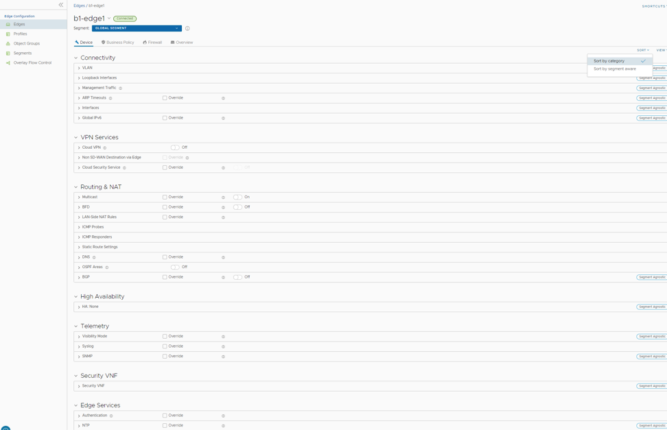

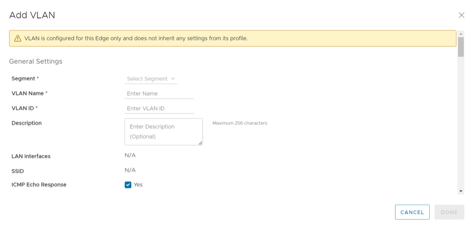
 Note: The system prevents overriding the Profile VLAN name and ID.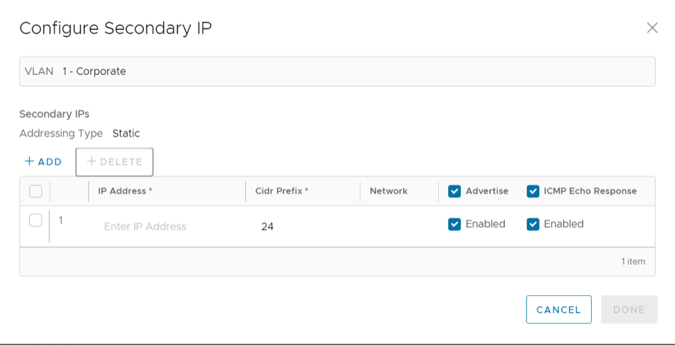
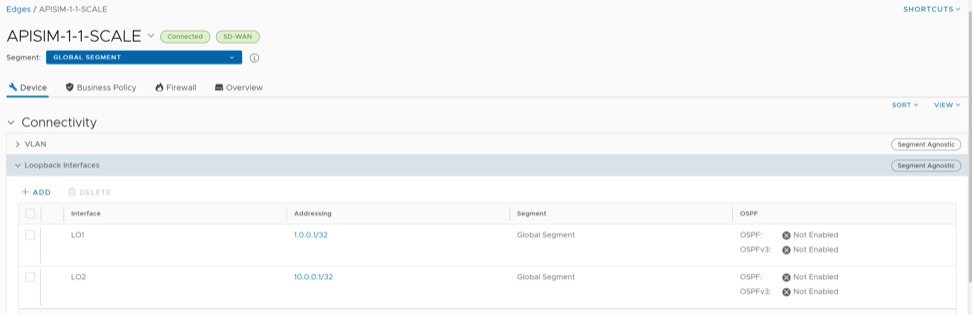
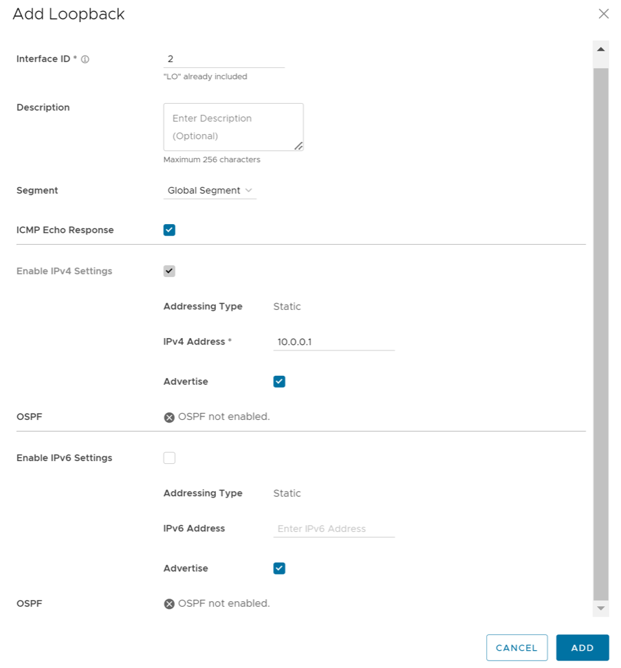
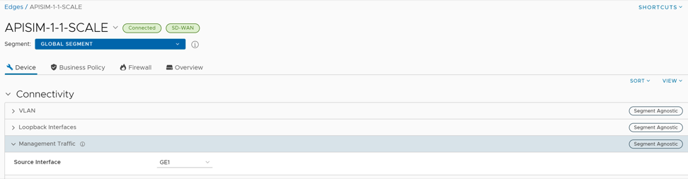
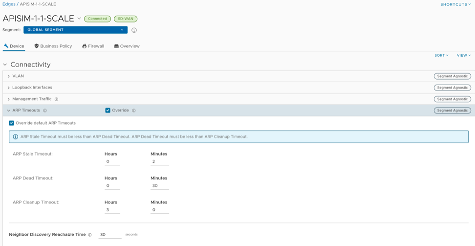
 Based on the Edge model, users can edit the settings for the following types of interfaces:
 The following RA parameters are selected by default. If required, users can turn them off.

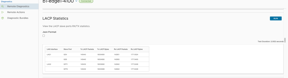
 Note:
Note:
 The above topology diagram illustrates enhanced HA, where a LAG is created on the WAN side of the network.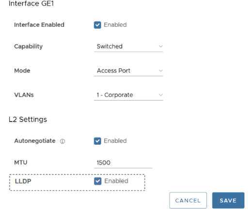
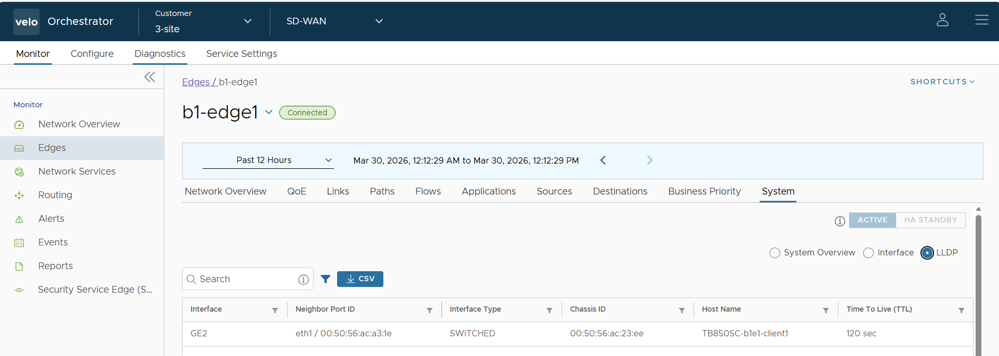
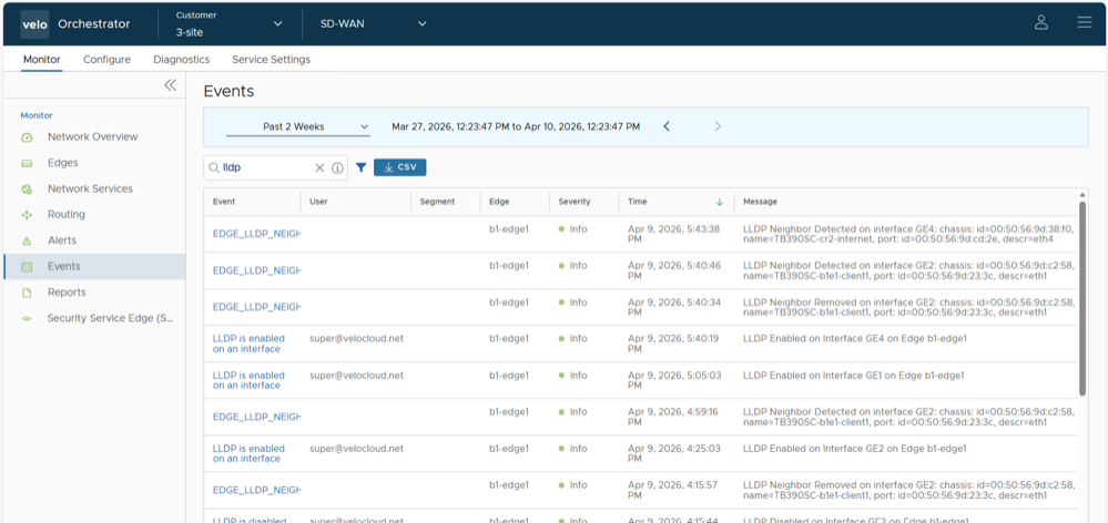

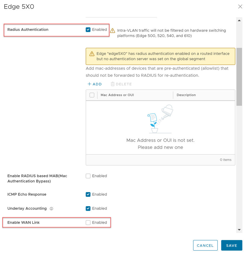
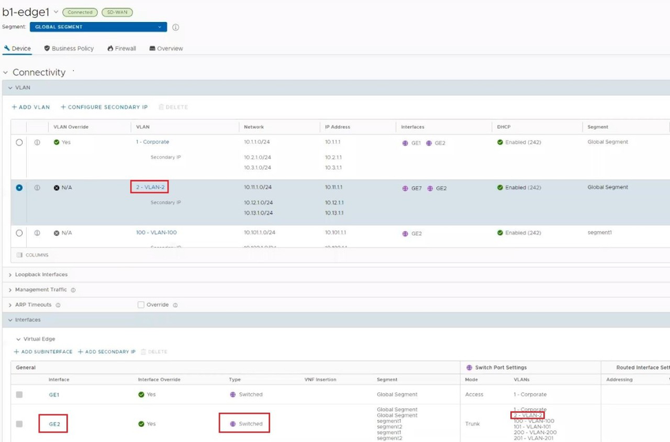
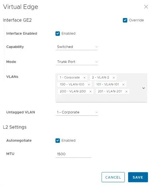
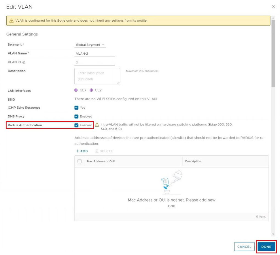
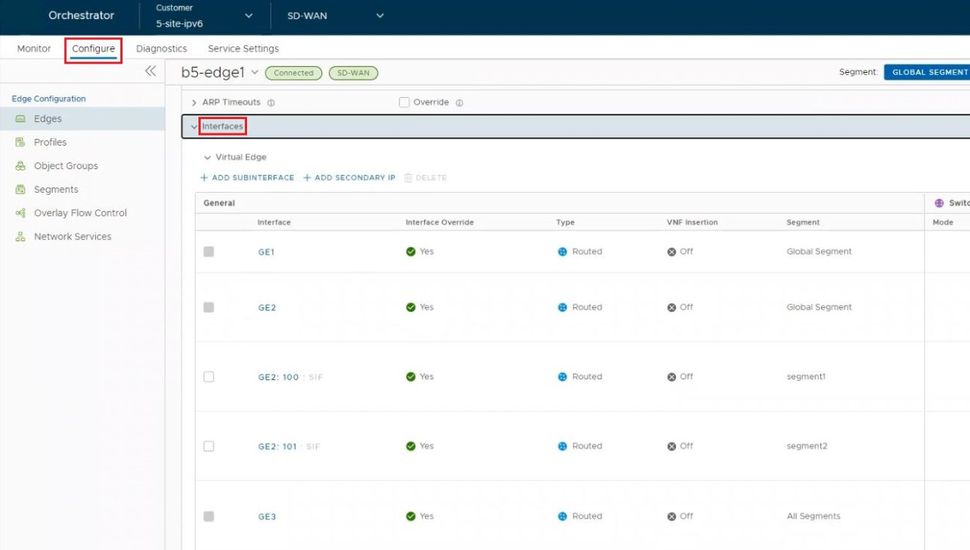


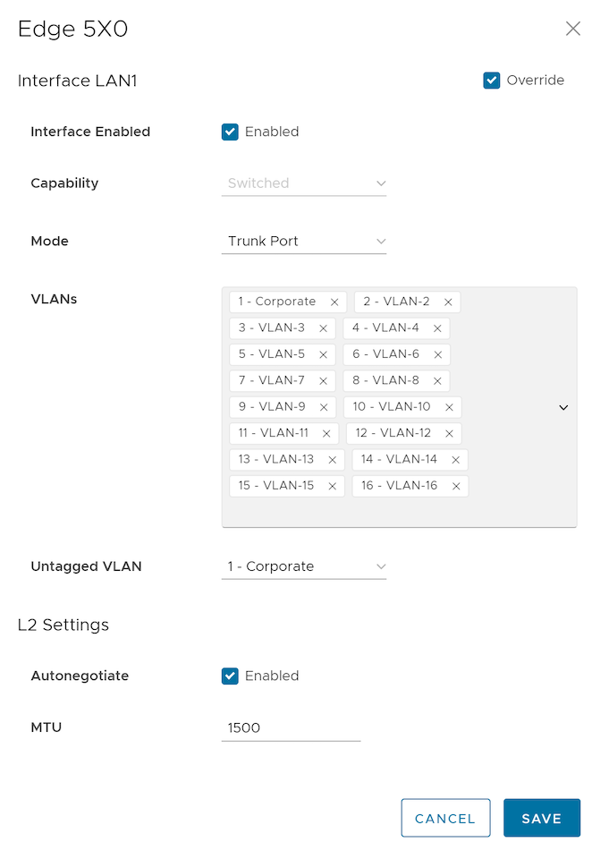
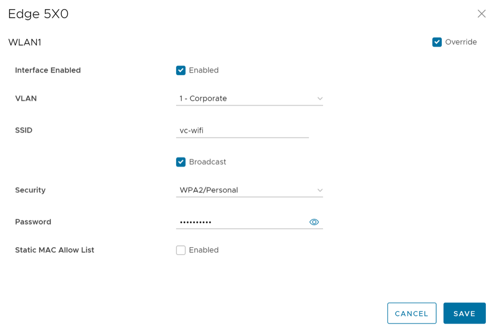
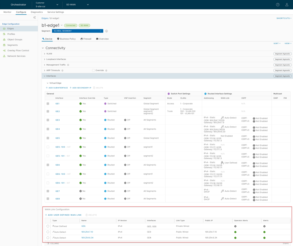


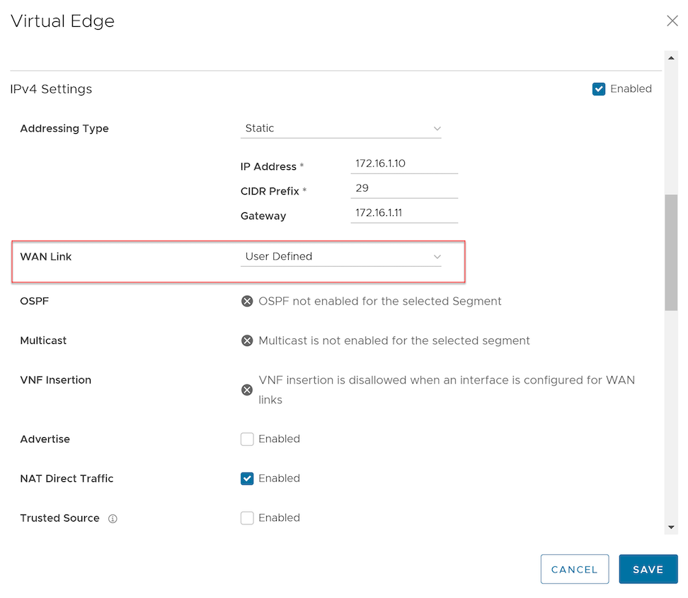

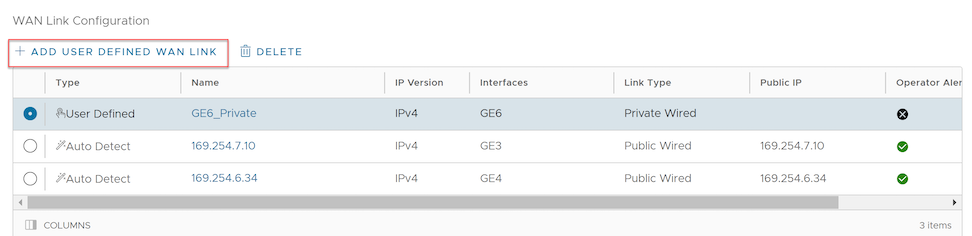


 Note:
Note: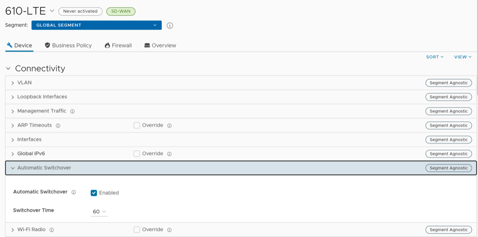

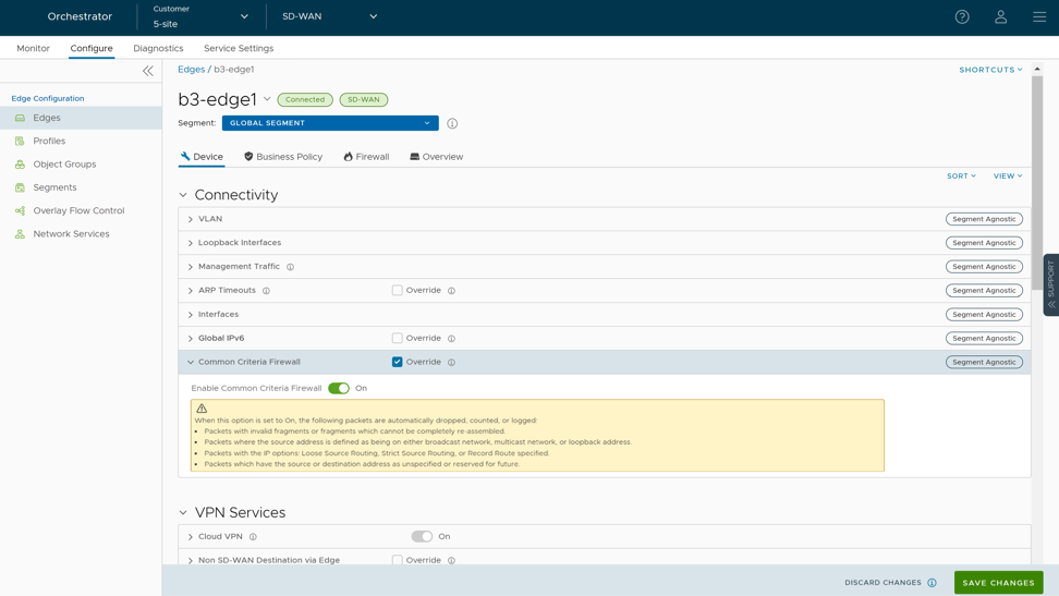

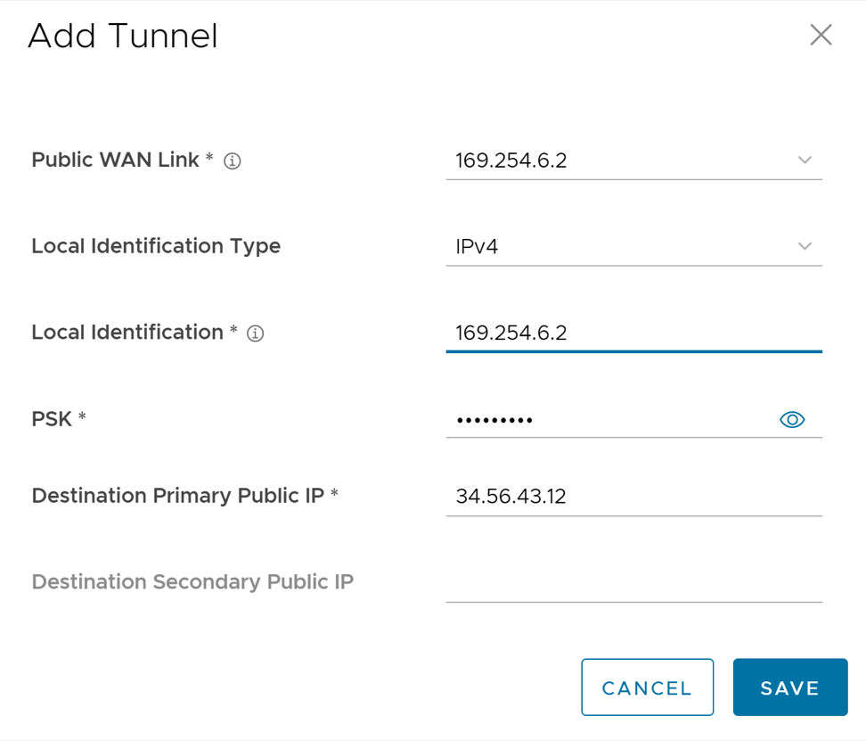
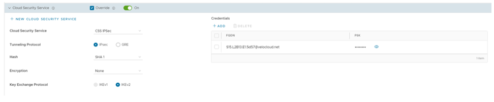

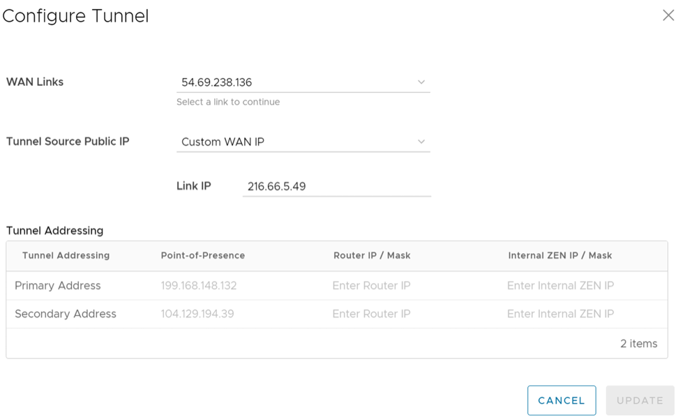


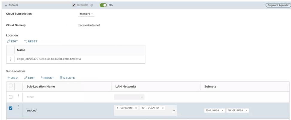 Note: After the user creates at least one Sub-location in the Orchestrator, an “Other” Sub-location is automatically created on the Zscaler side, and it appears in the Orchestrator UI. The user can also configure the “Other” Sub-location’s Gateway options by selecting the Edit button under Gateway Options in the Sub-Locations table. For additional information, see the "Configure Zscaler Gateway Options and Bandwidth Control" section.