Note: Hot-swap or reorient fans within one minute to prevent the switch from overheating and shutting down.
Ensure that the module you replace matches those already installed in the switch.
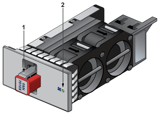
Note: The following figure shows a representative fan module that could differ from the one used in the switch.
Figure 1. Hot-swappable Fan Module
1
Release
2
Fan status LED
Considerations
The fan module is hot-swappable and can be reoriented for airflow direction. DCS-7010TX-48C-DC-RV3-F and DCS-7010TX-48C-DC-RV3A-F SKUs support only the -F orientation.
The switch will shut down if the fan module is disconnected for more than a minute.
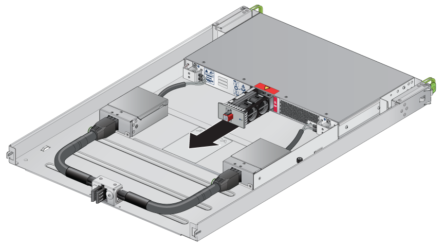
Perform the following steps to remove or replace the fan from a switch.
Ground yourself with an ESD wrist strap.
While squeezing the fan module release handle, pull the fan module out of the switch.
Note: The bottom clearance for squeezing the release handle is limited by the tray.
Installing a Fan Module
Perform the following steps to install a fan module in a switch.
Remove the replacement fan from its packaging.
Make space for installing the new fan module by removing the existing one (Removing a Fan Module).
Note: For DCS-7010TX-48C-DC-RV3-F and DCS-7010TX-48C-DC-RV3A-F SKUs, you will need a minimum of 2OU clearance above the installed switch to access the fan. Otherwise, remove the switch assembly from the rack for fan replacement (Figure 4 - Minimum Clearance for Hot-swapping Fan).
Slide the new fan module into the switch until the module is fully seated and the release lever snaps into place.
Note: For DCS-7010TX-48C-DC-RV3-F and DCS-7010TX-48C-DC-RV3A-F SKUs, ensure that the red label on the switch chassis next to the fan is visible (Figure 4 -DCS-7010TX-48-DC and DCS-7010TX-48C-DC).
Verify that the fan module is working normally.
Note: The fan module status LED should be a steady green for normal operation.