Rack Mounting the Switch
The rack mounting procedure is identical for all switches covered by this guide.
Les procédure de montage du bâti est identique pour tous les commutateurs visés par ce guide.
- Two-Post or Four-Post Rack Mountprovides instructions for mounting the switch in a two-post or four-post rack.
After completing the instructions for your rack type, proceed to Cabling the Switch.
Two-Post or Four-Post Rack Mount
The switch can be installed in a two-post or four-post rack. The installation process is identical because the switch attaches to only two posts of a rack.
To mount the switch in a rack, assemble the mounting brackets to the chassis, then attach the brackets to the rack posts. Rack mount accessory kits include the following parts:
-
Two mounting brackets
- Six M4x5 flat-head Phillips screws.
The following figure displays proper bracket placement for rack mount.

Attaching Mounting Brackets to the Chassis
This procedure attaches mounting brackets to the switch chassis.
- Attach the brackets with two M4x5 flat-head Philips screws, as shown in the following figure.
Figure 2. Attaching Mounting Brackets 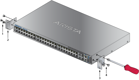
Inserting the Switch into the Rack
This procedure attaches the switch to the rack.
- Attach the bracket flanges to the rack posts.
Figure 3. Inserting Switch into the Rack 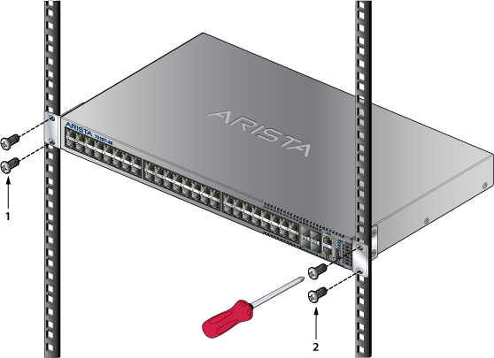
After completing the rack mount, proceed to Cabling the Switch.
DC-powered Rack Mount
There are ordering options for the switch that enable mounting in DC-powered racks such as ORv3 and its variants.
The following sections describe mounting the appropriate switch SKU in the relevant DC-powered rack. In all cases, installation requires mounting rails to be attached to the rack followed by inserting and securing the switch assembly to the rack.
ORv3 Rack Mount
The following figure shows the DCS-7010TX-48C-DC-RV3-F designed to be mounted in ORv3 racks.
| 1 | Hole (for latching) | 3 | Shelf (for switch assembly) | 5 | Hole (for latching) |
| 2 | L-shaped, IT-support bracket | 4 | L-shaped, IT-support bracket |
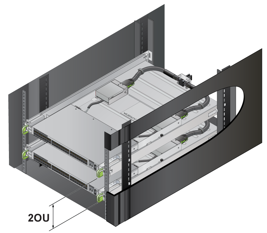
Racking the Switch Assembly (ORv3 Rack)
Perform the following tasks to mount the switch assembly into an ORv3 rack.
- Attach the L-shaped, IT-support bracket (not included with switch assembly) to the rack posts where the switch assembly will be mounted .
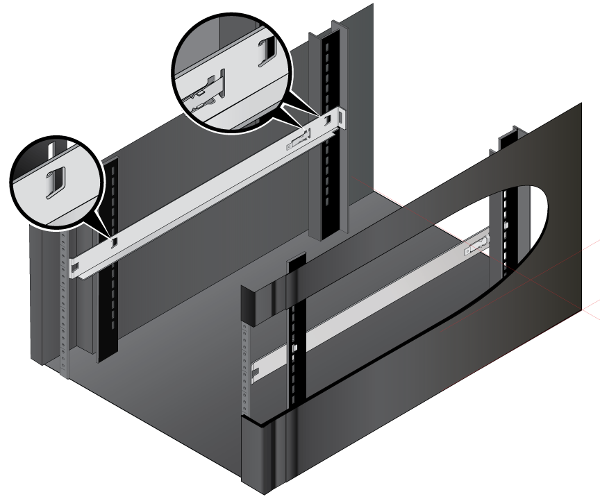
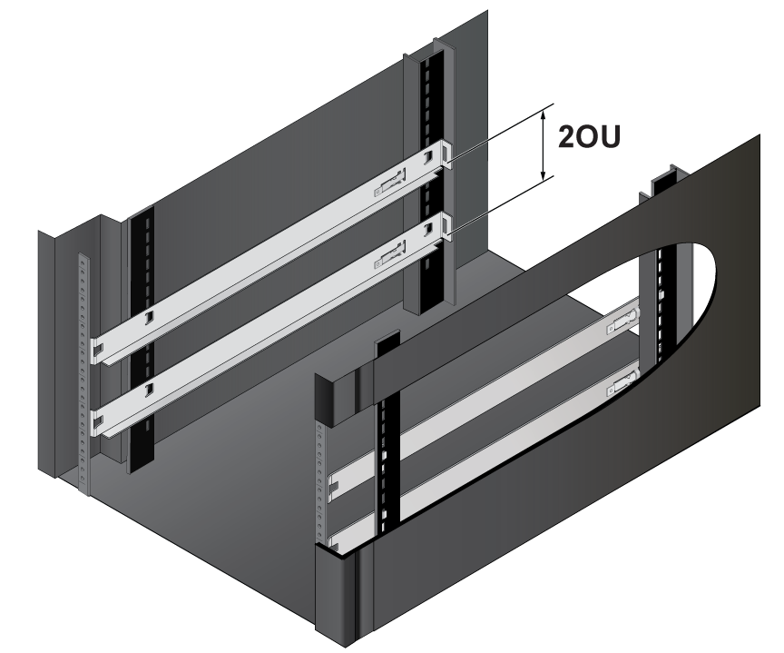
Note: Install the IT-support brackets at the same level to ensure that the switch assembly will be horizontal when racked. The IT-support brackets should snap into place on the supports. - If you are installing multiple switches, maintain a minimum of 2OU separation between them to provide space for servicing the hot-swappable fan.
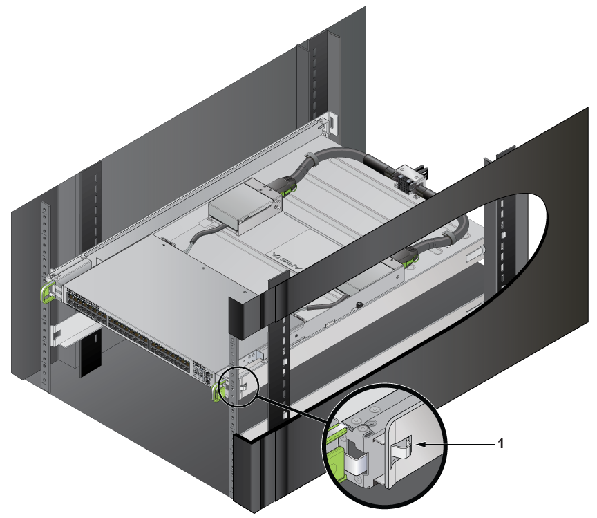
- Slide the switch assembly onto the shelf formed by the IT-support brackets.
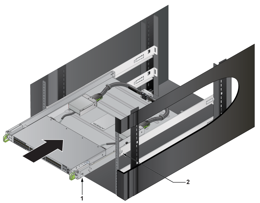
1 Latch 2 Hole for latching - Ensure that both the front latches are secured.
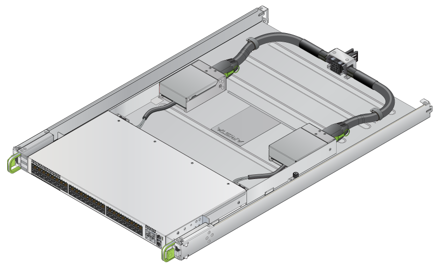
MGX or Similar Rack Mount
The following figure shows the DCS-7010TX-48C-DC-RV3A-F designed to be mounted in MGX or similar racks that accommodate products designed for 19" racks. Rack rails are attached to the sides of the switch assembly when shipped.
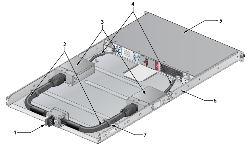
| 1 | Power connector (rack) | 4 | Power cables to switch | 7 | Cable management tie |
| 2 | Power cables to PEMs | 5 | Switch | ||
| 3 | Power Entry Modules (PEMs) | 6 | Rack rails |
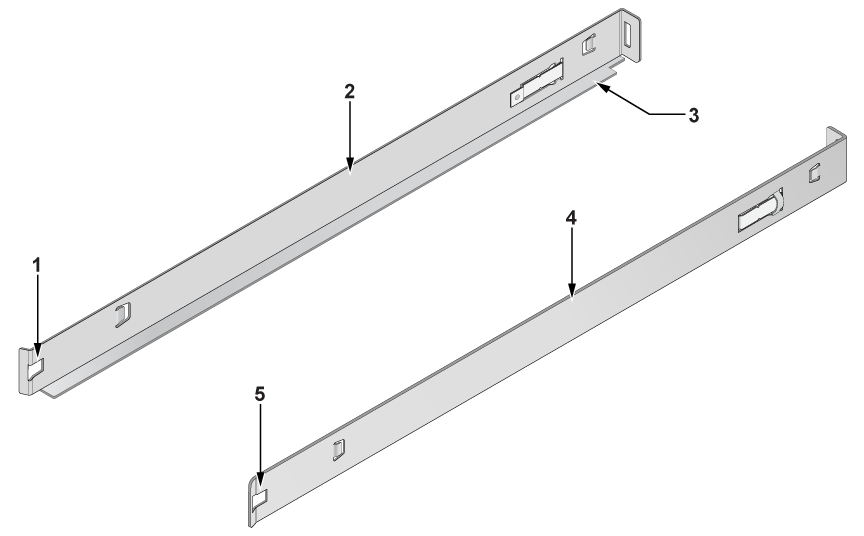
Racking the Switch Assembly (MGX or Similar)
Perform the following tasks to atttach the mounting rails to the switch assembly.
- Loosen the rack rails from the switch assembly sides.
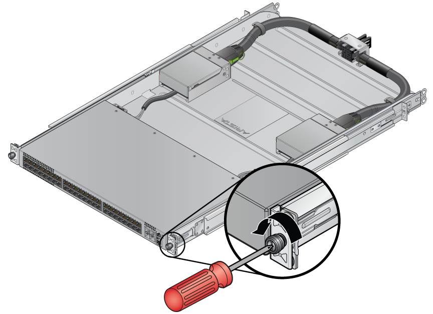
- Remove the rails.
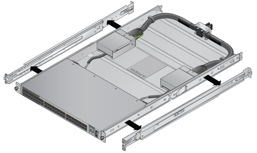
- Secure the rails to the rack.
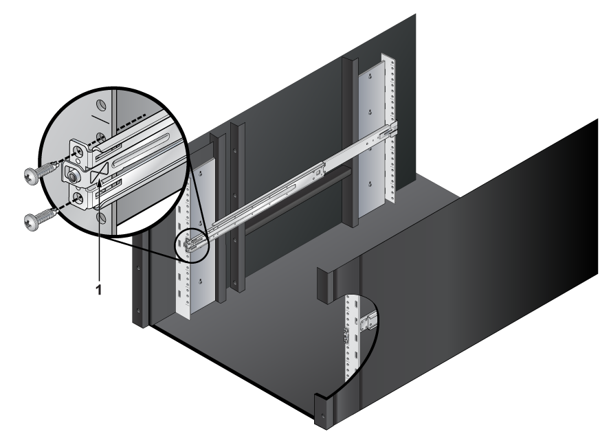
1 Rail identifier symbol - Slide the switch assembly into the rack and secure it using the thumb screws.
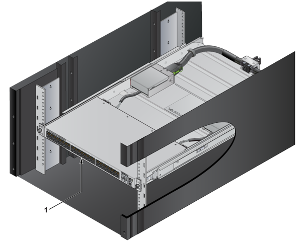
1 Switch
Flat Surface Placement
The switch is prepared for flat surface placement by attaching four rubber pads on the bottom of the chassis to prevent the switch from sliding on the table and to protect the surface of the table.
The installation kit provides the following flat surface placement parts.
- Four rubber switch pads

| 1 | Sheet with four rubber pads |
To prepare the switch for placement on a flat surface, peel the four rubber pads from the master sheet and attach one in each indentation near each corner on the bottom of the switch.
The following figure displays the rubber pad placement on the bottom of the switch.
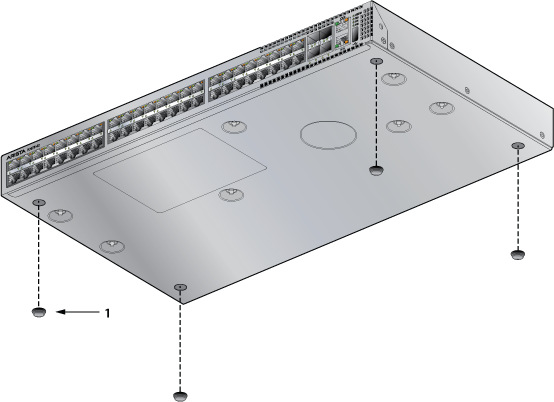
| 1 | Rubber pad |