Status Indicators
This section discusses the following topics:
Front Indicators
System and port status LED indicators are located on the front of the switches.
Switch Indicators
Front panel LEDs are located on the right side of the chassis, and the display system, fan, and power supply status. Front Panel displays the front panels of all switches covered by this guide.
Figure 1 - System Status Indicators displays the front panel LEDs.
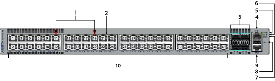
| 1 | Port numbers | 5 | System status LED | 9 | Console serial port |
| 2 | Port status LED | 6 | Fan tray status LED | 10 | RJ-45 ports |
| 3 | SFP25 Ports | 7 | Power supply status LED | ||
| 4 | Ethernet management port | 8 | USB port |
| LED Name | LED State | Device Status |
|---|---|---|
| System Status | Blinking Green | System powering up. |
| Green | All power supplies and fans are operating normally. | |
| Blue | The locator function is active. | |
| Red | A power supply or fan is missing or in a failed state. | |
| Fan Status | Green | All fans are operating normally. |
| Red | One or more fans have not been inserted or have failed. | |
| Power Supply Status | Off | Power supply is not inserted or is not powered. |
| Green | Power supply operating normally. | |
| Red | Power supply has failed. |
Port Indicators
Port LEDs, near their corresponding ports, provide a link and operational status. The following figure displays the Port LED location on a representative switch.
| 1 | Port numbers | 5 | System status LED | 9 | Console serial port |
| 2 | Port status LED | 6 | Fan tray status LED | 10 | RJ-45 ports |
| 3 | SFP25 Ports | 7 | Power supply status LED | ||
| 4 | Ethernet management port | 8 | USB port |
Table 2 - Port LED States provide status conditions that correspond to port LED states. Port LED behavior for QSFP+ and SFP+ ports is consistent.
| LED State | Status |
|---|---|
| Off | Port link is down. |
| Green | Port link is up. |
| Yellow | Port is software disabled. |
| Flashing Yellow | Port failed diagnostics. |
Rear Status Indicators
The fan module contains an LED that reports the module status. Fan Status LEDs are on the fan modules and are visible through the cover.
The fan module orientation determines the direction of air flowing through the switch. The fan module, when inserted, covers one of the two airflow labels with the visible label indicating the current airflow direction.
The switch shuts down when the fan module is removed for more than one minute.
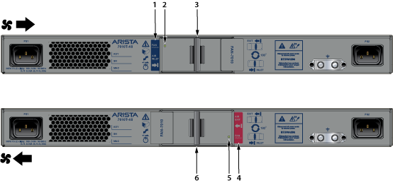
| 1 | Airflow direction indicator label | 3 | Fan module handle and release | 5 | Fan status LED |
| 2 | Fan status LED | 4 | Airflow direction indicator label | 6 | Fan module handle and release |
The following table provides status conditions that correspond to fan status LED states.
| LED State | Status |
|---|---|
| Off | The fan module is inserted but not receiving power – it may not be properly seated. |
| Green | The fan is operating normally. |
| Red | The fan has failed. |
You can narrow down the error condition by logging in to the switch to view the specific device state. Refer to the Arista User Manual’s Switch Environment Control chapter under Viewing Environment Status for further information on the show environment commands.