Configuration for Route-Based NSD Via Gateway
Route-Based NSD Via Gateway to VMware Cloud AWS Gateway Overview
The figure below illustrates the Integration of Arista VeloCloud SD-WAN and VMware Cloud on AWS, which uses IPsec connectivity between the Arista VeloCloud Gateway and the VMware Cloud Gateway.
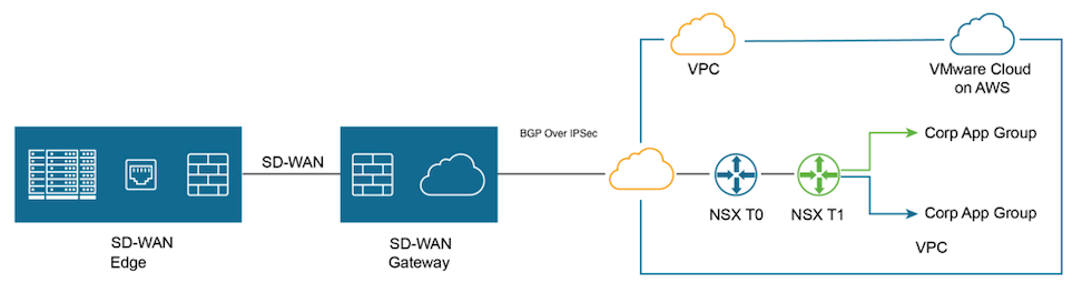
Perform the following steps to achieve connectivity between an SD-WAN Gateway and a VMware Cloud Gateway.
- Find Public IP used for VPN connectivity by selecting the Networking and Security tab. The VPN Public IP displays below the Overview pane.
Figure 2. Overview Pane 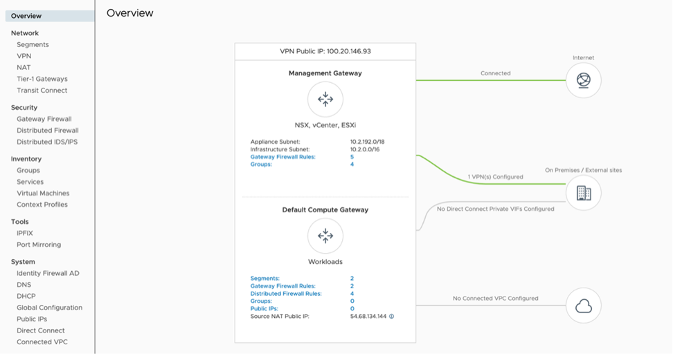
- Log into the SD-WAN Orchestrator and verify that the Edges are displayed (a green status icon will be displayed next to them).
Figure 3. Network Overview 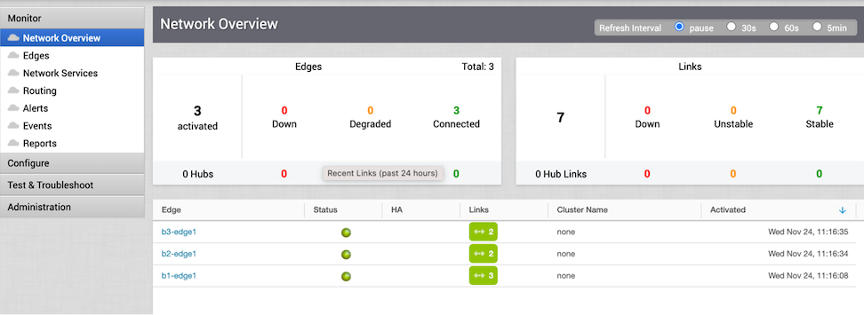
- Go to the Configure tab and select Network Services. Under Non SD-WAN Destination via Gateway, select the New button.
Figure 4. Non SD-WAN Destinations via Gateway 
- Provide a name for the Non SD-WAN Destination via Gateway. Select the type, in this case, Generic IKEv2 Router (Route Based VPN), and Enter the Public IP from the VMC obtained in Step 2, and select Next.
Figure 5. New Non SD-WAN Destination via Gateway 
- Select Advanced and complete the following steps:
- Select Save Changes.
Figure 6. VMC on AWS 
- Select Save Changes.
- Select View IKE/IPSec Template and copy the information into a text file, and then close the window.
Figure 7. IKE IPSec Configuration 
- On the left pane, select .
Figure 8. Configuration Profiles 
- Under the correct Profile, perform the following. steps:
- Select the Save Changes button at the top of the screen.
Figure 9. Quick Start Profile 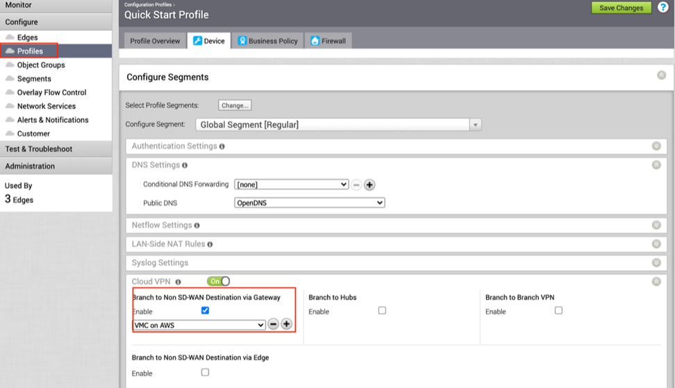
- Select the Save Changes button at the top of the screen.
- Navigate to the Network service page, select the BGP button in NSD via Gateway service area.
Figure 10. Non SD-WAN Destinations via Gateway 
- Configure BGP parameters by performing the following steps:
- Local IP – 169.254.32.1
Note: It is recommended to use a /30 CIDR from 169.254.0.0/16 subnet excluding following VMC reserved addresses- 169.254.0.0-169.254.31.255, 169.254.101.0-169.254.101.3.
Figure 11. BGP Enable 
The tunnel should be ready on the SD-WAN Orchestrator with BGP over IPSec.
- Local IP – 169.254.32.1
- Go to Networking and Security and select the VPN tab. In the VPN area, select Route Based VPN, and select Add VPN.
Figure 12. VMC-SD-WAN 
- Provide a name for the Route Based VPN and configure the following:
- Select Save.
Figure 13. VPN Route Based 
- Select Save.
- Once the configuration is complete, the tunnel is automatically activated and will proceed to negotiate the IKE Phase 1 and Phase 2 parameters with the peer, which is the VeloCloud Gateway.
Figure 14. VPN 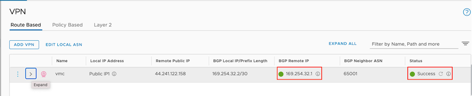
- Once the tunnel displays (green), verify that the NSD via Gateway tunnel/BGP status in the SD-WAN Orchestrator (go to ).
Figure 15. Network Services 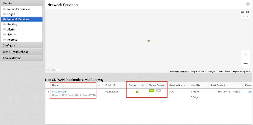
- Start a ping from a client connected at each end towards the opposite client, and verify ping reachability. The tunnel configuration has been completed and verified.
Figure 16. BGP Gateway Neighbor State 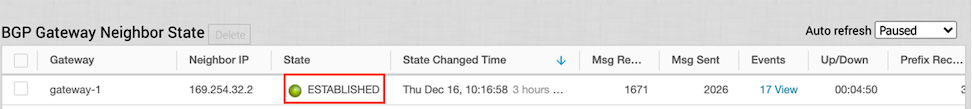
Figure 17. Ping Verification 