IPsec Support
The AWE-7200R and CloudEOS router provide robust support for using IPsec to establish and maintain IPsec tunnels for secure or encrypted communications between virtual router peer instances and virtual peer instances to non-virtual routers.
- Secure the communications between AWE-7200R and CloudEOS router instances.
- Secure the communications between AWE-7200R and CloudEOS router instances and third-party virtual router instances.
Note: See the AWE-7200R and CloudEOS router Release Notes for the latest information on the types of virtual routers that can share IPsec tunnels with AWE-7200R and CloudEOS router.
- Supported Tunnel Types
The AWE-7200R and CloudEOS router support the use of two basic types of IPsec tunnels. The encapsulation mode determines the tunnel types.
- Requirements when Behind a NAT
The AWE-7200R and CloudEOS router support using NAT-Traversal to communicate with the remote peer virtual router. To ensure successful tunnel configuration between the AWE-7200R and CloudEOS router and peer router, make sure that the AWE-7200R and CloudEOS router tunnel configuration meet the requirements for using NAT.
Note: DCS-7020SRG does not support NAT-Traversal for IPsec. - Using IPsec on CloudEOS and AWE-7200R and CloudEOS Instances
The AWE-7200R and CloudEOS router enables you to establish and maintain GRE-over-IPsec and VTI IPsec tunnels for secure or encrypted communications between peer AWE-7200R and CloudEOS router instances.
- CloudEOS IPsec Connectivity to Azure Virtual Network Gateway
Supported Tunnel Types
The AWE-7200R and CloudEOS router supports the use of two basic types of IPsec tunnels. The encapsulation mode determines the tunnel types.
CloudEOS supports the following tunnel types:- In GRE-over-IPsec encapsulation mode, the application payload first encapsulates within a GRE packet. IPsec then encrypts the GRE packet and then encapsulates the packet using the IPsec header.
- Select this encapsulation type by specifying tunnel mode gre for the tunnel interface and apply to the IPsec profile. This ensures that encrypted packets forward to the interface.
- When using GRE-over-IPsec encapsulation mode, CloudEOS supports both IPsec mode options either transport or tunnel .
- In VTI encapsulation mode, the IPsec header directly encapsulates and encrypts the application payload.
- Select this encapsulation type by specifying tunnel mode ipsec for the tunnel interface with the IPsec profile. This ensures that the encrypted packets forward to the interface.
- When using VTI encapsulation mode, set the IPsec mode to tunnel . The transport option under the IPsec mode has no effect.
Requirements when Behind a NAT
The AWE-7200R and CloudEOS router supports using NAT-Traversal to communicate with the remote peer behind a NAT. Configure the tunnel source with the outgoing interface IP address on the router.
Flow Parallelization
Enable the IPsec flow parallelization feature to achieve high throughput over an IPsec connection. Multiple cores use parallel IPsec encryption and decryption processing when enabled. To enable this feature, include the flow parallelization encapsulation udp command in the IPsec profile configuration.
- Under the tunnel IPsec profile, use the flow parallelization encapsulation udp command to enable the feature.
- Shut down the tunnel on the tunnel interface.
- Bring the tunnel back up on the tunnel interface. After it becomes active, this enables the feature.
Using IPsec on AWE-7200R and CloudEOS Router Instances
IPSec Topology
Use the AWE-7200R and CloudEOS Router to establish and maintain IPsec tunnels between peer AWE-7200R and CloudEOS Router instances in different topologies of varying complexity.
- Creating an IKE Policy to establish IKE with the peer.
- Specifying the encryption integrity protocols for the Security Association (SA) Policy.
- Apply IKE and SA policies to a profile.
- Apply the profile to a tunnel interface.
Configuring IPsec Tunnels on AWE-7200R and CloudEOS Router Instances
Use this procedure to configure GRE-over-IPsec or VTI IPsec tunnels on a peer AWE-7200R and a CloudEOS router instances.
The procedure provides all the steps required to set up either GRE-over-IPsec or VTI IPsec tunnels. Some steps may be identical for both tunnel types . Step 7 selects the tunnel type.
Procedure
Complete the following steps to configure GRE-over-IPsec or VTI IPsec tunnels on AWE-7200R and CloudEOS router instances.
Examples of Running Configurations for GRE-over-IPsec Tunnels
The following examples display the running configurations for two AWE-7200R and CloudEOS router instances, an AWE-7200R and CloudEOS Router1, and an AWE-7200R and CloudEOS Router2. The instances have the tunnel endpoints of a GRE-over-IPsec tunnel.
Running Configuration for AWE-7200R and CloudEOS Router1
ip security ike policy ikebranch1 integrity sha256 dh-group 15 ! sa policy sabranch1 sa lifetime 2 pfs dh-group 14 ! profile hq mode tunnel ike-policy ikebranch1 sa-policy sabranch1 connection add shared-key keyAristaHq dpd 10 50 clear ! interface Tunnel1 mtu 1404 ip address 1.0.3.1/24 tunnel mode gre tunnel source 1.0.0.1 tunnel destination 1.0.0.2 tunnel ipsec profile hq ! interface Ethernet1 no routerport ip address 1.0.0.1/24 !
Running Configuration for AWE-7200R and CloudEOS Router2
ip security ike policy ikebranch1 integrity sha256 dh-group 15 ! ike policy ikebranch2 dh-group 15 version 1 local-id 200.0.0.1 ! ike policy ikedefault ! sa policy sabranch1 sa lifetime 2 pfs dh-group 14 ! profile hq mode tunnel ike-policy ikebranch1 sa-policy sabranch1 connection start shared-key keyAristaHq dpd 10 50 clear ! interface Tunnel1 mtu 1404 ip address 1.0.3.2/24 tunnel mode gre tunnel source 1.0.0.2 tunnel destination 1.0.0.1 tunnel ipsec profile hq ! interface Ethernet2 no routerport ip address 1.0.0.2/24 !
Examples of Running-Configurations for VTI IPsec Tunnels
The following examples display the running configurations for two AWE-7200R and CloudEOS router instances, an AWE-7200R and CloudEOS Router1, and an AWE-7200R and CloudEOS Router 2. The instances have the tunnel endpoints of a VTI IPsec tunnel.
Running Configuration for AWE-7200R and CloudEOS Router 1
ip security ike policy ikebranch1 integrity sha256 dh-group 15 ! sa policy sabranch1 sa lifetime 2 pfs dh-group 14 ! profile hq mode tunnel ike-policy ikebranch1 sa-policy sabranch1 connection add shared-key keyAristaHq dpd 10 50 clear ! interface Ethernet1 no routerport ip address 1.0.0.1/24 ! interface Management1 ip address dhcp ! interface Tunnel1 mtu 1404 ip address 1.0.3.1/24 tunnel mode ipsec tunnel source 1.0.0.1 tunnel destination 1.0.0.2 tunnel ipsec profile hq !
Running Configuration for AWE-7200R and CloudEOS Router 2
ip security ike policy ikebranch1 integrity sha256 dh-group 15 ! ike policy ikebranch2 dh-group 15 version 1 local-id 200.0.0.1 ! ike policy ikedefault ! sa policy sabranch1 sa lifetime 2 pfs dh-group 14 ! profile hq mode tunnel ike-policy ikebranch1 sa-policy sabranch1 connection start shared-key keyAristaHq dpd 10 50 clear ! interface Ethernet2 no routerport ip address 1.0.0.2/24 ! interface Management1 ip address dhcp ! interface Tunnel1 mtu 1404 ip address 1.0.3.2/24 tunnel mode ipsec tunnel source 1.0.0.2 tunnel destination 1.0.0.1 tunnel ipsec profile hq !
Using IPsec on AWE-7200R and CloudEOS and Third Party Devices
The AWE-7200R and CloudEOS Router establishes and maintains IPsec tunnels for secure or encrypted communications between CloudEOS and router instances and third-party devices peer router instances.
- Creating an IKE Policy to establish IKE with the peer.
- Specifying the encryption and integrity protocols for the Security Association (SA) Policy.
- Apply IKE and SA policies to a given profile.
- Apply the profile to a tunnel interface.
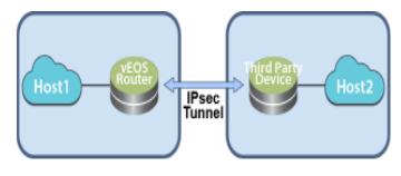
Topology
Use the Router to establish and maintain IPsec tunnels between router instances and third-party router instances in different topologies of varying complexity.
The following diagram represents a basic IPsec tunnel configuration where a router instance and a third-party router instance are connected using an IPsec tunnel.
Interoperability Support
The AWE-7200R and CloudEOS Router establishes and maintains IPsec tunnels for the secure or encrypted communications between AWE-7200R and CloudEOS Router instances and third-party device peer router instances.
- Palo Alto Firewall VM
- Set up these IPsec tunnels between AWE-7200R and CloudEOS Router instances, and Palo Alto firewall VM router instances.
- VTI IPsec
- VTI IPsec
- Set up these IPsec tunnels between AWE-7200R and CloudEOS Router instances, and Palo Alto firewall VM router instances.
- CSR
- Set up these IPsec tunnels between AWE-7200R and CloudEOS Router instances, and CSR router instances.
- GRE-over-IPsec
- VTI IPsec
- Set up these IPsec tunnels between AWE-7200R and CloudEOS Router instances, and CSR router instances.
- AWS VPN Specific Cloud
- Set up these IPsec tunnels between AWE-7200R and CloudEOS Router instances, and AWS VPN Specific Cloud router instances.
- VTI IPsec
- VTI IPsec
- Set up these IPsec tunnels between AWE-7200R and CloudEOS Router instances, and AWS VPN Specific Cloud router instances.
- vSRX
- Set up these t IPsec tunnels between AWE-7200R and CloudEOS Router instances, and vSRX router instances.
- VTI IPsec
- VTI IPsec
- Set up these t IPsec tunnels between AWE-7200R and CloudEOS Router instances, and vSRX router instances.
- CloudEOS and vEOS Routers and Palo Alto firewall AM
- CloudEOS and vEOS Routers and CSR
- CloudEOS and vEOS and AWS Specific Cloud
AWE-7200R and CloudEOS Router and Palo Alto Firewall VM
AWE-7200R and CloudEOS Router Configuration
Use this procedure to configure GRE-over-IPsec tunnels on a AWE-7200R and CloudEOS Router instance. Once the procedure is complete, configure the other tunnel end-point on the third-party peer router.
Procedure
Complete the following steps to configure the AWE-7200R and CloudEOS Router instance to share a GRE-over IPsec tunnel.
router(config)#ip security router(config-ipsec)#ike policy ike-peerRtr router(config-ipsec-ike)#version 1
Configuring VTI IPsec Tunnels
The AWE-7200R and CloudEOS Router can configure VTI IPsec tunnels between a AWE-7200R and CloudEOS Router instance and a third-party peer router instance (such as a Palo Alto firewall VM). First, complete the set up of the tunnel on the AWE-7200R and CloudEOS Router instance, then set up the other end of the tunnel on the third-party peer router instance.
Palo Alto Firewall VM Configuration
Use this configuration when pairing a Palo Alto firewall VM instance and AWE-7200R and CloudEOS Router instance as tunnel endpoints of an IPsec VTI IPsec tunnel.
Supported Tunnel Types
Set up IPsec VTI tunnels using the Palo Alto firewall VM as a peer router instance with a AWE-7200R and CloudEOS Router instance. IPsec GRE-over-IPsec tunnels using this combination of router instances as peers is not permitted.
Configuration Guidelines
- IP address settings.
Configure the first interface to be configured (typically named eth0 ), as the management interface. Use the public IP address on this interface to open the GUI of the Palo Alto firewall VM.
Management interface.
Use this interface only for control plane traffic.
- Management profile.
When configuring the profile, select all protocols allowed on the management interface.
Procedure
AWE-7200R and CloudEOS, Palo Alto Firewall VM Pairing (VTI IPsec Tunnel)
The following example shows a VTI IPsec tunnel between a AWE-7200R and CloudEOS Router instance and a third-party Palo Alto firewall VM router instance.
Running Configuration for AWE-7200R and CloudEOS
ip security
ike policy ikebranch1
integrity sha256
dh-group 15
!
sa policy sabranch1
sa lifetime 2
pfs dh-group 14
!
profile hq
ike-policy ikebranch1
sa-policy sabranch1
connection add
shared-key keyAristaHq
dpd 10 50 clear
!
interface Ethernet1
no routerport
ip address 1.0.0.1/24
!
interface Management1
ip address dhcp
!
interface Tunnel1
mtu 1404
ip address 1.0.3.1/24
tunnel mode ipsec
tunnel source 1.0.0.1
tunnel destination 1.0.0.2
tunnel ipsec profile hq
!
Running Configuration on Palo Alto Firewall VM
"ike": {
"crypto-profiles": {
"ike-crypto-profiles": [
{
"@name": "veos12-IKE-Phase1",
"hash": {
"member": "sha512"
},
"dh-group": {
"member": "group20"
},
"encryption": {
"member": "aes-256-cbc"
},
"lifetime": {
"hours": "8"
}
}
]
"ipsec-crypto-profiles": [
{
"@name": "veos12-IPSEC-Phase2",
"esp": {
"authentication": {
"member": "sha256"
},
"encryption": {
"member": "aes-256-cbc"
}
},
"lifetime": {
"hours": "2"
},
"dh-group": "group20"
}
"gateway": {
"entry": {
"@name": "veos12-IKE-Gateway",
"authentication": {
"pre-shared-key": {
"key": "-AQ==ocHnGzxJ4JVLomPyHuZNlg84S7I=BCiu0HIvFeFOSQOx/gmhNQ=="
}
},
"protocol": {
"ikev1": {
"dpd": {
"enable": "yes",
"interval": "100",
"retry": "100"
},
"ike-crypto-profile": "veos12-IKE-Phase1"
},
"ikev2": {
"dpd": {
"enable": "yes"
},
"ike-crypto-profile": "veos12-IKE-Phase1"
},
"version": "ikev2-preferred"
}
"tunnel": {
"ipsec": {
"entry": {
"@name": "veos12-IPSEC-Tunnel",
"auto-key": {
"ike-gateway": {
"entry": {
"@name": "veos12-IKE-Gateway"
}
},
"ipsec-crypto-profile": "veos12-IPSEC-Phase2"
},
"tunnel-monitor": {
"enable": "yes",
"destination-ip": "1.0.3.1",
"tunnel-monitor-profile": "Test"
},
"tunnel-interface": "tunnel.1",
"disabled": "no"
}
}
}
}
AWE-7200R and CloudEOS Router Configuration
Use this procedure to configure VTI IPsec tunnels on an Arista router instance. Complete the procedure, then configure the other tunnel endpoint on the third-party peer router.
Procedure
Complete the following steps to configure a AWE-7200R and CloudEOS Router instance to share a VTI IPsec tunnel.
To use IKE version 1, complete the section below, then continue with the steps below. To use IKE version 2, the default version, start with Step 1 below.
router(config)#ip security router(config-ipsec)#ike policy ike-peerRtr router(config-ipsec-ike)#version 1
Configure the VTI IPsec tunnel on the peer router (see Palo Alto Firewall VM Configuration ).
CSR Router Show Commands
This section discusses the available CSR Router show commands and their example outputs.
View all Existing ISAKMP SAs
Use the show crypto isakmp sa command to view the ISAKMP SAs for all existing or current IPsec connections.
router# show crypto isakmp sa IPv4 Crypto ISAKMP SA dst src state conn-id status 1.0.0.1 1.0.0.2 QM_IDLE 1331 ACTIVE vrouter-ikev1-isakmp-profile IPv6 Crypto ISAKMP SA
View all Existing IPsec SAs
Use the show crypto ipsec sa command to view the IPsec SAs for all existing or current IPsec connections.
router# show crypto ipsec sa
interface: Tunnel0
Crypto map tag: Tunnel0-head-0, local addr 1.0.0.2
protected vrf: (none)
local ident (addr/mask/prot/port):
(1.0.0.2/255.255.255.255/47/0)
remote ident (addr/mask/prot/port):
(1.0.0.1/255.255.255.255/47/0)
current_peer 1.0.0.1 port 500
PERMIT, flags={origin_is_acl,}
#pkts encaps: 1, #pkts encrypt: 1, #pkts digest: 1f
#pkts decaps: 1, #pkts decrypt: 1, #pkts verify: 1
#pkts compressed: 0, #pkts decompressed: 0
#pkts not compressed: 0, #pkts compr. failed: 0
#pkts not decompressed: 0, #pkts decompress failed: 0
#send errors 0, #recv errors 0
local crypto endpt.: 1.0.0.2, remote crypto endpt.:
1.0.0.1
plaintext mtu 1438, path mtu 1500, ip mtu 1500, ip mtu idb
GigabitEthernet2
current outbound spi: 0xCB8FB740(3415193408)
PFS (Y/N): N, DH group: none
Dummy packet: Initializing
inbound esp sas:
spi: 0x36383677(909653623)
transform: esp-aes esp-sha-hmac ,
in use settings ={Tunnel, }
conn id: 5287, flow_id: CSR:3287, sibling_flags
FFFFFFFF80004048, crypto map: Tunnel0-head-0
sa timing: remaining key lifetime (k/sec): (4607999/3598)
IV size: 16 bytes
replay detection support: Y
Status: ACTIVE(ACTIVE)
inbound ah sas:
inbound pcp sas:
outbound esp sas:
spi: 0xCB8FB740(3415193408)
transform: esp-aes esp-sha-hmac ,
in use settings ={Tunnel, }
conn id: 5288, flow_id: CSR:3288, sibling_flags
FFFFFFFF80004048, crypto map: Tunnel0-head-0
sa timing: remaining key lifetime (k/sec): (4607999/3598)
IV size: 16 bytes
replay detection support : Y
Status: ACTIVE(ACTIVE)
outbound ah sas:
outbound pcp sas:
View Crypto (Encryption) Session Details
Use the show crypto session detail command to view details about the crypto session for all current IPsec connections.
router# show crypto session detail
Crypto session current status
Code: C - IKE Configuration mode, D - Dead Peer Detection
K - Keepalives, N - NAT-traversal, T - cTCP encapsulation
X - IKE Extended Authentication, F - IKE Fragmentation
R - IKE Auto Reconnect
Interface: Tunnel0
Profile: vrouter-ikev1-isakmp-profile
Uptime: 00:20:23
Session status: UP-ACTIVE
Peer: 1.0.0.1 port 500 fvrf: (none) ivrf: (none)
Phase1_id: 1.0.0.1
Desc: (none)
Session ID: 0
IKEv1 SA: local 1.0.0.2/500 remote 1.0.0.1/500 Active
Capabilities:(none) connid:1332 lifetime:07:39:35
IPSEC FLOW: permit 47 host 1.0.0.2 host 1.0.0.1
Active SAs: 2, origin: crypto map
Inbound: #pkts dec'ed 42 drop 0 life (KB/Sec)
4607997/2375
Outbound: #pkts enc'ed 44 drop 0 life (KB/Sec)
4607995/2375
View IKEv2 SAs
Use the show crypto ikev2 sa command to view summary information about all IKE version 2 SAs used by existing IPsec connections.
router# show crypto ikev2 sa IPv4 Crypto IKEv2 SA Tunnel-id Local Remote fvrf/ivrf Status 1 3.3.3.3/500 3.3.3.1/500 none/none READY Encr: AES-CBC, keysize: 128, PRF: sha256, Hash: SHA96, DH Grp:14, Auth sign: PSK, Auth verify: PSK Life/Active Time: 86400/5349 sec IPv6 Crypto IKEv2 SA
View IKEv2 SA Details
Use the show crypto ikev2 sa detailed command to view details about all IKE version 2 SAs used by existing IPsec connections.
router# show crypto ikev2 sa detailed
IPv4 Crypto IKEv2 SA
Tunnel-id Local Remote fvrf/ivrf Status
1 3.3.3.3/500 3.3.3.1/500 none/none READY
Encr: AES-CBC, keysize: 128, PRF: sha256, Hash: SHA96,
DH Grp:14, Auth sign: PSK, Auth verify: PSK
Life/Active Time: 86400/5358 sec
CE id: 1351, Session-id: 6
Status Description: Negotiation done
Local spi: 9FA0B7B1F7746E69 Remote spi:
4B1652D32691E8AF
Local id: 3.3.3.3
Remote id: 3.3.3.1
Local req msg id: 4 Remote req msg id: 8
Local next msg id: 4 Remote next msg id: 8
Local req queued: 4 Remote req queued: 8
Local window: 5 Remote window: 1
DPD configured for 0 seconds, retry 0
Fragmentation not configured.
Extended Authentication not configured.
NAT-T is not detected
Cisco Trust Security SGT is disabled
Initiator of SA : Yes
IPv6 Crypto IKEv2 SA
IPsec Show Commands
The AWE-7200R and CloudEOS Router provide commands to view all current or established IPsec tunnels and all profiles currently used by established tunnels.
- show ip security connection
- show ip security connection detail
Examples
router# show ip security connection Tunnel SourceDest Status Uptime Tunnel01.0.0.1 1.0.0.2Established14 minutes Input OutputReauth Time 589 bytes 608 bytes 8 hours 7 pkts36 pkts
router# show ip security connection detail source address 1.0.0.1, dest address 1.0.0.2 Inbound SPI 0x672F6CC3: request id 1, mode transport replay-window 32, seq 0x0 stats errors: replay-window 0, replay 0, integrity_failed 0 lifetime config: softlimit 18446744073709551615 bytes, hardlimit 18446744073709551615 bytes softlimit 18446744073709551615 pkts, hardlimit 18446744073709551615 pkts expire add 0 secs, hard 0 secs lifetime current: 589 bytes, 7 pkts add time Wed Aug 17 17:50:28 2016, use time Wed Aug 17 17:50:31 2016 Outbound SPI 0xc5f3c373: request id 1, mode transport replay-window 32, seq 0x0 stats errors: replay-window 0, replay 0, integrity_failed 0 lifetime config: softlimit 18446744073709551615 bytes, hardlimit 18446744073709551615 bytes softlimit 18446744073709551615 pkts, hardlimit 18446744073709551615 pkts expire add 0 secs, hard 0 secs lifetime current: 608 bytes, 7 pkts add time Wed Aug 17 17:50:28 2016, use time Wed Aug 17 17:50:31 2016
router# show ip sec applied-profile Profile Name Interface Arista Tunnel0
AWE-7200R and CloudEOS Routers and CSR
Use this configuration process to set up GRE-over-IPsec tunnels on CSR peer routers. Procedures are provided for configuration using IKE version 1 or IKE version 2. Make sure to use the correct procedure based on the selected version of IKE.
CSR Configuration
The configuration of VTI IPsec tunnels on CSR peer router instances is almost identical to that of GRE-over-IPsec tunnels on CSR peer router instances. The only difference in the configurations is tunnel mode.
For VTI IPsec tunnels, tunnel mode must be set to ipsec instead of gre (for GRE-over-IPsec tunnels, tunnel mode must be set to gre .)
This example shows a basic VTI IPsec tunnel configuration for a CSR peer router instance.
Example
router(config)# interface Tunnel0 router(config-if)# ip address 1.0.3.1 255.255.255.0 router(config-if)# tunnel source 10.3.31.30 router(config-if)# tunnel destination 10.2.201.149 router(config-if)# tunnel mode ipsec ipv4 router(config-if)# tunnel protection ipsec profile vrouter-ikev1-ipsec-profile
Sharing IPsec Connections
You can configure multiple GRE tunnels using the same IPsec connection on CSR.
router(config)# interface Tunnel0 router(config-if)# tunnel protection ipsec profile vrouter-ikev2-ipsec-profile shared router(config-if)# exit
IKEv1 Configuration
The CSR configuration to create a GRE over IPsec tunnel is similar to the AWE-7200R and CloudEOS Router setup using the ikev1 version.
router(config)# ip security router(config-ipsec)# ike policy ike-peerRtr router(config-ipsec-ike)# version 1
IKEv2 Configuration
The CSR configuration to create a GRE over IPsec tunnel is similar to the AWE-7200R and CloudEOS Router setup using ikev2 version .
The AWE-7200R and CloudEOS Router is configured to run in IKEv2 version by default. Make sure the version is not set to 1 under the ike policy. The configuration steps for CSR IKEv2 are slightly different from those of IKEv1.
Complete the following steps to configure the CSR.
AWE-7200R and CloudEOS Router (GRE-over-IPsec Tunnel)
The IPsec tunnels represented in these examples include GRE-over-IPsec tunnels on AWE-7200R and CloudEOS Router instances.
Running Configuration for AWE-7200R and CloudEOS
ip security ike policy ikebranch1 encryption aes256 dh-group 15 ! sa policy sabranch1 sa lifetime 2 pfs dh-group 14 ! profile hq ike-policy ikebranch1 sa-policy sabranch1 connection add shared-key keyAristaHq dpd 10 50 clear ! interface Tunnel1 ip address 1.0.3.1/24 tunnel mode gre tunnel source 1.0.0.1 tunnel destination 1.0.0.2 tunnel ipsec profile hq interface Ethernet1 no routerport ip address 1.0.0.1/24
AWE-7200R and CloudEOS Router (VTI IPsec Tunnel)
The IPsec tunnels in these examples include VTI IPsec tunnels between AWE-7200R and CloudEOS Router instances and third-party CSR router instances.
Running Configuration for AWE-7200R and CloudEOS
ip security
ike policy ikebranch1
encryption aes256
dh-group 15
!
sa policy sabranch1
sa lifetime 2
pfs dh-group 14
!
profile hq
ike-policy ikebranch1
sa-policy sabranch1
connection add
shared-key keyAristaHq
dpd 10 50 clear
!
interface Tunnel1
ip address 1.0.3.1/24
tunnel mode ipsec
tunnel source 1.0.0.1
tunnel destination 1.0.0.2
tunnel key 100
tunnel ipsec profile hq
interface Ethernet1
no routerport
ip address 1.0.0.1/24
CSR Commands
The CSR router has show commands for several IPsec tunnel elements on CSR router instances.
CSR Router Show Commands
This section discusses the available CSR Router show commands and their example outputs.
View all Existing ISAKMP SAs
Use the show crypto isakmp sa command to view the ISAKMP SAs for all existing or current IPsec connections.
router# show crypto isakmp sa
IPv4 Crypto ISAKMP SA
dst          src         state       conn-id status
1.0.0.1      1.0.0.2     QM_IDLE     1331 ACTIVE
vrouter-ikev1-isakmp-profile

IPv6 Crypto ISAKMP SA
View all Existing IPsec SAs
Use the show crypto ipsec sa command to view the IPsec SAs for all existing or current IPsec connections.
router# show crypto ipsec sa

interface: Tunnel0
      Crypto map tag: Tunnel0-head-0, local addr  1.0.0.2

   protected vrf: (none)

   local ident (addr/mask/prot/port):
(1.0.0.2/255.255.255.255/47/0)
   remote ident (addr/mask/prot/port):
(1.0.0.1/255.255.255.255/47/0)
   current_peer 1.0.0.1 port 500
      PERMIT, flags={origin_is_acl,}
      #pkts encaps: 1, #pkts encrypt: 1, #pkts digest:  1f
      #pkts decaps: 1, #pkts decrypt: 1, #pkts verify:  1
      #pkts compressed: 0, #pkts decompressed: 0
      #pkts not compressed: 0, #pkts compr. failed:  0
      #pkts not decompressed: 0, #pkts decompress failed:  0
      #send errors 0, #recv errors 0

      local crypto endpt.: 1.0.0.2, remote crypto endpt.:
1.0.0.1
      plaintext mtu 1438, path mtu 1500, ip mtu 1500, ip mtu idb
GigabitEthernet2
      current outbound spi: 0xCB8FB740(3415193408)
      PFS (Y/N): N, DH group: none
      Dummy packet: Initializing

      inbound esp sas:
      spi: 0x36383677(909653623)
      transform: esp-aes esp-sha-hmac ,
      in use settings ={Tunnel, }
      conn id: 5287, flow_id: CSR:3287, sibling_flags
FFFFFFFF80004048, crypto map: Tunnel0-head-0
      sa timing: remaining key lifetime (k/sec):  (4607999/3598)
      IV size: 16 bytes
      replay detection support: Y
      Status: ACTIVE(ACTIVE)

      inbound ah sas:

      inbound pcp sas:

      outbound esp sas:
      spi: 0xCB8FB740(3415193408)
      transform: esp-aes esp-sha-hmac ,
      in use settings ={Tunnel, }
      conn id: 5288, flow_id: CSR:3288, sibling_flags
FFFFFFFF80004048, crypto map: Tunnel0-head-0
      sa timing: remaining key lifetime (k/sec):  (4607999/3598)
      IV size: 16 bytes
      replay detection support : Y
      Status: ACTIVE(ACTIVE)

outbound ah sas:

outbound pcp sas:
View Crypto (Encryption) Session Details
Use the show crypto session detail command to view details about the crypto session for all current IPsec connections.
router# show crypto session detail
Crypto session current status

Code: C - IKE Configuration mode, D - Dead Peer Detection
K - Keepalives, N - NAT-traversal, T - cTCP encapsulation
X - IKE Extended Authentication, F - IKE Fragmentation
R - IKE Auto Reconnect

Interface: Tunnel0
Profile: vrouter-ikev1-isakmp-profile
Uptime: 00:20:23
Session status: UP-ACTIVE
Peer: 1.0.0.1 port 500 fvrf: (none) ivrf: (none)
      Phase1_id: 1.0.0.1
      Desc: (none)
   Session ID: 0
   IKEv1 SA: local 1.0.0.2/500 remote 1.0.0.1/500 Active
      Capabilities:(none) connid:1332 lifetime:07:39:35
   IPSEC FLOW: permit 47 host 1.0.0.2 host 1.0.0.1
      Active SAs: 2, origin: crypto map
      Inbound: #pkts dec'ed 42 drop 0 life (KB/Sec)
4607997/2375
      Outbound: #pkts enc'ed 44 drop 0 life (KB/Sec)
4607995/2375
View IKEv2 SAs
Use the show crypto ikev2 sa command to view summary information about all IKE version 2 SAs used by existing IPsec connections.
router# show crypto ikev2 sa
  IPv4 Crypto IKEv2  SA

Tunnel-id   Local               Remote              fvrf/ivrf    Status
1           3.3.3.3/500         3.3.3.1/500         none/none    READY

Encr: AES-CBC, keysize: 128, PRF: sha256, Hash: SHA96,
DH Grp:14, Auth sign: PSK, Auth verify: PSK
   Life/Active Time: 86400/5349 sec

IPv6 Crypto IKEv2  SA
View IKEv2 SA Details
Use the show crypto ikev2 sa detailed command to view details about all IKE version 2 SAs used by existing IPsec connections.
router# show crypto ikev2 sa detailed
  IPv4 Crypto IKEv2 SA

Tunnel-id   Local           Remote          fvrf/ivrf    Status
1           3.3.3.3/500     3.3.3.1/500     none/none    READY

Encr: AES-CBC, keysize: 128, PRF: sha256, Hash: SHA96,
DH Grp:14, Auth sign: PSK, Auth verify: PSK
    Life/Active Time: 86400/5358 sec
    CE id: 1351, Session-id: 6
    Status Description: Negotiation done
    Local spi: 9FA0B7B1F7746E69     Remote spi:
4B1652D32691E8AF
    Local id: 3.3.3.3
    Remote id: 3.3.3.1
    Local req msg id:   4      Remote req msg id:   8
    Local next msg id:  4      Remote next msg id:  8
    Local req queued:   4      Remote req queued:   8
    Local window:   5          Remote window: 1
    DPD configured for 0 seconds, retry 0
    Fragmentation not configured.
    Extended Authentication not configured.
    NAT-T is not detected
    Cisco Trust Security SGT is disabled
    Initiator of SA : Yes

IPv6 Crypto IKEv2 SA
AWE-7200R and CloudEOS Routers and AWS Specific Cloud Configuration
This section discusses the configuration steps for an AWS-specific cloud on a AWE-7200R and CloudEOS Router instance.
IPsec Between the AWE-7200R and CloudEOS Router and AWS Specific Cloud Configuration
This section discusses the steps and running configuration for setting up an IPsec connection between the CloudEOS Router, and the AWS Specific Cloud. The AWS Specific Cloud only supports IKE1 and not IKE2.
The following configurations are for the minimum requirement of AES128, SHA1, and DH Group 2. These can be modified to take advantage of AES256, SHA256, or other DH groups such as 5, 14-17, and 24.
Running-configuration of the AWE-7200R and CloudEOS Router and AWS Specific Cloud
ip security
   ike policy AWS-IKE1
      integrity sha1
      version 1
      local-id 52.165.228.195
   !
   ike policy ikedefault
      encryption aes256
   !
   sa policy AWS-SA1
      esp encryption aes128
      esp integrity sha1
      pfs dh-group 14
   !
   profile AWS-profile
      ike-policy AWS-IKE1
      sa-policy AWS-SA1
      connection start
      sharded-key LwYbARmDJmpFGAOrAbPGk2uQiWwvbmfU
   !
   profile default
      ike-policy
      sa-policy AWS-SA1
      shared-key arista
   !
interface Tunnel1
   ip address 169.254.11.162/30
   tunnel mode ipsec
   tunnel source 10.2.0.4
   tunnel destination 52.53.75.160
   tunnel ipsec profile AWS-profile
AWS Specific Cloud Configuration
Internet Key Exchange Configuration
- Authentication Method: Pre-Shared Key
- Pre-Shared Key: LwYbARmDJmpFGOrAbPGk2uQiWwvbmfU
- Authentication Algorithm: sha1
- Encryption Algorithm: aes-128-cbc
- Lifetime: 28800 seconds
- Phase 1 Negotiation Method: main
- Perfect Forward Secrecy: Diffie-Hellman Group 2
AWS Specific Cloud Configuration Modifications
- Internet Key Exchange SA Configuration
The address of the external interface for the customer gateway must be static. The customer gateway can reside behind a Network Address Translation device (NAT). To ensure that NAT traversal (NAT-T) functions correctly, add or update the firewall rule to allow UDP port 4500. Disable NAT-T if the customer gateway is not behind a NAT gateway.
Use the following sample configuration files to set up an Internet key exchange SA configuration.- Authentication Method: Pre-shared Key
- Pre-shard Key: LwYbARmDJmpFGAOrAbPGk2uQiWwvbmfU
- Authentication Algorithm: sha1
- Encryption Algorithm: aes-128-cbc
- Lifetime: 28800 seconds
- Phase 1 Negotiation Mode: main
- Perfect Forward Secrecy: Diffie-Hellman Group 2
- IPsec Configuration
Use the following sample configuration files to configure the IPsec. Modification of the sample configuration files may be needed to take advantage of additionally supported IPsec parameters for encryption, such as AES256 and other DH groups like 2, 5, 14-18, 22, 23, and 24.
- Protocol: esp
- Authentication Algorithm: hmac-sha-96
- Encryption Algorithm: aes-128-cbc
- Lifetime: 3600 seconds
- Mode: tunnel
- Perfect Forward Secrecy: Diffie-Hellman Group2
- The IPsec Dead Peer Detection (DPD) is enabled on the AWS Specific Cloud endpoint. Configure the DPD on your endpoint as follows:
- DPD interval: 10
- DPD Retries: 3
- The IPsec Encapsulating Security Payload (ESP) inserts additional headers to transmit the packets. These headers require additional space, reducing the space available to transmit application data. The following configuration is recommended on the customer gateway to limit the impact of this behavior:
- TCP MSS Adjustment: 1379 bytes
- Clear Don't fragment Bit: enabled
- Fragmentation: Before encryption
- Tunnel Interface Configuration
Configure the customer gateway with a tunnel interface associated with the IPsec tunnel. All traffic transmitted to the tunnel interface is encrypted and transmitted to the virtual private gateway.
The customer gate and the virtual private gateway each have two addresses that relate to this IPsec tunnel. Each one contains an outside address, where the encrypted traffic is exchanged. Both gateways also contain an inside address associated with the tunnel interface. The customer gateway outside the IP address is provided upon creation of the customer gateway. To change the IP address of the customer gateway, create a new customer gateway. The customer gateway inside the IP address must be configured on the interface tunnel.- Outside IP Addresses:
- Customer Gateway: 52.165.228.195
- Virtual Private Gateway: 52.53.75.160
The customer gateway IP address is the IP address of the firewall that the AWE-7200R and CloudEOS instance in the DC with NAT behind.
The virtual private gateway IP address is the external IP address of the AWS Specific Cloud.
- Inside IP Addresses
- Customer Gateway: 169.254.11.162/30
- Virtual Private Gateway: 169.254.11.161/30
The virtual private gateway IP address is the tunnel IP address of the AWS Specific Cloud.
- Outside IP Addresses:
- Static Routing Configuration
The router traffic between the internal network and the VPC and AWS-specific cloud, such as adding a static router to the AWE-7200R and CloudEOS router.
Next Hop: 169.254.11.162
Any subnet that requires a route to DC must have a route pointing to the AWS Specific Cloud tunnel IP address.
For traffic destined for the Internet Network, add static routes on the VGW.
AWE-7200R and CloudEOS IPsec Connectivity to Azure Virtual Network Gateway
This section discusses establishing an IPsec connection between the AWE-7200R and CloudEOS router and Azure Virtual Network Gateway. This document also documents establishing a BGP connection over the IPsec tunnel.
Creating an IPsec Azure Virtual Network Gateway
The following topology displays an IPsec Azure Virtual Network Gateway.
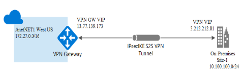
The following steps create an IPsec Azure Virtual Network Gateway.
- Create a Resource Group.
- Create the Virtual Network.
- Create a Virtual Network Gateway.
- Configure Local Network Gateway.
- Create Site-to-site Connections.
For more information on creating an IPsec Azure Virtual Network Gateway, refer to: https://docs.microsoft.com/en-us/azure/vpn-gateway/vpn-gateway-howto-site-to-site-resource-manager-portal
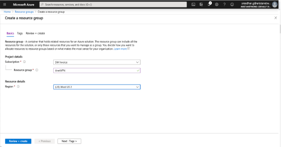
Creating a Resource Group
- Create a new resource group. Create all other resources, such as Virtual Network Gateway, Virtual Networks, and other resources under this group. For example, create an AnetVPN as a resource group.
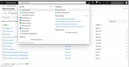
Creating a Virtual Network
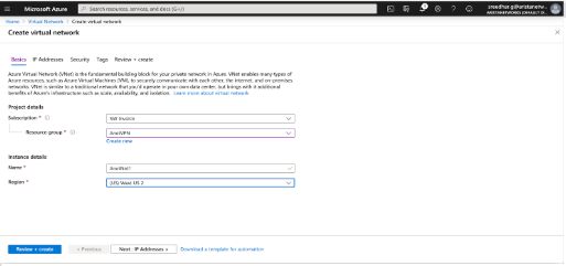
- Create a virtual network on the Azure Cloud and reachable through the Azure Virtual Network Gateway. For example, create a virtual network, AnetNet1 , with an IP address space of 172.27.0.0/16 and an AnetSubnet1(172.27.1.0/24) as the subnet for Virtual Network Gateway.
- Click Create .
- Enter the project details in the mandatory fields within the Project Details section.
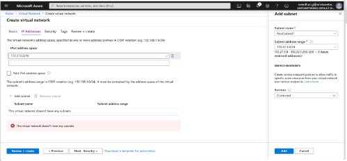
- Enter the IP address section with the IP address and Subnets.
- Click Review+create to validate the deployment.
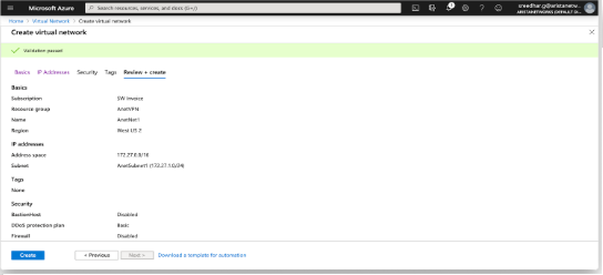
- Finally, this screen displays if the deployment passes the validation.
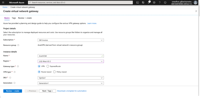
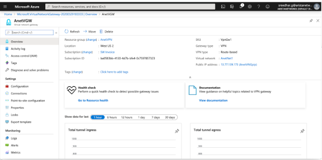
Creating a Virtual Network Gateway
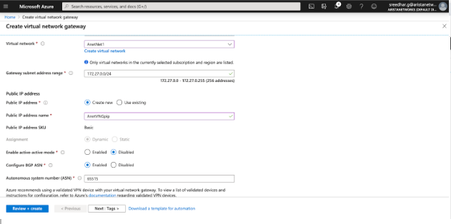
- Following the creation of the virtual network, proceed to establish a virtual network gateway (Arista's Virtual Gateway). Ensure that the Virtual Network Gateway is configured with a public IP address. While BGP is typically disabled by default on the Virtual Network Gateway, this specific example enables it to illustrate a BGP session functioning over the IPsec connection.
- Provide the public IP address name.
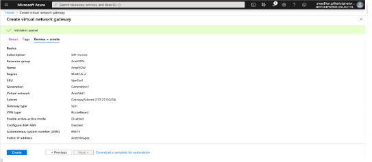
- Click Review+create to proceed with the deployment.
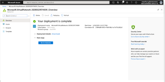
- Finally, you see this page on successful deployment.
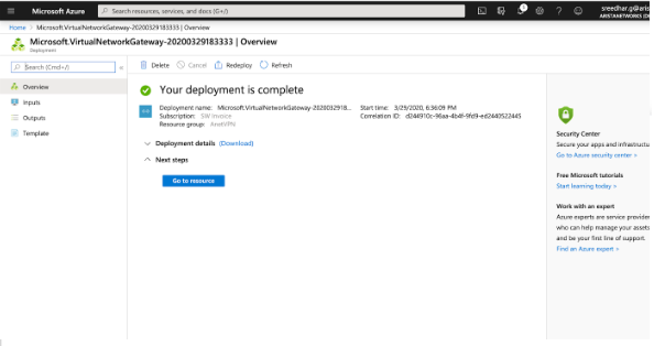
- This page provides information about the resources and other information related to the deployment.
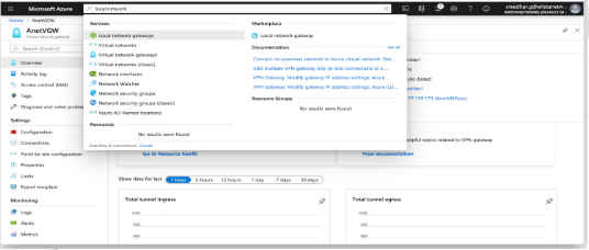
Configuring the Local Network Gateway
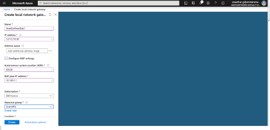
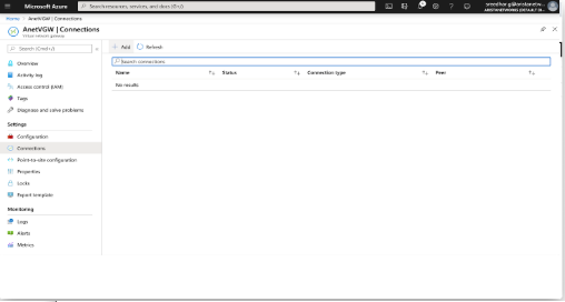
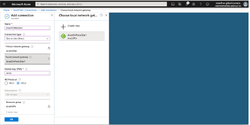
Creating Site-to-Site Connections
Configure a site-to-site connection and connect a Virtual Network Gateway to the Local Network Gateway. In addition to this, configure the IKE version and shared key used for IKE authentication. Configure the rest of the cryptographic parameters using PowerShell in Azure. Find the complete list of Azure cryptographic suites here .
Configuring AWE-7200R and CloudEOS Router IPsec
IKE - Ikev2/AES256/SHA256/DH-Group2
IPsec - ESP/AES256/SHA256
Configuring the IKE Policy
router(config-ipsec-ike)# ip security
router(config-ipsec)# ike policy ikeAzure
router(config-ipsec-ike)# encryption aes256
router(config-ipsec-ike)# integrity sha256
router(config-ipsec-ike)# version 2
router(config-ipsec-ike)# dh-group 2
router(config-ipsec-ike)# ex
router(config-ipsec)#
Configuring the SA Policy
router(config-ipsec)# sa policy saAzure
router(config-ipsec-sa)# esp encryption aes256
router(config-ipsec-sa)# esp integrity sha256
router(config-ipsec-sa)# ex
router(config-ipsec)#
Configuring the IPSec Profile
router(config-ipsec)# profile profAzure
router(config-ipsec-profile)# ike-policy ikeAzure
router(config-ipsec-profile)# sa-policy saAzure
router(config-ipsec-profile)# connection start
router(config-ipsec-profile)# shared-key arista
router(config-ipsec-profile)# ex
router(config-ipsec)#
Configuring the IPsec Tunnel (VTI) Interface
router(config)# interface Tunnel 1
router(config-if-Tu1)# ip address 10.100.1.1/24
router(config-if-Tu1)# tunnel mode ipsec
router(config-if-Tu1)# tunnel source 3.212.212.81
router(config-if-Tu1)# tunnel destination 13.77.139.173
router(config-if-Tu1)# tunnel ipsec profile profAzure
! IPSec adds an overhead of up to 82 bytes. Example: A GRE tunnel with an MTU=1476 should be changed to 1394 when using IPSec.
router(config-if-Tu1)# ex
router(config)#show
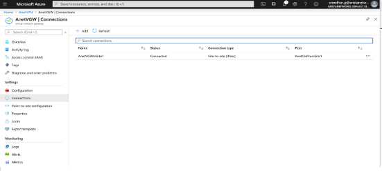
Verifying the IPsec Connection
router(config)# show ip security  connection
Tunnel    Source         Dest           Status       Uptime      Input     Output     Rekey Time
Tunnel1   3.212.212.81   13.77.139.173  Established  1 second    0 bytes   0 bytes    44 minutes
                                                                           0 pkts     0 pkts
Configuring an On Premises AWE-7200R and CloudEOS behind a NAT Device
router# ip security
   ike policy ikeAzure
      encryption aes256
      dh-group 2
      local-id 3.212.212.81
Configuring BGP over IPsec
CloudEOS(config)# router bgp 65530
CloudEOS(config-router-bgp)# neighbor 172.27.0.254 remote-as 65515
CloudEOS(config-router-bgp)# neighbor 172.27.0.254 update-source Tunnel1
CloudEOS(config-router-bgp)# neighbor 172.27.0.254 ebgp-multihop 4
CloudEOS(config-router-bgp)# address-family ipv4
CloudEOS(config-router-bgp-af)# neighbor 172.27.0.254 activate
CloudEOS(config-router-bgp-af)# network 10.100.100.0/24
CloudEOS(config-router-bgp-af)# ex
CloudEOS(config-router-bgp)# ex
CloudEOS(config)#
BGP Routes Advertised to Neighbor
router(config)# show ip bgp  neighbors 172.27.0.254 advertised-routes
BGP routing table information for VRF default
Router identifier 198.18.0.65, local AS number 65530
Route status codes: s - suppressed, * - valid, > - active, # - not installed, E - ECMP head, e - ECMP
                    S - Stale, c - Contributing to ECMP, b - backup, L - labeled-unicast, q - Queued for advertisement
                    % - Pending BGP convergence
Origin codes: i - IGP, e - EGP, ? - incomplete
RPKI Origin Validation codes: V - valid, I - invalid, U - unknown
AS Path Attributes: Or-ID - Originator ID, C-LST - Cluster List, LL Nexthop - Link Local Nexthop

      Network           Next Hop     Metric  LocPref Weight  Path
 * >  10.100.100.0/24   10.100.1.1   -       -       -       65530 i
BGP Routes Received from the Neighbor
router(config)# show ip bgp  neighbors 172.27.0.254  received-routes
BGP routing table information for VRF default
Router identifier 198.18.0.65, local AS number 65530
Route status codes: s - suppressed, * - valid, > - active, # - not installed, E - ECMP head, e - ECMP
                    S - Stale, c - Contributing to ECMP, b - backup, L - labeled-unicast
                    % - Pending BGP convergence
Origin codes: i - IGP, e - EGP, ? - incomplete
RPKI Origin Validation codes: V - valid, I - invalid, U - unknown
AS Path Attributes: Or-ID - Originator ID, C-LST - Cluster List, LL Nexthop - Link Local Nexthop

      Network          Next Hop       Metric  LocPref Weight  Path
 * >  172.27.0.0/16    172.27.0.254   -       -       -       65515 i
router(config)#
Verifying the BGP Connection
router(config)# show ip bgp summmary
BGP summary information for VRF default
Router identifier 198.18.0.65, local AS number 65530
Neighbor Status Codes: m - Under maintenance
  Neighbor      V  AS      MsgRcvd   MsgSent InQ OutQ  Up/Down    State   PfxRcd PfxAcc
  172.27.0.254  4  65515   194       214     0   0      00:00:06  Estab   1      1
router(config)#