Status Indicators
Supervisor Module
The supervisor displays the switch component status and contains Ethernet management and console ports. The Front Panels display the supervisor's location on the switches.
The supervisor provides one serial console port, two Ethernet management ports (one RJ-45, one optical), and one USB port. Four LEDs on the top edge report system status, fan status, power status, and switch module status. The following figure shows the LED status of the supervisor module.
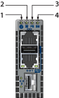
| 1 | System Status LED | 3 | Power Supply Status LED |
| 2 | Fan Status LED | 4 | Switch Card Status LED |
Supervisor Status LEDs
The following table interprets the states of the LED indicators on the supervisor module. When indicating error conditions, refer to LEDs on the specified components to determine the condition’s source.
| LED Name | LED State | Module State |
|---|---|---|
| Power Supply | Green | All powered modules are operating normally. |
| Red | At least one module has failed. | |
| System | Green | All linecards are operating normally. |
| Red | At least one linecard has failed. | |
| Switch Card | Green | Module is operating normally. |
| Red | Module has failed. | |
| Fan | Amber | At least one fan is missing or has failed. |
| Green | All modules are operating normally. | |
| Red | Additional functional fans need to be installed on the switch. |
Line Card Module Indicators
Each line card module provides one status LED plus LEDs for each port on the card. The figures in Linecards indicate the location of the LEDs on each line card. The following figure displays the status LED and Port LEDs on the DCS-7368-16C line card. Arrows indicate the port status being displayed by the corresponding port status LED.
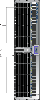
| 1 | Linecard Port LEDs | 2 | Linecard Status LED | 3 | Linecard Ejector Latch |
The Line Card Status LED is in the center of the DCS-7368-16C. The following table interprets the states of the Status LED.
| LED State | Status |
|---|---|
| Off | Line card not inserted. |
| Green | Line card operating normally. |
| Amber | Line card administratively shut down. |
| Red | Line card has failed. |
The following tableinterprets the port LED states.
| LED State | Status |
|---|---|
| Off | The port link is down. |
| Green | Port link is up. |
| Yellow | Port is disabled in the software. |
Fan Module Status Indicators
The fan modules are inserted into the switch card module. Each switch contains one switch card and five fan modules. Rear Panels displays the rear panel of the switch. The following figure displays the fan module indicator. The fan handle color indicates the airflow direction. All fan modules must have the same color handle.
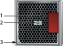
| 1 | Fan Release Handle | 2 | Fan Installation Indicator | 3 | Fan Status LED |
The fan installation Indicator is green when the fan module is properly installed or red when the module is not fully installed. The following table interprets the states of the Fan Status LED.
| LED State | Status |
|---|---|
| Off | The module is inserted but not receiving power – it may not be properly seated. |
| Green | The module is operating normally. |
| Red | The module has failed. |
Power Supply Status Indicators
Power Supply LEDs are on power supply modules. The rear panel contains power supply modules for all switches. The Rear Panels display the position of these LEDs on each switch.
The following figure displays a power supply module.
The power supply handle indicates the power supply fan direction. Verify that the airflow direction of all modules has the same color handles.
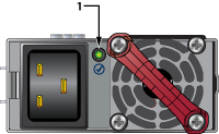
| 1 | Power Supply Status LED |
The following table interprets the state of the Power Supply Status LED.
| LED | Status |
|---|---|
| Green | Power Supply module operating normally. |
| Off | No AC power to the module. |
| Red | Module has faulted. |
| Blinking Green | PSU has AC power but hasn't been enabled by the system - indicates that either the power supply or the Switch Module isn't fully inserted. |