Layer 1 Profiles
Layer 1 (L1) profiles consists of a set of configurations that allow changing of the numbering schemes and default l1 configurations of all front panel interfaces on the switch. On Arista network switches, the front panel transceiver cages expose ports numbered sequentially. The front panel has the identifiers printed on them to allow for easier identification.
Depending on the networking technology, ports may have one or more signaling lanes that can group together to create one or more data channels with different data rates. As an example, a copper QSFP28 transceiver has 4 underlying signaling lanes which can be grouped together to pass a single 100Gbps channel connecting to a single peer or splitting into 4 independent channels running at 25 Gbps, each potentially connecting to 4 different peers. This creates a split configuration called a breakout.
By default, EOS exposes a number of interfaces on a port depending on the number of configurable signaling lanes. An OSPF transceiver cage on a fixed system numbered port 1 exposes 8 interfaces, Ethernet1/1 to Ethernet1/8. However, an RJ45 port only exposes a single interface with a number that matches the port number. Depending on the specifications, these interfaces have a default L1 configuration.
The interface numbering system and default port speed assignment may not be ideal for all network configurations. In this case, use a default L1 profile to renumber EOS interface names and defaults.
Platform Compatibility
- DCS-7050SX3-48C8
- DCS-7050SX3-48C8C
- DCS-7050SX3-48YC8
- DCS-7050SX3-48YC8C
- DCS-7050TX3-48C8
- DCS-7060DX4-32S
- DCS-7060DX4-32SB-RV3
- DCS-7260CX3-64
- DCS-7260CX3-64E
- DCS-7280CR3A-24D12
- DCS-7280CR3AK-24D12
- DCS-7280CR3AM-24D12
- DCS-7280DR3A-36-F
- DCS-7280DR3A-54-F
- DCS-7388-8D
- DCS-7388-8DR
- DCS-7800R3-36
- DCS-7800R3A-36P
L1 Module Profiles
A module profile contains a preset configuration that describes the behavior of every port on a given module. Configure these profiles on supported SKUs to achieve the desired interface numbering and default configuration schemes.
| Profile | Compatible SKUs |
|---|---|
| Uniform-4x100G-2-R |
|
| Uniform-4x10G-1 |
|
| Mixed-Max-8-Way-Breakout |
|
| Uniform-1x400G-8 |
|
| Max-Qsa |
|
| Uniform-2-Way-CF | DCS-7060X6-64PE |
Uniform-4x100G-2-R
This profile modifies all Octal ports (OSFP/QSF-DD) on the affected module and changes the interface names and default speeds:
| Old Interface Name | New Interface Name | Default Speed |
|---|---|---|
| EthernetX/Y/1 | EthernetX/Y/1 | 100G-2 |
| EthernetX/Y/2 | N/A | N/A |
| EthernetX/Y/3 | EthernetX/Y/2 | 100G-2 |
| EthernetX/Y/4 | N/A | N/A |
| EthernetX/Y/5 | EthernetX/Y/3 | 100G-2 |
| EthernetX/Y/6 | N/A | N/A |
| EthernetX/Y/7 | EthernetX/Y/4 | 100G-2 |
| EthernetX/Y/8 | N/A | N/A |
Uniform-4x10G-1
This profile modifies all Octal ports (OSFP/QSF-DD) on the affected module and changes the interface names and default speeds:
| Old Interface Name | New Interface Name | Default Speed |
|---|---|---|
| EthernetX/Y/1 | EthernetX/Y/1 | 10G-1 |
| EthernetX/Y/2 | EthernetX/Y/2 | 10G-1 |
| EthernetX/Y/3 | EthernetX/Y/3 | 10G-1 |
| EthernetX/Y/4 | EthernetX/Y/4 | 10G-1 |
| EthernetX/Y/5 | N/A | N/A |
| EthernetX/Y/6 | N/A | N/A |
| EthernetX/Y/7 | N/A | N/A |
| EthernetX/Y/8 | N/A | N/A |
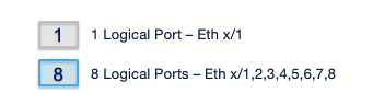
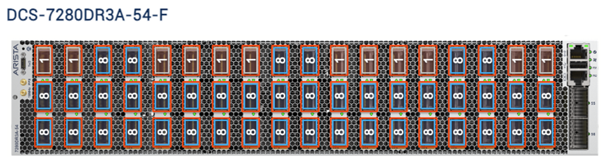
Mixed-Max-8-Way-Breakout-V1
This profile enables certain SKUs to configure the maximum number of breakouts on some Octal Ports, OSFP and QSFP-DD, while disabling or limiting breakout support on others. The profile provides this option only for certain SKUs, and you should consult the SKU or SKU family white papers for a full list of caveats and target network applications.
To understand the port diagrams, use the following legend:
![]()
Uniform-1x400G-8
The profile modifies all Octal Ports, OSFP and QSFP-DD, on the affected module so that for each port has only one interface with a default speed of 400G-8.
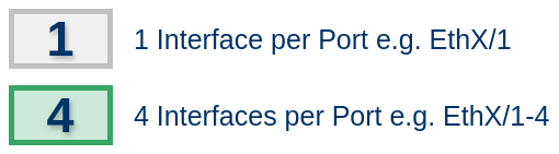
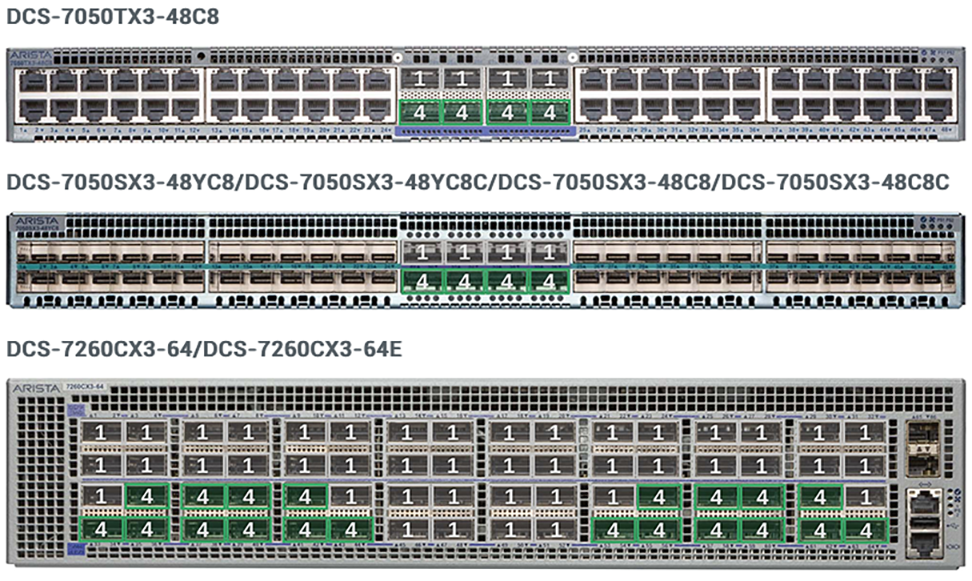
MAX-QSA
Designed to enable certain SKUs to deploy QSA modules in any and all of the QSFP ports on the system. This disables breakout support on some of the QSFP ports, and you should consult the SKU or SKU family white papers for a full list of caveats and target network applications.
To understand the port diagrams, use the following legend:
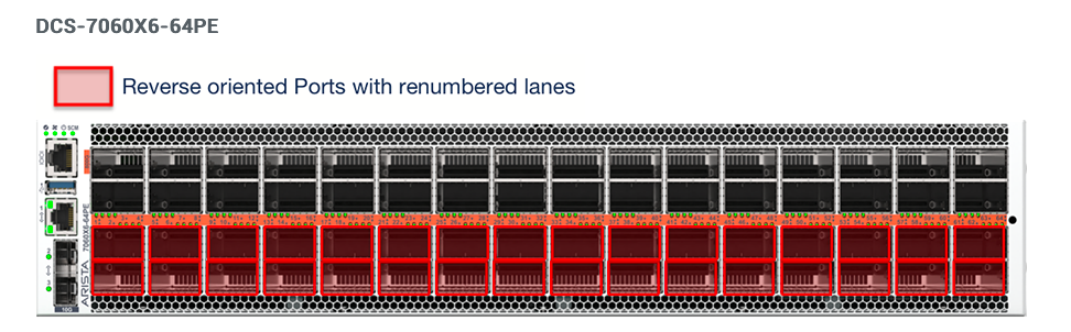
Uniform-2-Way-CF
Certain switches, such as the DCS-7060X6-64P, contain ports oriented in different directions where the ports in the bottom two rows and the top two rows go in different directions. In this case, the transceivers must be inserted in a different orientation depending on the location of the row. This becomes more complex when dual optical fiber transceivers must be inserted.
Uniform-2-Way-R
This profile modifies all ports on the switch to contain two configurable interfaces per port and renumbers the lanes. For example, on an octal form factor port, such as an OSFP or QSFP-DD, the ports renumber as follows:
| Old Interface Name | New Interface Name |
|---|---|
| EthernetX/Y/1 | EthernetX/Y/1 |
| EthernetX/Y/2 | |
| EthernetX/Y/3 | |
| EthernetX/Y/4 | |
| EthernetX/Y/5 | EthernetX/Y/2 |
| EthernetX/Y/6 | |
| EthernetX/Y/7 | |
| EthernetX/Y/8 |