
Rack Mounting the Switch
Rack Mounting the Switch (1RU)
- Two-Post Rack Mount (1RU)
Note: Use the rack-mount parts included with your switch for mounting. For heavier switches, only a four-post mount is supported.
- Four-Post Rack Mount (1RU)
The following sections detail rack mounting in two-post and four-post racks for 1 RU switches.
The rack mounting procedure is identical for all switches covered by this guide. Illustrations in this chapter depict the mounting of a representative switch.
La procédure de montage en rack est identique pour tous les commutateurs couverts par ce guide. Les illustrations de ce chapitre illustrent le montage d'un commutateur représentatif.
- Two-Post Rack Mount (1RU) provides instructions for mounting the switch in a two-post rack.
- Four-Post Rack Mount (1RU) provides instructions for mounting the switch in a four-post rack.
After completing the instructions for your rack type, proceed to Cabling the Switch.
Two-Post Rack Mount (1RU)
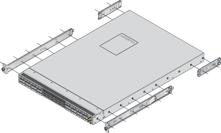
To mount the switch onto a two-post rack, assemble the mounting brackets to the chassis, then attach the brackets to the rack posts. Two-post accessory kits include the following two-post mounting parts.
2 - Three-hole Mounting Brackets
Each chassis side has attachment pins that align with bracket holes. Pin orientation is symmetric and equidistant, supporting bracket placements where the flange is flush with the front switch panel, flush with the rear panel, or not flush with either panel. Each bracket hole includes a key-opening for placing the bracket flush with the chassis and then locking it into place.
Attachment pins must engage all three upper bracket holes.
Les goupilles de fixation doivent être bloquées tous les trois trous de la bride supérieure.
Attaching Mounting Brackets to the Chassis (Two-Post)
The following figure displays the front bracket alignment for attaching the switch to a two-post rack.
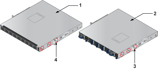
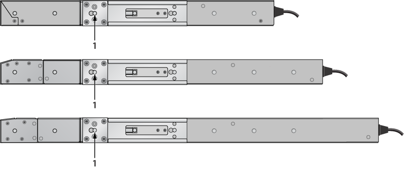
The following figure displays examples of improper bracket mounts for a two-post rack mount.
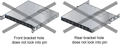
The following procedure attaches the two-post rack mount brackets to the chassis.
- Align the mounting brackets with the attachment pins to obtain the desired mounting position.
- Place the bracket flush on the chassis with attachment pins protruding through key-openings.
- Slide the bracket toward the front flange until the bracket clip locks with an audible click.
The following figures show the correct bracket attachment for a center mount.
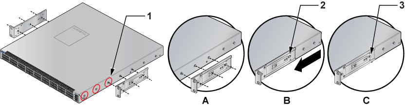
To remove the mounting bracket from the chassis, lift the front edge of the mounting bracket clip with a flathead screwdriver and slide the bracket away from the front flange (opposite from the installation direction).
Inserting the Switch into the Rack (Two-Post)
This procedure attaches the switch to the rack.
- Lift the chassis into the rack. Position the flanges against the rack posts.
- Select mounting screws that fit your equipment rack.
- Attach the bracket flanges to the rack posts.
Figure 4. Inserting the Switch into the Rack 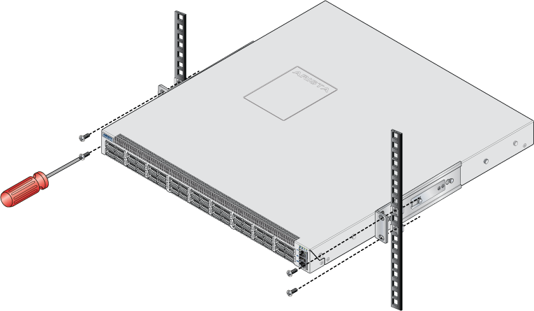
After completing the two-post rack mount, proceed to Cabling the Switch.
Four-Post Rack Mount (1RU)
The switch is mounted onto a four-post rack by assembling two rails onto the rear posts, sliding the switch onto the rails, and then securing the switch to the front posts.
- 2 six-hole mounting brackets
- 2 rail-rods
- 2 rail-slides
The rail-rods and rail-slides assemble into two identical slide-rails.
Each chassis side has attachment pins that align with bracket holes. Pin orientation is symmetric and equidistant, supporting bracket placements where the flange is flush with the front switch panel, flush with the rear panel, or not flush with either panel. Each bracket hole includes a key-opening for placing the bracket flush with the chassis and then locking it into place.
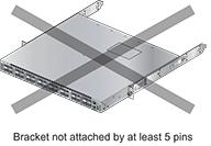
Attachment pins must engage at least five of the six bracket holes.
Goupilles de fixation doivent être lock au moins cinq des trous du six support.
The following figure displays proper bracket mount configuration examples for four-post mounting.
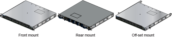
The following figure displays an example of an improper bracket mount configuration.
Attaching Mounting Brackets to the Chassis (Four-Post)
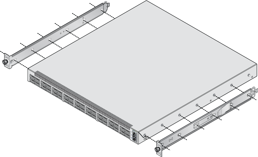
This procedure attaches mounting brackets to the switch chassis as depicted by the preceding figure(s).
- Align the mounting brackets with the attachment pins to obtain the desired mounting position.
- Place the bracket flush on the chassis with attachment pins protruding through key-openings.
- Slide the bracket toward the front flange until the bracket clip locks with an audible click.
- Attach the deep chassis adapters as needed.
To remove the mounting bracket from the chassis, lift the front edge of the mounting bracket clip with a flathead screwdriver and slide the bracket away from the front flange (opposite from the installation direction).
The rest of the rack mounting steps are the same for both KIT-7001 and KIT-7101.
Assembling the Rails onto the Equipment Rack
Rail-rods and rail-slides assemble into two identical rails. Each rail connects a front post to a rear post. When the rails are installed, the switch slides on the rails into the rack. Each bracket includes a screw that attaches the switch to the rail.
Each end of an assembled rail contains two rack plugs (Figure 9 - Attaching the Four-Post Mounting Brackets to the Switch Chassis). The rails are installed into a rack by inserting the plugs into the rack slots. When installing rails into posts with threaded or rounded holes, remove all plugs located on both sides of the assembled rails, then install the rails with bolts that fit the rack.
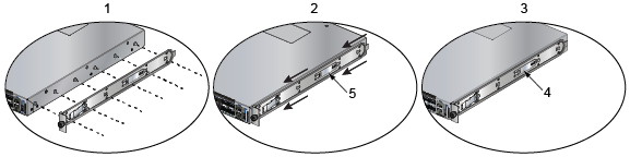
| 1 | Step 1 | 2 | Step 2 | 3 | Step 3 |
| 4 | Bracket clip (attached) | 5 | Bracket clip (aligned) |
This procedure attaches the rails to a four-post rack:
- Slide a rail-rod into a rail-slide (Figure 10 - Assembling the Rails) until the rail clip makes an audible click.
The rail clip prevents the extension of the rail beyond the maximum supported distance between the front and rear rack posts.
Figure 10. Assembling the Rails 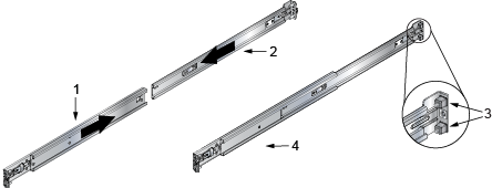
1 Rail-slide 3 Rack plugs 2 Rail-rod 4 Rail (assembled) - Repeat Steps 1 through 3 for the left posts. Ensure the rails are on the same horizontal level.
Figure 11. Attaching the Rails 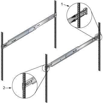
1 Inset A 2 Inset B
Attaching the Switch to the Rack
After the rails are installed, the switch slides on the rails into the rack. Each bracket includes a thumb screw that attaches the switch to the rail.
- Lift the switch into the rack and insert the mounting brackets into the slide rails.
Figure 12. Inserting the Switch onto the Rails 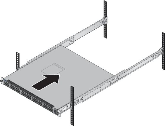
- Slide the switch on the rails, toward the rear posts, until the mounting bracket flanges are flush with the rail flanges attached to the rack posts.
- Attach the bracket flanges to the rack post using the quick-release thumb screws supplied with the brackets Figure 13 - Attaching the Switch to the Rack Posts. Hand-tighten the thumb screws or use a Phillips #2 screwdriver.
Note: Do not exceed a maximum torque of 20in-lb or use powered impact drivers to secure the thumb screws.
Figure 13. Attaching the Switch to the Rack Posts 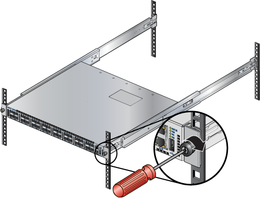
After completing the four-post rack mount, proceed to Cabling the Switch.