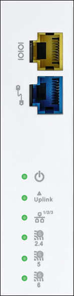
The right panel of the access point has 6 LEDs that indicate the functioning state of the device, one console port, and one passthrough port.
Figure 1. W-318/W-318 RW Right Panel
The following table describes the ports available on the right panel of the AP:
Table 1. Right Panel Ports and Description
Port
Description
Connector Type
Speed/Protocol
Console
Port to establish a ‘config shell’ terminal session through a serial connection.
RJ-45
RS 232 Serial (115200 bits per second)
Data bits:8; Stop bits: 1
Parity: None
Flow Control: None
Passthrough
A wired port that facilitates extension of the wired network after mounting the APon the wall or stand. You can plug another device into the passthrough port of the AP. The traffic on the passthrough port does not interfere with the AP traffic. You cannot apply any policies on the passthrough port traffic.
Device connected through the Uplink port (Ethernet port) at 10/100/1000 Mbps
NA
The following table indicates the device states based on the LEDs.
Table 2. AP LED Status Description
LED
Status
Description
Power
Solid Green
Power ON
OFF
Power OFF
Uplink
Solid Green
Device connected through the Uplink port (Ethernet port) at 10/100/1000 Mbps
Blinking Green
Activity on the Uplink port
LAN1/2/3
Solid Green
Device connected to LAN port 1/2/3 on the bottom of the device at 10/100/1000 Mbps
2.4 GHz
Solid Green
No activity on 2.4 GHz radio
Blinking Green
Wireless activity on 2.4 GHz radio
5 GHz
Solid Green
No activity on 5 GHz radio
Blinking Green
Wireless activity on 5 GHz radio
6 GHz
Solid Green
No activity on 6 GHz radio
Blinking Green
Wireless activity on 6 GHz radio
Rear Panel of the Access Point
The rear panel of the access point (AP) has an Ethernet port labeled Uplink that enables you to connect the AP to a wired LAN through a switch or a hub. The Uplink port powers the AP using the 802.3bt standard.
Figure 2. W-318/W-318 RW Rear Panel
Table 3. W-318/W-318 RW Rear Panel
Port
Description
Connector Type
Speed/Protocol
Passthrough
A wired port that facilitates extension of the wired network after mounting the AP on the wall or stand. Another device can be plugged-in to the pass-through port of the AP. The traffic on the pass-through port does not interfere with the AP traffic. No policies can be applied on the pass-through port traffic.
RJ45
-
Uplink
Enables you to connect the AP to a wired LAN through a switch or a hub. The AP can then communicate with the server. This port also provides the power for the device using the 802.3bt standard
RJ45
10/100/1000 Mbps Power over Ethernet
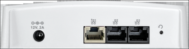
Bottom Panel of the Access Point
The bottom panel of the access point and its corresponding ports are described below.
Figure 3. W-318/W-318 RW Bottom Panel
Table 4. W-318/W-318 RW Bottom Panel
Port
Description
Connector Type
Speed/Protocol
DC In
Enables you to connect to and power on the access point using 12 V DC power with 2 Ampere.
5.5mm overall diameter/2.1mm center pin/hole
NA
Ethernet (LAN1/PSE)
Gigabit Ethernet port can wire an SSID extension. This Power Sourcing Equipment (PSE) port also provides power to the connected device using the 802.3af standard.
RJ45
10/100/1000 Mbps Gigabit Ethernet
Ethernet (LAN2)
Gigabit Ethernet port can be used to wire an extension for an SSID.
RJ45
10/100/1000 Mbps Gigabit Ethernet
Ethernet (LAN3)
Gigabit Ethernet port can be used as a wired SSID extension.
RJ45
10/100/1000 Mbps Gigabit Ethernet
Reset
Resets the access point to factory defaults to reset the access point, press and hold the Reset Pin Hole until all LEDs go off, which indicates that the access point has rebooted. Pressing the Reset Pin Hole while the access point boots up does not have any effect. Perform this operation only when the access point is running.
Pinhole push button
Hold down and power cycle the access point to reset.