Preparation
The following topics are covered in this section:
Site Selection
The following criteria should be considered when selecting a site to install the switch:
- Temperature and Ventilation: For proper ventilation, install the switch where there is ample airflow to the front and back of the switch. The ambient temperature should not go below 0° or exceed 40°C.
Important: To prevent the switch from overheating, do not operate it in an area where the ambient temperature exceeds 40°C (104°F).
Pour empêcher l'interrupteur de surchauffe, ne pas utiliser il dans une zone où la température ambiante est supérieure à 40°C (104°F).
- Airflow Orientation: The fans and PSUs determine the airflow direction through the switch. The color of the visible handles or labels indicate the airflow direction.
Note: The figures shown use representative Arista switches to illustrate airflow directions. For some switches, label color indicates the airflow direction.
- Blue Handle: Air Inlet module. The following figure shows the airflow through the switch with air inlet modules:
Figure 1. Air Inlet Module 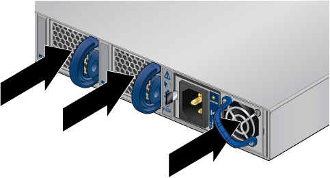
- Red Handle: Air Exit module. The following figure shows the airflow through the switch with air exit modules:
Figure 2. Air Exit Module 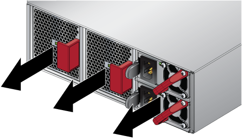
- Blue Handle: Air Inlet module. The following figure shows the airflow through the switch with air inlet modules:
- Rack Space: Install the switch in a 19" rack or cabinet. The switch height is 2 RU. The accessory kit provides mounting brackets for four-post racks. Contact your sales representative to obtain two-post mounting brackets.
When mounting the switch in a partially filled rack, load the rack from bottom to top, with the heaviest equipment at the bottom. Load the switch at the bottom if it is the only item in the rack.
- Power Requirements: Power requirements vary by switch and power supply model. Refer to Table 3 for information regarding your specific system.
Two circuits provide redundancy protection. Grounding the Switch describes power cable requirements.
Important: The power input plug-socket combination must be accessible at all times; it provides the primary method of disconnecting power from the system.La combinaison de la puissance-prise d'entrée doit être accessible en tout temps ; Il fournit le principal moyen de coupure d'alimentation du système.
- Other Requirements: Select a site where liquids or objects cannot fall onto the equipment and foreign objects are not drawn into the ventilation holes. Verify these guidelines are met:
- Clearance areas to the front and rear panels allow for unrestricted cabling.
- All front and rear panel indicators can be easily read.
- Power cords can reach from the power outlet to the connector on the rear panel.
Important: All power connections must be removed to de-energize the unit.
Toutes les connexions d'alimentation doivent être enlevées pour hors tension l'appareil.
Important: This unit is intended for installation in restricted access areas.Cet appareil est prévu pour une installation dans les zones d'accès restreintes.
Reconfiguring Air Flow
Some switches allow configuration with either front-to-rear or rear-to-front airflow. To reconfigure a system, de-energize the unit and replace all fans and power supplies with the desired orientation. Mixing front-to-rear and rear-to-front components is not supported and will impact the cooling capacity of the switch.
DCS-7260CX3 and DCS-7170-64 systems contain additional louvers behind the fan tray. These louvers follow the same color coding as the fans and must be removed, rotated and replaced when changing airflow orientation.
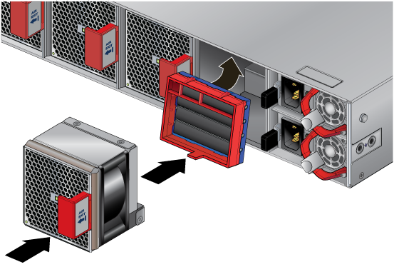
- Lift the tab up.
- Rotate and remove the louver.
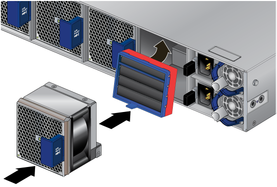
- Rotate the louver so the desired color is on the outside.
- Slide and seat the louver until it clicks into place.
Tools and Parts Required for Installation
The following tools and equipment are required to install the switch:
Two-Post Rack
- Screws or rack mounting nuts and bolts.
- Screwdriver
Four-Post Rack (Toolless)
No additional equipment required.
Accessory kit does not include screws for attaching the switch to the equipment rack. When installing the switch into an equipment rack with unthreaded post holes, nuts are also required to secure the switch to the rack posts.
Electrostatic Discharge (ESD) Precautions
- Assemble or disassemble equipment only in a static-free work area.
- Use a conductive work surface (such as an anti-static mat) to dissipate static charge.
- Wear a conductive wrist strap to dissipate static charge accumulation.
- Minimize handling of assemblies and components.
- Keep replacement parts in their original static-free packaging.
- Remove all plastic, foam, vinyl, paper, and other static-generating materials from the work area.
- Use tools that do not create ESD.