Rear Panel
All switches covered by this guide use one of the rear panels shown below. Depending on the installed power supply module, the appearance could be different from those shown.
Note: All devices are designed to fit into a 19” rack. The appearance may be different than those shown based on the PSU and the fan modules used.
Note: Handle or label color indicates airflow direction.
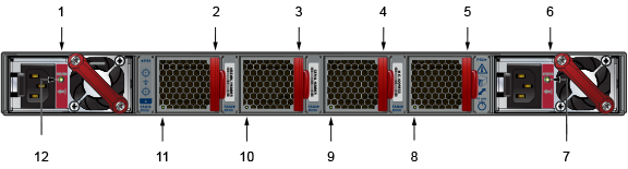
| 1 | Power supply module 1 | 5 | Fan module 4 | 9 | Fan module 3 status LED |
| 2 | Fan module 1 | 6 | Power supply module 2 | 10 | Fan module 2 status LED |
| 3 | Fan module 2 | 7 | PSU module 2 status LED | 11 | Fan module 1 status LED |
| 4 | Fan module 3 | 8 | Fan module 4 status LED | 12 | PSU module 1 status LED |
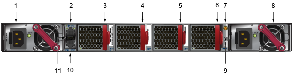
| 1 | Power supply module 1 | 5 | Fan module 3 | 9 | Earth grounding pad |
| 2 | Ethernet management port | 6 | Fan module 4 | 10 | Console serial port |
| 3 | Fan module 1 | 7 | Clock Input | 11 | USB port |
| 4 | Fan module 2 | 8 | PSU 2 |
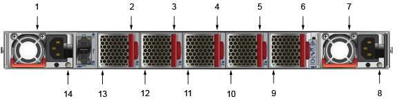
| 1 | Power supply module 1 | 6 | Fan module 5 | 11 | Fan module 3 status LED |
| 2 | Fan module 1 | 7 | PSU 2 | 12 | Fan module 2 status LED |
| 3 | Fan module 2 | 8 | PSU 2 status LED | 13 | Fan module 1 status LED |
| 4 | Fan module 3 | 9 | Fan module 5 status LED | 14 | PSU 2 status LED |
| 5 | Fan module 4 | 10 | Fan module 5 status LED |
The following figure shows the DCS-7060DX4-32C-RV3-F switch assembly designed to be mounted in an ORv3 rack.
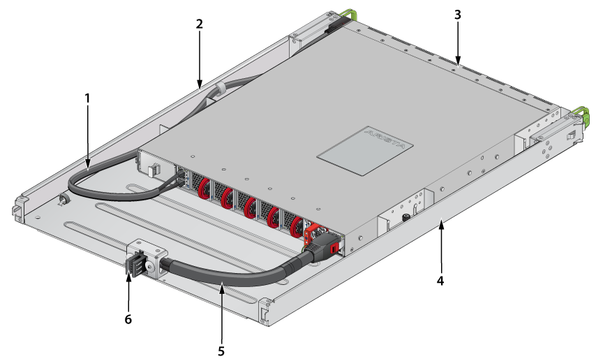
| 1 | Cable to management ports | 3 | Switch | 5 | DC power cable |
| 2 | Tray side | 4 | Tray side | 6 | DC power connector |