Cabling the Switch
4.1 Grounding the Switch
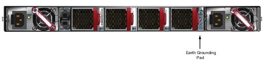
After mounting the switch into the rack, connect the switch to the data center ground. Figure 4-1 displays the location of the grounding pads located on the bottom corners of the rear panel for the models that have no management ports on the rear panel. Figure 4-2 displays the location of the grounding pads on the rear panel for models that have management ports on the rear panel. There are threaded holes under the sticker on the right (next to PS2) that warns about “1 min”.
Important! Grounding wires and grounding lugs (M4 x 0.7) are not supplied. Wire size should meet local and national installation requirements. Commercially available 6 AWG wire is recommended for installations in the U.S
À la terre et de mise à la terre fils cosses (M4 x 0.7) ne sont pas fournis. Calibre des fils doit satisfaire des exigences de l’installation locale et nationale. Disponible dans le commerce 6 fils AWG est recommandé pour les installations aux États-Unis.
À la terre et de mise à la terre fils cosses (M4 x 0.7) ne sont pas fournis. Calibre des fils doit satisfaire des exigences de l’installation locale et nationale. Disponible dans le commerce 6 fils AWG est recommandé pour les installations aux États-Unis.
Figure 4-1: Earth Grounding Pad Sockets for Models without Management Ports on the Rear Panel
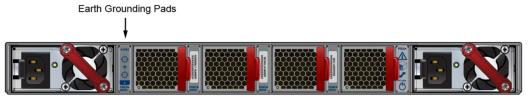
Figure 4-2: Earth Grounding Pad Sockets for Models with Management Ports on the Rear Panel
4.2 Connecting Power Cables
Important! Installation of this equipment must comply with local and national electrical codes. If necessary, consult with the appropriate regulatory agencies and inspection authorities to ensure compliance.
Installation de cet équipement doit être conformes aux codes électriques locaux et nationaux. Si nécessaire, consulter les organismes de réglementation appropriés et des autorités de contrôle pour assurer la conformité.
Installation de cet équipement doit être conformes aux codes électriques locaux et nationaux. Si nécessaire, consulter les organismes de réglementation appropriés et des autorités de contrôle pour assurer la conformité.
The switch operates with two installed power supplies. At least one power supply must connect to a power source. Two circuits provide redundancy protection. Appendix D displays the location of the power supplies on the rear panel of the switch.
Important! Read all installation instructions before connecting the system to the power source.
Lire toutes les instructions d’installation avant de brancher le système à la source d’alimentation.
Lire toutes les instructions d’installation avant de brancher le système à la source d’alimentation.
• Non-Redundant Configuration: Connect power to either of the two power supplies.
• Redundant Power Supply Configuration: Connect power to both power supplies.
• Power down the Switch: Remove all power cords and wires from the power supplies.
Important! This equipment must be grounded. Never defeat the ground conductor.
Cet équipement doit être mis à la terre. Ne jamais modifier le conducteur de terre.
Cet équipement doit être mis à la terre. Ne jamais modifier le conducteur de terre.
Important! This unit requires overcurrent protection.
Cet appareil requiert une protection contre les surintensités.
Cet appareil requiert une protection contre les surintensités.
4.2.1 AC Power Supplies
The following AC power supplies are supported.
• PWR-500AC
• PWR-747AC
Figure 4-3 displays an AC power supply, including the power socket on the left side of the module. The AC power supply connects to a circuit that provides the required power, as specified by Table 1-4.
Figure 4-3: AC Power Supply
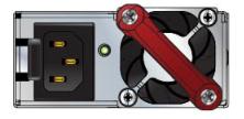
The power supplies require power cables that comply with IEC-320 and have a C13 plug. The accessory kit provides two IEC-320 C13 to C14 power cables.
4.2.2 DC Power Supplies
The following two DC power supplies are supported.
• PWR-1900-DC
• PWR-500-DC
Figure 4-4: Supported DC power supplies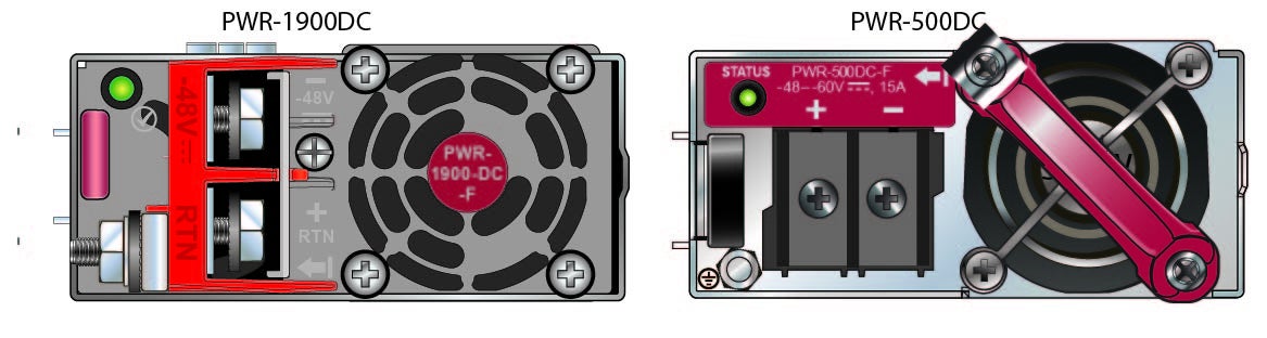
Important! A disconnect device must be provided as part of the installation .
Un dispositif de sectionnement doit être fourni dans le cadre de l'installation.
Un dispositif de sectionnement doit être fourni dans le cadre de l'installation.
Important! Ensure power is removed from DC circuits before performing any installation actions. Locate the disconnect device, circuit breakers or fuses on DC power lines servicing the circuits.
Turn off the power line circuits or remove the fuses.
Pouvoir assurer qu'il est retiré de circuits DC avant d'effectuer des actions d'installation . Localiser les disjoncteurs ou des fusibles sur les lignes de courant continu desservant les circuits.
Coupez les circuits de lignes d'alimentation ou retirer les fusibles.
Important! Wire size must comply with local and national requirements and electrical codes.
Use only copper wire.
Le calibre du fil doit être conforme aux exigences locales et nationales et les codes électriques.
Utiliser du fil de cuivre.
Use only copper wire.
Le calibre du fil doit être conforme aux exigences locales et nationales et les codes électriques.
Utiliser du fil de cuivre.
Important! Apply ground connection to the switch first during installation and remove last when removing power.
Appliquer connexion à la terre à l'interrupteur premier lors de l'installation et de supprimer la dernière alimentation lors du débranchement.
Appliquer connexion à la terre à l'interrupteur premier lors de l'installation et de supprimer la dernière alimentation lors du débranchement.
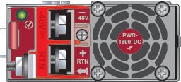
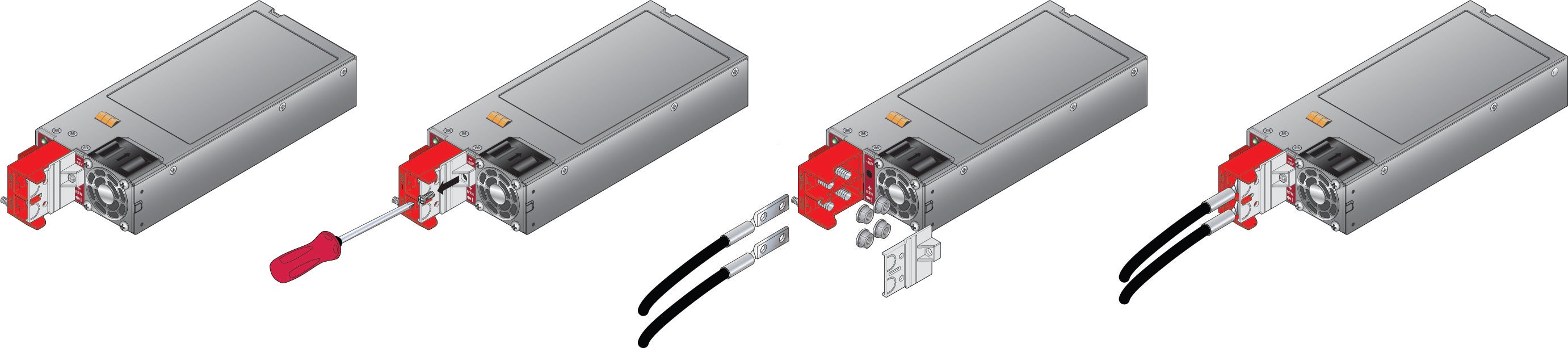
4.2.3 PWR-1900-DC Power Supply
Figure 4-5: PWR-1900-DC power supply
4.2.3.1 Wire and Lug Preparation
Before performing any installation actions, ensure power is removed from DC circuits by turning off the power line servicing the circuits. Prepare the stranded wiring before you begin a DC power installation.
Step 1 Attach an ESD grounding strap.
Step 2 Stranded copper wiring is required.
• Commercially available 4 to 6 AWG wire is recommended for installations in the U.S.
• Wire size should meet local and national installation requirements.
• Grounding wires and grounding lugs are not supplied.
• Strip the wires to the appropriate length for the lugs.
The wires connecting the DC power supply to the power source must meet the following requirements:
• DC Input Wire Size: 4 – 6 AWG (21.2 mm2 to 13.3 mm2).
• Primary Ground Wire Size: 4 – 6 AWG (21.2 mm2 to 13.3 mm2) per power supply.
• The conductors are copper.
Step 3 Use agency-approved compression (pressure) lugs for wiring terminations.
Step 4 Slip on heat-shrink tubing on the wire ends before assembling the lugs on to the wire.
• The lugs must be crimped with the proper tool.
• The tubing should extend over the lugs barrel and the wire's insulator.
• Shrink the tubing with a heat gun.
4.2.3.2 Connecting a DC Power Supply to Power Source
To connect a DC power supply to power source:
Step 1 Prepare the stranded wiring, see Section 4.2.3.1: Wire and Lug Preparation.
Step 2 Attach the appropriate lugs to the source DC wires.
Step 3 Connect the DC-input wires:
• Ground wire to the Protective Earth (PE  ) terminal.
) terminal.• Negative source DC cable to the negative (- / -48V) terminal.
• Positive (+) source DC cable to the positive (+ / Rtn) terminal.
• Tightening Torque: 2.7 N-m (24 in. lbs.)
4.2.4 PWR-500-DC Power Supply
The PWR-500W-DC power supply connects to a circuit that provides -48Vto -60V and 15A. Figure 4-6displays the DC power supply.
Figure 4-6: PWR-500-DC Power Supply

Ensure the wires connecting the DC power supply to the power source meet the following:
• DC Input Wire Size: AWG 14 (2.0 mm2) or larger as appropriate
• Safety Ground Wire Size: AWG 14 (2.0 mm2) or larger as appropriate
• Wire Terminal (Lug): ring or spade/fork, 14-16 AWG, #8 (4 mm) screw
• Over-current protection: 20 A.
Important! Ensure power is removed from DC circuits before performing any installation actions. Locate circuit breakers or fuses on DC power lines servicing the circuits. Turn off the power line circuits or remove the fuses.
Assurez-vous de pouvoir retirer des circuits en courant continu avant d’effectuer toute action d’installation.Localiser les disjoncteurs ou fusibles sur les lignes électriques DC entretien des circuits. Mettez hors tension le circuit ligne ou retirer les fusibles.
Assurez-vous de pouvoir retirer des circuits en courant continu avant d’effectuer toute action d’installation.Localiser les disjoncteurs ou fusibles sur les lignes électriques DC entretien des circuits. Mettez hors tension le circuit ligne ou retirer les fusibles.
To connect a DC power supply to power source:
Step 1 Remove the terminal cover to expose the connectors on the terminal block on the face.
Step 2 Attach the appropriate lugs to the source DC wires.
Use DC cables with either insulated crimp-on spade lugs or insulated crimp-on ring connectors.
Important! Wire size must comply with local and national requirements and electrical codes. Use only copper wire.
Calibre doit respecter les exigences locales et nationales et les codes de l’électricité. Utiliser seulement du fil de cuivre.
Calibre doit respecter les exigences locales et nationales et les codes de l’électricité. Utiliser seulement du fil de cuivre.
Step 3 Connect the DC-input wires to the terminal block in this order:
1. Ground cable to the ground connector on the face of the power supply.
2. Negative (–) source DC cable to the negative (–) connector on the terminal block.
3. Positive (+) source DC cable to the positive (+) connector on the terminal block.
4. Torque the screws to 1.0 N·m / 9 in·lb.
Important! Apply the ground connection first during installation and remove last when removing power.
Appliquer le motif connexion tout d’abord pendant l’installation et supprimer dernière lors du retrait de puissance.
Appliquer le motif connexion tout d’abord pendant l’installation et supprimer dernière lors du retrait de puissance.
5. Replace the terminal cover.
4.3 Connecting Serial and Management Cables
The accessory kit includes the following cables:
• RJ-45 to DB-9 serial adapter cable.
• RJ-45 Ethernet cable.
Table 4-1 lists the pin connections of the RJ-45 to DB-9 adapter cable.
|
RJ-45
|
DB-9
|
RJ-45
|
DB-9
|
|||||
|
RTS
|
1
|
8
|
CTS
|
GND
|
5
|
5
|
GND
|
|
|
DTR
|
2
|
6
|
DSR
|
RXD
|
6
|
3
|
TXD
|
|
|
TXD
|
3
|
2
|
RXD
|
DSR
|
7
|
4
|
DTR
|
|
|
GND
|
4
|
5
|
GND
|
CTS
|
8
|
7
|
RTS
|
|
Note RJ-45 to DB-9 connections: Models with management ports on the rear panel short RJ-45 pin 1 (RTS) to RJ-45 pin 8 (CTS). RJ-45 pins 2 (DTR) and RJ-45 pin 7 (DSR) are not electrically connected to anything.
For most models, the front panel contains the console, management, and USB ports. Figure 4-7 displays the ports on the front panel of the DCS-7050QX-32S switch. Figure 4-8 displays the ports on rear panel of the DCS-7280SR-48C6 switch. Appendix C and Appendix D display the front and rear panels of all switches covered by this guide.
Figure 4-7: Front Panel Ports
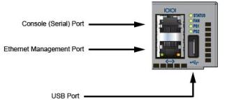
Figure 4-8: Rear Panel Ports
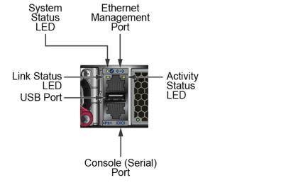
Connect the front or rear panel ports as follows:
• Console (Serial) Port: Connect to a PC with the RJ-45 to DB-9 serial adapter cable.
The switch uses the following default settings:
The switch uses the following default settings:
• 9600 baud
• No flow control
• 1 stop bit
• No parity bits
• 8 data bits
• Ethernet Management Port: Connect to 10/100/1000 management network with RJ-45 Ethernet cable.
• USB Port: The USB port may be used for software or configuration updates.
Caution Excessive bending can damage interface cables, especially optical cables.
Flexion excessive peut endommager les câbles d’interface, notamment des câbles optiques.
Flexion excessive peut endommager les câbles d’interface, notamment des câbles optiques.