Status Indicators
Supervisor Module
While the front panel of each switch can house two supervisors, switch operations require only one. Supervisors display switch component status and contain Ethernet management and console ports. Appendix C displays the supervisor location on each switch.
The supervisor style depends on the switch model. These sections describe both supervisor styles.
Supervisor Indicators: 7508/7504
The 7508/7504 supervisor provides a serial console port, an Ethernet management port, and a USB port. Supervisor activity is reported by LEDs in the upper left quadrant. The Status Summary Screen in the center reports status for other components. Figure A-1 depicts the 7508/7504 Supervisor Module.
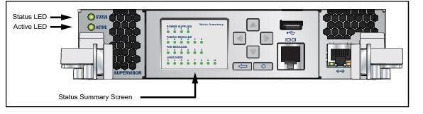
Figure A-1: Supervisor Module: 7508 / 7504
Supervisor Activity Status
The Status and Active LEDs report supervisor activity status. Table A-1 interprets the states of both LEDs.
|
LED Name
|
LED State
|
Supervisor State
|
|
Status LED
|
Off
|
Module failed or is improperly inserted.
|
|
Status LED
|
Green
|
Supervisor operating normally.
|
|
Status LED
|
Red
|
Module failed.
|
|
Active LED
|
Off
|
Supervisor is not active.
|
|
Active LED
|
Green
|
Supervisor is active and controlling the switch.
|
Component Activity Status
The Supervisor Status Summary Screen displays indicators for the power supplies, fabric module, fan modules and line cards. Table A-2 interprets the states of the indicators that the screen displays.
|
LED State
|
Status
|
|
Gray
|
Module not present or improperly inserted.
|
|
Green
|
Module operating normally.
|
|
Red
|
Module has failed.
|
Supervisor Indicators: 7508E / 7504E
The 7508E/7504E supervisor provides one serial console port, two Ethernet management ports, two USB ports, and one clock input port. Supervisor activity is reported by LEDs in the upper left corner. Four LEDs located left of the input ports report status of other switch components. Figure A-2 displays the 7508E/7504E Supervisor Module.
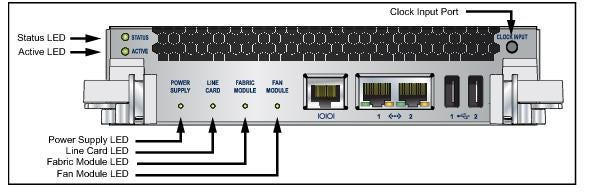
Figure A-2: Supervisor Module: 7508E / 7504E
Supervisor Activity Status LEDs
The Status and Active LEDs are located on the left side of the Supervisor Module. Table A-3 interprets the states of these two LEDs.
|
LED Name
|
LED State
|
Supervisor State
|
|
Status
|
Off
|
Module failed or is improperly inserted.
|
|
Green
|
Supervisor operating normally.
|
|
|
Red
|
Module failed.
|
|
|
Active
|
Off
|
Supervisor is not active.
|
|
Green
|
Supervisor is active and controlling the switch.
|
Component Activity Status LEDs
LEDs located below the vents and left of the input ports display summary indicators for power supplies, fabric modules, fan modules, and line cards. Table A-4 interprets the states of these indicators. When error conditions are indicated, refer to LEDs on the specified modules to determine the condition’s source.
|
LED Name
|
LED State
|
Module State
|
|
Power Supply,
Line Card Fabric Module |
Off
|
No modules are present or powered.
|
|
Green
|
All powered modules are operating normally.
|
|
|
Red
|
At least one module has failed.
|
|
|
Fan Modules
|
Amber
|
At least one fan is missing or has failed.
|
|
Green
|
All modules are operating normally.
|
|
|
Red
|
There are insufficient functional fans installed in the switch.
|
Line Card Module Indicators
Each line card module provides one status LED plus LEDs for each port on the card. The figures in Appendix E indicate the location of the LEDs on each line card. Figure A-3-left displays the status LED and Port LEDs on the left side of the DC-7548S-LC line card. Figure A-3-right displays the status LED and Port LEDs on the left side of the DCS-7500E-36Q-LC line card.
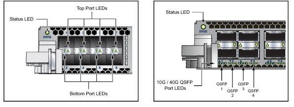
Figure A-3: line card Status LED
The line card Status LED is in the top left corner of the DC-7548S-LC line card. Table A-5 interprets the states of the Status LED.
|
LED State
|
Status
|
|
Off
|
line card not inserted.
|
|
Green
|
line card operating normally.
|
|
Yellow
|
line card administratively shut down.
|
|
Red
|
Module has failed.
|
The line card provides LEDs for each port module socket:
• Figure A-3-left displays SFP module LEDs. Each LED corresponds to a module.
• Figure A-3-right displays QSFP module LEDs. A set of four LEDs correspond to each module. When the module is programmed as a 40G port, the first LED in the set reports status. When the module is programmed as four 10G ports, each port is assigned to an LED within the set.
Table A-6 interprets the port LED states.
|
LED State
|
Status
|
|
Off
|
Port link is down.
|
|
Green
|
Port link is up.
|
|
Yellow
|
Port is disabled in software.
|
Fan and Fabric Status Indicators
Fan and Fabric Status LEDs are on fan modules (DCS-7508) or fan-fabric modules (DCS-7504, DCS-7508E, and DCS-7504E). Appendix D displays the position of these LEDs on the rear of each switch. Figure A-4 displays Fan Status and Fabric Status LEDs on the DCS-7508 and DCS-7504 switches.
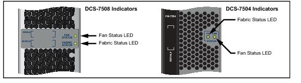
Figure A-4: Fan Status and Fabric Status LEDs
Table A-7 interprets the states of the Fan and Fabric Status LED.
|
LED State
|
Status
|
|
Off
|
Module inserted, but status is unknown.
|
|
Green
|
Module operating normally
|
|
Red
|
Module failed
|