Rear Panel
All switches covered by this guide use one of the rear panels shown below. Depending on the installed power supply module, the appearance could differ from those shown. Some of the PSUs have a velcro strap for cable management.
Note: Handle or bezel color indicates airflow direction.
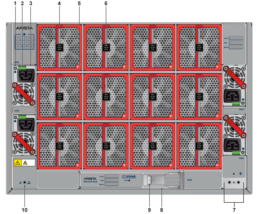
| 1 | PSU 1 status LED | 5 | Fan module 1 status LED | 9 | Supervisor card module release |
| 2 | PSU1 release | 6 | Fan module 2 release | 10 | ESD attach point |
| 3 | Power supply module 1 | 7 | Grounding | ||
| 4 | Fan module 1 | 8 | Supervisor card module access |
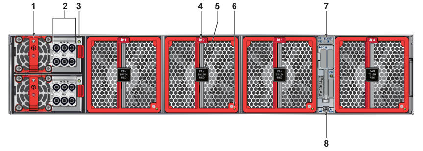
| 1 | Power supply module 1 | 4 | Fan module 2 | 7 | Supervisor card module access |
| 2 | PSU 1 connector | 5 | Fan module 2 release | 8 | ESD attach point |
| 3 | PSU 1 status LED | 6 | Fan module 2 status LED |