EVPN Overview
Ethernet VPN (EVPN) is a standards-based BGP control plane to advertise MAC addresses, MAC and IP bindings and IP Prefixes. This document focuses on EVPN and its operation with a VXLAN data plane for building overlay networks in the data center.
A number of control planes exist today for VXLAN, based on specific use cases, whether it be a requirement to integrate with an SDN overlay controller, or operate in a standards based flood and learn control plane model.
Current flood and learn models operate either with a multicast control plane, or ingress replication, where the operator manually configures the remote VTEPs in the flood list. Both of these are data-plane driven, that is, MAC’s are learned via flooding. In the IP multicast model MAC’s are learned in the underlay via flooding to an IP multicast group, while ingress replication (HER) floods to configured VTEP endpoints and no IP Multicast is required in the underlay.
The controller based solution with Cloud Vision eXchange (CVX), locally learned MAC’s are published to a centralized controller and these MAC’s are then programed to all participating VTEPs.
A controller-less BGP EVPN MAC learning is a standards-based control-plane (MP-BGP) is used to discover remote VTEPs and advertise MAC address and MAC/IP bindings in the VXLAN overlay, thus eliminating the flood and learn paradigms of the previously mentioned (multicast or HER) controller-less approaches. As a standards-based approach, the discovery and therefore the advertisement of the EVPN service models can inter-operate amongst multiple vendors.
This highlights an important and powerful advantage of BGP EVPN; that being, it is a single control plane for multiple data-plane encapsulations and defines both Layer 2 and Layer 3 VPN services. As network operators drive toward simplicity and automation, having one control plane protocol and address family for all data-planes and VPN services will prove extremely powerful.
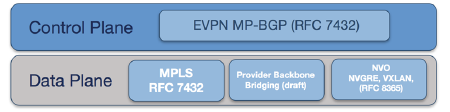
The initial EVPN standard is RFC 7432 defined the BGP EVPN control plane and specifies an MPLS data-plane. The control plane with an MPLS data plane was extended to consider additional data plane encapsulations models including VXLAN, NVGRE, and MPLS over GRE.
EVPN Terminology
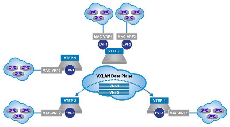
The EVPN standard, in the context of an NVO environment, defines the functionality for delivering multi-tenant Layer 2/3 VPN services using either VXLAN, NVGRE, or MPLS over GRE encapsulation across a common physical IP infrastructure. The standard introduces new terminology specific to a NVO environment, which is summarized below in relation to VXLAN encapsulation.
- Network Virtualization End-Point (NVE): The provider edge node within the NVO environment is responsible for the encapsulation of tenant traffic into the overlay network. For a VXLAN data plane, this defines the Virtual Tunnel End-Point (VTEP).
- Virtual Network Identifier (VNI): The label identifier within the VXLAN encapsulated frame, defining a Layer 2 domain in the overlay network.
- EVPN instance (EVI): A logical switch within the EVPN domain that spans and interconnects multiple VTEPs to provide tenant Layer 2 and Layer 3 connectivity.
-
MAC-VRF: A Virtual Routing and Forwarding table for storing Media Access Control (MAC) addresses on a VTEP for a specific tenant.
The new EVPN Network Layer Reachability Information (NLRI) is carried in BGP using Multi-protocol BGP Extensions with a newly defined Address Family Identifier (AFI) and Subsequent Address Family Identifier (SAFI).
To provide multi-tenancy, the standard uses the above traditional VPN methods to control the import and export of routes and provide support for overlapping IP address between tenants.
- EVPN Layer 2/Layer 3 tenant segmentation: Similar to standard MPLS VPN configurations Route Distinguisher's (RD’s) and Route Targets (RT’s) are defined for the VPN.
- Route Target (RT): To control the import and export of routes across VRFs, EVPN routes are advertised with Route-Target (RT) (BGP extended communities). The RT can be auto-derived to simplify the rule configuration; typically, this is based on the AS number and the VNI of the MAC-VRF.
- Route Distinguisher (RD): Unique number prepended to the advertised address within the VRF, ensuring support for overlapping IPs and MACs across different tenants.
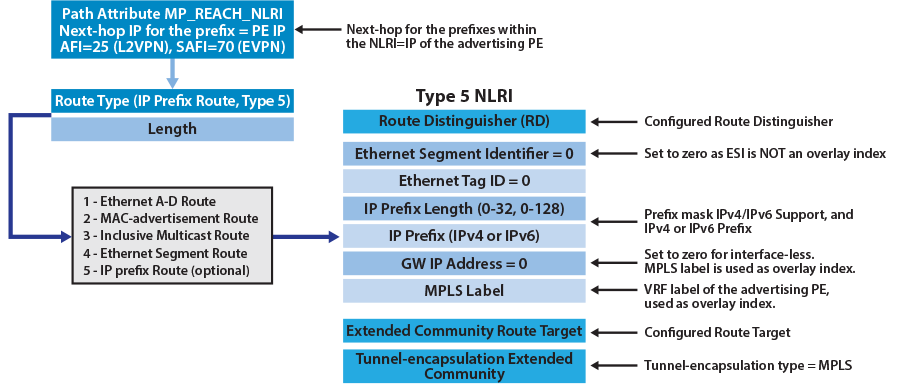
The format of the MP_REACH_NLRI/MP_UNREACH_NLRI attribute, holding the new EVPN NLRI is illustrated below, where the next-hop address within the NLRI is the IP address of the VTEP advertising the EVPN route.
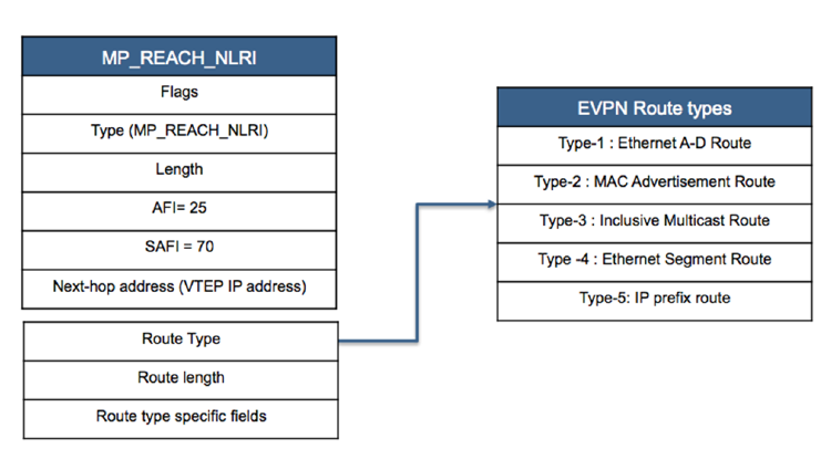
As illustrated, the original MPLS RFC (7348) and subsequent IP prefix draft (EVPN Terminology), introduce five unique EVPN route types.
Type-1 Route: Ethernet A-D route
Ethernet A-D route per ESI route, announces the reachability of a multi-homed Ethernet Segment. The route type is used for fast convergence (ie: ‘mass withdraw’) functions, as well as split horizon filtering used for active-active multi-homing.
Ethernet A-D route per EVI route, is used to implement the Aliasing and Backup Path features of EVPN associated with active-active multi-homing.
Type-2 Route: Host advertisement Route
Used to advertise the reachability of a MAC address, or optionally a MAC and IP binding as learned by a specific EVI. With the advertisement of the optional IP address of the host, EVPN provides the ability for VTEPs to perform ARP suppression and ARP proxy to reduce flooding within the Layer 2 VPN.
Type-3 Route: Inclusive Multicast route
The type-3 route is used to advertise the membership of a specific Layer 2 domain (VNI within the VXLAN domain), allowing the dynamic discovery of remote VTEPs in a specific VNI and the population of a VTEP ingress flood list for the forwarding of Broadcast Unknown unicast and Multicast (BUM) traffic.
Type-4 Route: Ethernet Segment Route
The type-4 route is specific to VTEPs supporting the EVPN multi-homing model, for active-active and active-standby forwarding. The route is used to discover VTEPs which are attached to the same shared Ethernet Segment. Additionally, this route type is used in the Designated Forwarder (DF) election process.
Type-5 Route: IP-prefix route advertisement
The type-5 route is used to advertise IP prefixes rather the MAC and IP hosts addresses of the type-2 route. This advertisement of prefixes into the EVPN domain provides the ability to build classic Layer 3 VPN topologies.
A detailed understanding of the function of each of these route types in the operation of EVPN to provide multi-tenant Layer 2 and 3 VPN services, is defined in Section 4 of this document.
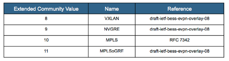
While this guide focuses on EVPN with VXLAN data-plane encapsulation, it’s important to note that, in addition to the new routes type, a BGP encapsulated extended community is included in all advertisements to determine the data-plane encapsulation.
The Encapsulation extended community is defined in RFC 5512. The different IANA registered tunnel types for an NVO environment are summarized in the table below.
EVPN Service Models
An EVPN Instance (EVI), can contain, one or more Layer 2 broadcast domains (VLANs).
Three EVPN service models—VLAN-based, VLAN bundle, and VLAN aware bundle—define the association of VLAN IDs to a specific EVI instance and how a VLAN tag can be transported within the EVI if required.
VLAN Based Service Interface
In the VLAN-based service there is a one-to-one mapping between the VLAN-ID and the MAC-VRF of the EVPN instance. With the MAC-VRF mapping directly to the associated VLAN, there will be a single bridge table within the MAC-VRF. The VLAN tag is not carried in any route update and the VNI label in the route advertisement is used to uniquely identify the bridge domain of the MAC-VRF in the VXLAN forwarding plane.
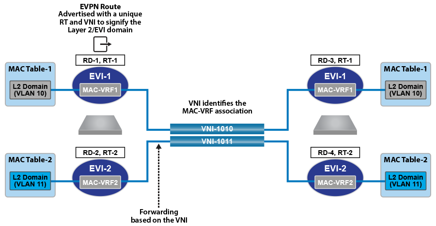
With a one-to-one mapping between the VLAN-ID and the MAC-VRF of the EVI instance, the EVI will represent an individual tenant subnet/VLAN in the overlay. The one-to-one mapping also means the route-target associated with the MAC-VRF, uniquely identifies the tenant’s subnet/VLAN, providing granular importing of MAC routes on a per VLAN basis on each VTEP.
In this service, the associated MAC-VRF table is identified by the Route-Target in the control plane and by the VNI in the data plane and the MAC-VRF table corresponds to a single VLAN bridge domain.
VLAN Bundle Service Interface
In the VLAN bundle service, there is a many-to-one mapping between the VLAN-IDs and the MAC-VRF of the EVPN instance. The MAC-VRF, however, only contains a single Layer 2 bridge table and VNI label. Thus MAC addresses must be unique across all associated VLANs.
With the MAC-VRF containing a single Layer 2 bridge table and a single VNI, the original VLAN tag has no significance in the control plane and is not carried in any EVPN route update. The original Ethernet tag and the VNI label are carried in the VXLAN data plane, to allow forwarding to the correct tenant VLAN.
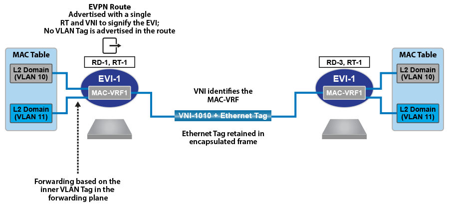
In this service, the Route-Target associated with the MAC-VRF identifies the tenant rather than an individual subnet/VLAN of a tenant. This means all MAC routes for the tenant will be imported on the VTEP regardless of whether or not the specific tenant VLAN exists. The MAC-VRF table is identified by the Route-Target in the control plane, and forwarding to the appropriate tenant VLAN is achieved via a combination of the VNI and Ethernet tag in the VXLAN data plane.
VLAN Aware Bundle Service Interface
In the VLAN aware bundle service, there is a many-to-one mapping between the VLAN-IDs and the MAC-VRF of the EVPN instance. However, the MAC-VRF contains a unique Layer 2 bridge table for each associated VLAN-ID and a unique VNI label for each bridge domain.
With the MAC-VRF containing multiple Layer 2 bridge tables, the VLAN tag is carried in any EVPN route update to allow mapping to the correct tenant bridge table within the MAC-VRF. Only the unique VNI label is carried in the VXLAN data plane, to allow forwarding to the correct VLAN with the MAC-VRF.
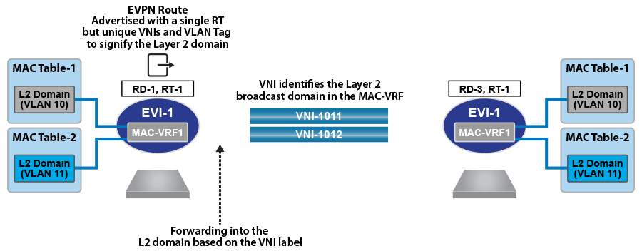
In this service, the MAC-VRF of the EVI instance represents multiple subnet/VLANs of the tenant. The Layer 2 bridge table of the MAC-VRF is identified by a combination of the Route-Target and the Ethernet tag in the control plane and by the unique VNI in the VXLAN data plane.
This service type is a common DCI/WAN deployment, where a tenant’s VLANs are bundled into single EVI instance. At the same time, VLAN “awareness” can be retained in the EVPN service as the VNI tag is advertised in the MAC-IP route (which now identifies the VLAN within the EVI). Bundling into a service like this reduces the number of EVI’s that need to be configured, reducing complexity and the control-plane signaling between PE’s.
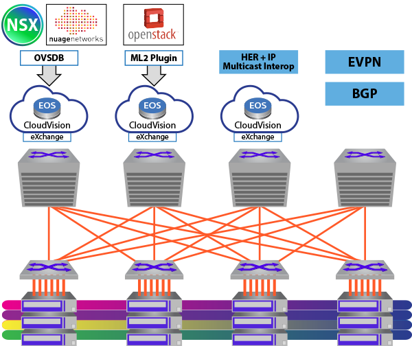
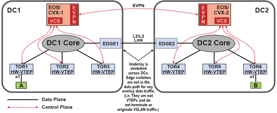
VCS and EVPN in DCI
When VXLAN Control Services (VCS) is enabled on a CloudVision eXchange (CVX) of a Data Center (DC), each VXLAN Tunnel End Point (VTEP) connects to the corresponding CVX to share the Layer 2 bridging information of its attached hosts. In turn, CVX advertises this information to all VTEPs within the DC.
- Receives the local Layer 2 bridging information in CVX control plane format from all VTEPs within the DC, and advertises it to remote CVXs in the BGP-EVPN NLRI format.
- Receives the Layer 2 bridging information in BGP-EVPN NLRI format from remote
CVXs, and advertises it to local VTEPs in the CVX control plane
format.Note: The distribution of Layer 2 bridging information as described above, allows a Layer 2 overlay network to be stretched across multiple DCs without additional VTEP configurations.
The following graphic illustrates the federation of CVX across multiple DCs.
EVPN MPLS LAYER 3 VPN (Type-5 Route)
Ethernet VPN (EVPN) is an extension of the BGP protocol introducing a new address family: Layer 2 VPN (address family number 25) / EVPN (subsequent address family number 70). It is used to exchange overlay MAC and IP address reachability information between BGP peers using type-2 routes. Additionally, EVPN supports the exchange of layer 3 IP overlay routes through the extensions described in (type 5 EVPN routes).
An IP VRF is used on a PE router for each Layer 3 overlay. VRF IP routes are exported into the EVPN BGP table and advertised to remote VTEPs as type 5 routes. The exported EVPN routes carry the Route-Target (RT) extended communities that are configured as export route-targets on the IP VRF from which they were exported.
The RTs carried by the EVPN type 5 routes received by a PE are matched against the VRF import route-target configuration. When a received route carries an RT that is configured as an import route-target on an IP VRF, the route is imported into the IP table for that VRF.
PE routers allocate per-VRF and address family Labels that are advertised as part of the Layer 3 (type 5) EVPN route NLRI. Forwarding of overlay packets between PEs across the underlay requires underlay MPLS connectivity provided by an IP backbone.
The type-5 routes allows you to decouple the advertisement of an IP prefix from any specific MAC address, support floating IP addresses, optimize the mechanism for advertising external IP prefixes, and reduce the churn when withdrawing IP prefixes.
The format of the new type-5 IP-prefix route is illustrated in the figure below. Unlike VXLAN, whichis used as a transport, BGP route update for MPLS does not specify the router-mac extended community and sets the tunnel encapsulation to MPLS. Unlike with VXLAN encapsulation, which uses the VNI as the overlay index, the MPLS Type-5 route uses the MPLS label.
The following example offers a more detailed view of the route as displayed on a PE router.
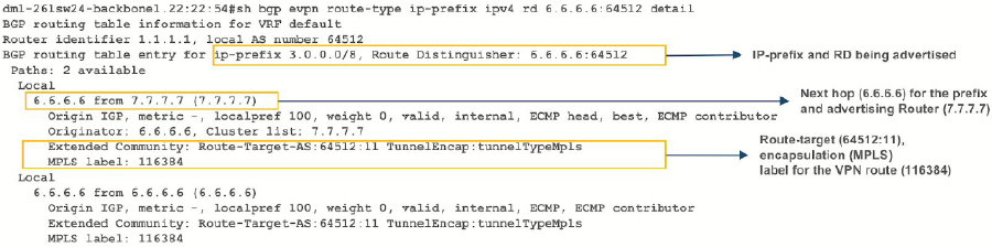
As shown in the example, the route contains the VPN route (prefix and RD), the next-hop for the route and the advertising router ID, along with the extended communities of tunnel type (MPLS), MPLS Label value and route-target.
EVPN VXLAN IPv6 Overlay
Beginning with EOS Release 4.22.0F, the EVPN VXLAN L3 Gateway using EVPN IRB supports routing traffic from one IPv6 host to another IPv6 host on a stretched VXLAN VLAN.
iBGP as PE-CE Protocol for BGP and EVPN L3 VPNs
EOS supports iBGP as the Provider Edge (PE) - Customer Edge (CE) as an extension to BGP EVPN Layer 3 (L3) VPNs. The feature provides a method to isolate your network BGP attributes from a Service Provider (SP) backbone attributes by saving the your network BGP attributes into a special attribute called ATTR_SET, code 128. This separation introduces a route server model that allows your BGP attributes to be stored in the SP backbone along with the VPN IPv4 and IPv6 paths.
The configuration requires the Autonomous Systems (AS) numbers of the PE Virtual Router Forwarding (VRF) and the CE to match regardless of the VPN AS number on the default VPN. This causes the exported paths by the PE to carry your original attributes through the SP backbone in a new attribute, ATTR_SET, code 128. Any CE at a different site sees only your attributes except the next-hop. For better loop prevention and detection, EOS requires any iBGP-configured CE to be configured as a route-reflector client of the PE.
EOS does not restrict exporting and importing VRFs from different sites to sharing the same AS number. When configuring iBGP on the CE, this means that each CE has the same AS number as the VRF in the respective PE, and the AS numbers may be different. To address this issue, a peering relationship exists between exporting and importing VRFs in the SP network. The ATTR_SET, code 128 carries the AS number of the VRF that exported the paths and the relationship between the origin AS number and the AS number assigned to the VRF importing the paths controls the restoration of the original CE attributes. If the AS numbers do not match, EOS removes the iBGP-specific attributes and prepends the AS-path with the origin AS number, just as eBGP peering does.
- For export points, route-maps match your attributes and also applies them to the SP-VPN attributes.
- For import points, route maps match the SP-VPN attributes and applies them to the your restored attributes.