
Overview
VeloCloud SD-WAN is a cloud network service solution that allows sites to quickly deploy Enterprise-grade access to on-premises and cloud applications over both private networks and Internet broadband.
Cloud-delivered software-defined Wide Area Network (WAN)ensures enterprises have consistent cloud application performance over the Internet and hybrid WAN, while simplifying deployments and reducing costs.
The following figure and sections provide a detailed description of the VeloCloud SD-WAN solution components.
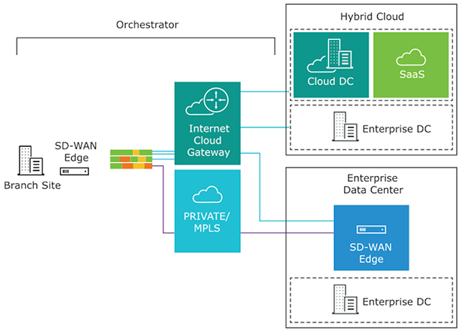
To become familiar with the basic configuration and Edge activation, see Activate Edges.
Arista VeloCloud SD-WAN Routing Overview
This section provides an overview of VeloCloud SD-WAN routing functionality, including route types, connected and static routes, and dynamic routes with tie-breaking scenarios and preference values in Overlay Flow Control (OFC) with Distributed Cost Calculation (DCC).
VeloCloud SD-WAN routing, built on a proprietary protocol called VCRP, supports multi-path capabilities and is secured through VCMP transport. The SD-WAN endpoints are connected using VCRP, similar to the iBGP full mesh. The SD-WAN Gateway acts as a Border Gateway Protocol (BGP) route reflector, reflecting routes from one SD-WAN Edge to another SD-WAN Edge within the customer's enterprise based on the profile settings.
The following diagram illustrates a typical SD-WAN deployment with Multi-Cloud non-SD-WAN destinations, where the Orchestrator performs the route calculation (as opposed to the newer and preferred method using Dynamic Cost Calculation (DCC).
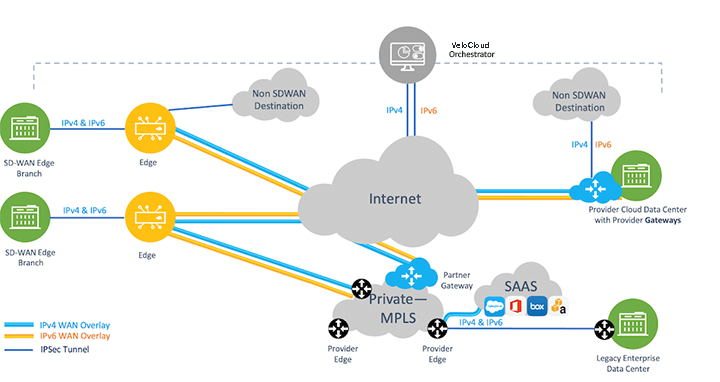
For information on route ordering in a full-mesh Hub-interconnect topology, see Route Ordering in a Full-Mesh Hub-Interconnect Topology.
SD-WAN Components for Routing Purposes
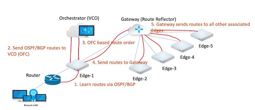
- The SD-WAN Edge is an Enterprise-class device or virtualized cloud instance that provides secure and optimized connectivity to private, public, and hybrid applications and virtualized services. In SD-WAN routing, the Edge is a Border Gateway. An Edge can function as a regular Edge (with no Hub configuration), a Hub by itself or as part of a cluster, or a spoke (with Hubs configured).
- The SD-WAN Gateway is autonomous, stateless, horizontally scalable, and cloud-delivered, allowing Edges from multiple tenants to connect. For any SD-WAN deployment, several SD-WAN Gateways are deployed as a geographically distributed network (for lower latency) and a horizontally scalable network (for capacity), with each Gateway acting as a Route-Reflector for In-band Telemetry and Shaping connected Edges. Edge sends all locally learned routes to the Gateway based on the configuration. The Gateway then reflects these routes to other Edges within the enterprise, allowing for efficient full-mesh Virtual Private Network (VPN) connectivity without building a full mesh of tunnels.
- The SASE Orchestrator is a multi-tenant cloud-based configuration and monitoring portal. In SD-WAN routing, the Orchestrator manages routes for all enterprises and can override default routing behavior.
Refer to the following image for an illustration of the VeloCloud SD-WAN components used for routing purposes.
Route Types
- Local Routes -Subnets learned locally by an SD-WAN Edge through a direct connection, static configuration, or dynamic protocols (BGP/OSPF).
- Remote Routes - Routes learned through the VeloCloud Router Protocol (VCRP). These originate from distant Edges and propagate through the Gateway to the rest of the enterprise.
Traffic routed based on a strict, non-alterable order of operations. While the sequence is fixed, users can influence flow using Longest Prefix Match (LPM), which always takes precedence over the route source.
- Longest Prefix Length - The most specific mask always wins.
- Local Connected - Directly attached interfaces.
- Local Static (Preferred) - If enabling the Preferred option (LAN Static > WAN Static). If disabled, Overlay routes take precedence.
- Local NSD Static - Local Non SD-WAN Destination routes (IPsec tunnels preferred over GRE).
- Remote NSD Static - NSD routes learned from other Gateways/Edges.
- Remote Edge Routes - Remote Connected followed by Remote LAN/WAN Static.
- Partner Gateway (PG) Static - Secure PG Static > Non-secure PG Static.
- Dynamic Routes - Managed by Overlay Flow Control (OFC) or Distributed Cost Calculation (DCC) Driven route order.
- Prefers Site Local (OSPF Inter/Intra, BGP non-uplink) over overly dynamic routes.
- Local OSPF inter/intra area routes win over Local BGP.
- Local BGP wins over Local OSPF-external (OE1/OE2).
- Remote routes with preferred cost win over non-preferred local route (OE1, OE2, UPLINK BGP).
- Within the remote dynamic routes preference is considered and the lower preference wins.
- If the preference is the same, BGP attributes and OSPF metrics compare to each other.
- OSPF INTRA> INTER > OE1 > OE2
- BGP
- Higher Local preference
- Lower AS_PATH Length
- Smaller BGP metric
For additional details on preference calculation, refer to the DCC section.
Connected and Static Routes
Configure a connected route for any network directly attached to the interface. Use static routes only for specific scenarios requiring fixed paths for network-attached devices, such as printers or legacy hardware. For additional information about static routes, see the Configure Static Route Settings section.
Requirements for Connected Route Visibility
- Activate Cloud VPN - Enable Cloud VPN to allow the route to participate in the overlay..
- Assign a Valid IP Address - Configure the connected route with a valid IP address.
- Verify Interface Status - Ensure the Edge interface remains physically up (Layer 1) and operationally functional (Layers 2 and 3).
- Maintain VLAN Integrity - VLANs associated with this Edge interface must be up.
- Enable Advertisement - Set the Advertise flag on the Edge interface under Interface IP settings to broadcast the route to the rest of the network.
- To ensure a static route is visible and functional within the SD-WAN overlay, users must Activate Cloud VPN and set the route to Advertised in the Orchestrator. Static routes direct traffic to either the WAN underlay or the LAN and automatically bypass NAT on the Edge interface.
- ECMP Support - VeloCloud support Equal-Cost Multi-Path (ECMP) for BGP, OSPF, and Static Routing on the Edges.
- Prevent Black-holing - Always configure an ICMP Probe. This ensures the Edge can detect a next-hop failure and avoid sending traffic into a black-hole.
- Priority Logic - A static route marked with a Preferred flag is ideal over any VPN route learned over the Overlay.
Route Configuration Flags - Preferred vs. Advertise
When configuring static routes, users must distinguish between the Preferred flag, which controls local path selection, and the Advertise flag, which controls global reachability.
- Preferred - The Preferred flag determines whether the Edge uses the static route or a learned VPN route for local traffic forwarding.
- Enable Preferred - The Edge prioritizes the static route over all other options. The system matches this route first, even if a lower-cost VPN route is available.
- Disable Preferred - The Edge treats the static route as a last resort, and uses any available VPN route, even those with a higher cost, and only fallback to the static route if the VPN routes disappear.
- Advertise - The Advertise flag controls how the network shares the static route.
- Enable Advertise - The Edge broadcasts the static route across the SD-WAN overlay (VCRP). This allows other SD-WAN Edges to access the resource. It also enables the redistribution of the static route into local routing protocols like BGP or OSPF.
- Disable Advertise - The route remains local to the specific Edge. Use this setting for private resources, such as personal printers, to prevent other users in the enterprise from accessing them.
- External OSPF Routes
- Non SD-WAN Destination (NSD) iBGP Routes
Hub and Branch Precedence
- The Edge ignores the Global Advertise Flags of the Hub profile.
- Instead, the Edge enforces the Global Advertise Flags configured for the Branch profile.
Internal Route Types - Self and Cloud Routes
The Edge installs two specialized route types, Self Routes and Cloud Routes, based on the specific configuration. These routes serve narrow, automated functions and require no manual adjustment.
Self Routes (Flag s)
Also known as Interface Routes, these refer to interface-based prefixes , for example, 172.16.1.10/32 that use Longest Prefix Match (LPM).
- Local Scope - The Edge installs these locally but does not advertise them to remote Edges.
- Connected Routes - While the Edge can advertise a Connected Route into the overlay to allow remote client access, it keeps Self Routes strictly local to the device.
Cloud Routes (Flag v)
- Internet Optimization - This route points to the Primary Gateway for multi-path Internet traffic. It ensures that Internet-bound data leverages Dynamic Multi-Path Optimization (DMPO) through the Gateway before reaching its destination.
- Management Traffic - The Edge also utilizes a Cloud Route through the corresponding Gateway to reach the Orchestrator on the public cloud.
Table 1. Comparison - Route Visibility Route Type Flag Scope Primary Purpose Self sLocal Only Interface Identification (LPM) Cloud vGateway Direct DMPO for Internet and Orchestrator management Connected cGlobal (if advertised) Client-to-client connectivity across the SD-WAN
Overlay Flow Control with Distributed Cost Calculation
Activation and Support
Existing Customers - VeloCloud recommends enabling DCC to optimize route calculations.
New Customers - Future releases automatically activate this feature for all new deployments.
For additional information about DCC, including best practices, refer to the topic Configure Distributed Cost Calculation in the Arista VeloCloud SD-WAN Operator Guide.
Distributed Cost Calculation Overview
Distributed Cost Calculation (DCC) shifts the responsibility for calculating route preferences from the SASE Orchestrator to the SD-WAN Edges and Gateways. Under this model, the Edge and Gateway insert routes immediately upon learning them and then communicate these calculated preferences back to the Orchestrator.
- Connectivity Gaps - An Edge or Gateway may lose contact with the Orchestrator, preventing it from receiving updated preferences.
- Processing Bottlenecks - The Orchestrator may struggle to deliver updates quickly when calculating a massive volume of routes simultaneously.
By distributing calculation tasks to the local Edges and Gateways, the system ensures fast, reliable, and resilient route updates across the entire enterprise.
Distributed Cost Calculation Preference Overview
| Edge | Partner Gateway / Hosted Gateway |
|---|---|
| NSD E BGP | NSD E/I BGP |
| NSD I BGP | E/I BGP |
| NSD Uplink BGP | |
| OSPF O | |
| OSPF IA | |
| E BGP | |
| I BGP | |
| OSPF OE1 | |
| OSPF OE2 | |
| Uplink BGP |
| O = OSPF Intra area |
| IA = OSPF Inter area |
| OE1 = OSPF External Type-1 |
| OE2 = OSPF External Type-2 |
| E BGP = External BGP |
| I BGP = Internal BGP |
| NSD = Non SD-WAN Destination |
Release 4.3.0 and later support Non SD-WAN Destination (NSD) support with Overlay Flow Control (OFC). For additional information on NSDs, see Configure a Non SD-WAN Destination.
The SD-WAN system assigns a preference value (or cost) to every route based on its type. The Edge uses these values to determine path priority: the lower the preference value, the higher the priority.
The Edge evaluates routes by comparing their default preference values. When the Edge learns multiple paths for the same prefix, it selects the route with the lowest numerical cost.
The system always favors a route with a preference of 10 over a route with a preference of 20. Orchestrator applies these default values globally to ensure predictable routing behavior across all Edges in the enterprise. While the system provides defaults, users can manually adjust costs within the Overlay Flow Control (OFC) to influence specific traffic flows.
| Device | Route Type | Default Preference |
|---|---|---|
| Edge/Hub | NSD E BGP | 997 |
| Edge/Hub | NSD I BGP | 998 |
| Gateway | NSD E/I BGP | 999 |
| Edge/Hub | NSD Uplink BGP | 1000 |
| Edge/Hub | OSPF O | 1001 |
| Edge/Hub | OSPF IA | 1002 |
| Edge/Hub | E BGP | 1003 |
| Edge/Hub | I BGP | 1004 |
| Partner Gateway | E/I BGP | 1005 |
| Edge/Hub | OSFP OE1 | 1001006 |
| Edge/Hub | OSPF OE2 | 1001007 |
| Hub/Edge | BGP Uplink | 1001008 |
- The Edge or Gateway learns a dynamic route from a local or remote neighbor.
- SD-WAN identifies the route type and retrieves the associated default preference value.
- SD-WAN assigns the appropriate preference value and installs the route into the Routing Information Base (RIB) and Forwarding Information Base (FIB).
- The system evaluates the default advertising action for the route. Based on this configuration, it performs one of two actions:
- Advertised - It broadcasts the route across the entire enterprise.
- Not Advertised - It keeps the route local to the RIB and FIB and takes no further action.
- The Edge synchronizes the route data with the Orchestrator, which then displays the route in the management console.
Preferred VPN Exit Points
This section explains how to configure Preferred VPN Exit Points, categorize routes, and use route pinning to override default system values.
Accessing the Configuration
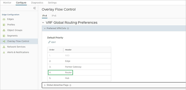
- Navigate to .
- Locate the Preferred VPN Exits.
- Identify Default Priorities - View the pre-configured hierarchy for different route types.
- Implement Route Pinning - Manually override the default preference values to force traffic through a specific gateway or exit point.
- Categorize Traffic - Assign routes to specific groups to simplify global management across the enterprise.
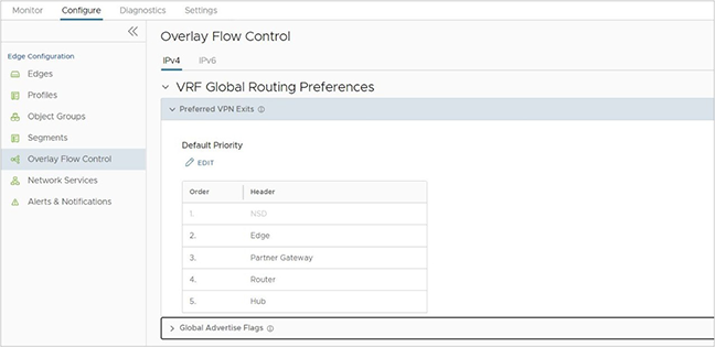
- Edge (Highest Priority) - The system assigns this category to any internal route learned on a Hub or Spoke Edge. Internal routes exclude OSPF E1/E2 or BGP Uplink types. The Edge marks these routes with the highest priority by default.
- Hub - Any external Route learned on an Edge/Hub falls into the Hub category and typically receives a lower priority. Hub routes include OSPF OE1/2 and BGP Uplink.
- Partner Gateway - Any route learned on a Partner Gateway.
- Router (The Preference Pivot) - The Router category represents the dynamic prefixes an Edge learns via BGP or OSPF. It acts as a threshold to determine the preference value for all dynamic routes.
- Above the Router - The system assigns a low preference value (preferred cost) to any exit point positioned above the Router, making these routes more preferred.
- Below the Router - The system assigns a high preference value to any exit point positioned below the Router, making these routes less preferred.
DCC Preference Example
- Preferred - Exit points above the Router, for example, an Edge, NSD, or Partner Gateway, receive a preference value less than 1,000,000.
- Less Preferred - Exit points below the Router (e.g., Hub) receive a preference value greater than 1,000,000.
Pinning a Route to Override a Default Preference Value
SD-WAN provides a Route Pinning feature that allows overriding the default preference value assigned to any dynamic route. After learning a dynamic route and synchronizing with the Orchestrator, navigate to the Overlay Flow Control page and override the default order for that route.
Pin a route on the Overlay Flow Control page using one of the following options:
- On the Routes List, select one or more routes and then select Pin Learned Route Preference.
- Modify the order of the Preferred VPN Exits by selecting Edit.
- The Orchestrator sends this routing event to the relevant Edges in the customer enterprise.
- The Edges override the previous preference value to match the pinned order.
- The preference values assigned to pinned routes start from 1, 2, 3, the lowest values, and thus the highest preferences. This matches the order of the routes on the Overlay Flow Control page. For more information on pinning a route, see Configure Subnets.
Tie-Breaking Scenarios for All Types of Routes
In some SD-WAN deployments, two different Edges or Partner Gateways may advertise the same prefix. When these subnets share the same category, Edge, Hub, or Partner Gateway, and preference value, VeloCloud SD-WAN applies a specific hierarchy to resolve the conflict.
- Protocol Attributes - The system first evaluates the BGP attributes or OSPF metrics. The route with the better protocol metric wins.
- Logical ID (LID) - If a tie remains, SD-WAN uses the Logical ID (LID) of the next-hop device to break it. The system derives this LID from the device’s Universally Unique Identifier (UUID).
- Branch-to-Branch via Gateway - The Gateway provides the next-hop LID.
- Branch-to-Hub - The Hub Edge provides the next-hop LID.
Note: Administrators cannot control or change how the system generates an LID. The system compares LIDs using an internal algorithm that evaluates four distinct data blocks. For example, the algorithm may determine that
lid1-data1is greater thanlid1-data2.
- Route Age (Final Tie-Breaker) - If multiple Gateways advertise the same route type and preference, the system applies one final tie-breaker - it prefers the oldest learned route.
Influencing the Outcome
- Route Pinning - Manually pin specific routes to force a preferred path.
- Metric Configuration - Adjust BGP attributes (such as Local Preference) or OSPF costs to favor specific routes before the system reaches the LID tie-breaker.
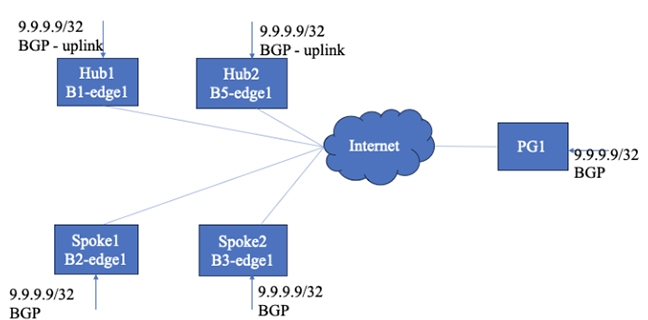
9.9.9.9/32, creating a path-selection challenge.
- Spokes - Both Spoke1 and Spoke2 learn the route as non-uplink BGP routes.
- Hubs - Hub1 and Hub2 learn the routes as uplink BGP routes.
- Partner Gateway - PG1 also learns the same route.
Connectivity Configuration
The Spoke Profile currently enables Branch-to-Branch communication through both Hub1 and Hub2. This configuration forces the system to evaluate which Hub provides the optimal path for inter-spoke traffic destined for the 9.9.9.9/32 prefix.
Route Ordering on Spokes with Non-uplink Routes
- Because Spoke1 and Spoke2 learn the route through BGP, they assign a preferred cost of 1003 based on the DCC preference mapping table. The Spokes process the route as follows:
- FIB Installation - Spoke1 and Spoke2 install the
9.9.9.9/32route into their Forwarding Information Base (FIB) with a reference cost of 1,000,000. - Underlay Handling - As standard behavior, the system installs the underlay route in the FIB using only this reference cost.
- Route Sorting - The system uses the derived cost from the DCC preference table to sort routes learned from remote SD-WAN entities, such as other Edges or Gateways.
- FIB Installation - Spoke1 and Spoke2 install the
- After learning and installing the route, Spoke1 and Spoke2 redistribute it using the VeloCloud Router Protocol (VCRP). They broadcast the route to the Gateway and remote Hubs/Edges using the derived cost of 1003.
Figure 7. Derived Cost or Preference in Spokes 
- Similarly Hub1 and Hub2 learn the route and derive the non-preferred cost 1,001,008, since they receive the advertisement through an uplink. The Hubs then redistribute this route to the Gateways and other Edges using this specific cost.
Figure 8. Derived Cost or Preference in Hubs 
- PG1 learns the same route from BGP, uses cost 1005, and redistributes it to the Edges. The output displays the derived cost/preference in PG1.
Figure 9. Derived Cost or Preference in PG1 
- Comparing Local Underlay vs. Hub Routes - Spoke1 receives the route from Hub1 and Hub2 with a non-preferred cost of 1,001,008. However, Spoke1 maintains its local underlay route with a preferred cost of 1,003.
- Winner - Spoke1 prefers the underlay route.
- Spoke1 receives a route from Spoke2 and PG1 with costs 1003 and 1005, respectively. Since Spoke1 is having preferred cost 1003, and receives routes from Spoke2 and PG1 with a preferred cost (<100000), Spoke1 adds the reference cost 1000000 to the incoming preferred cost and installs the routes in FIB. In this case, Spoke2 route installs with a cost of 1001003 and the PG1 route installs with a cost of 1001005.
Figure 10. Install Routes 
- Spoke2 and the Hubs apply this same route-sorting logic if they learn the route as a non-uplink route.
- If no entity learns an underlay route, the system does not apply any corrections to the received route preference or cost. Instead, the Edge or Hub installs the routes exactly as they appear in the received preference and cost values.
Route Ordering on a Hub with Uplink Routes
When a Hub processes uplink routes, it follows a specific hierarchy to install and prioritize entries in the Forwarding Information Base (FIB).
- The Hub installs a local underlay route (SB) into the FIB using a base reference cost of 1,000,000.
-
The Hub receives routes from multiple spokes, each carrying a preferred cost of 1,003. To differentiate between these identical costs, the Hub applies the following tie-breakers:
- BGP Attribute Comparison - The Hub first compares BGP attributes and sorts the routes based on those metrics.
- Logical ID (LID) Comparison - If the BGP attributes match, the Hub uses the Spoke Logical ID to break the tie. The route from the Spoke with the lower destination Logical ID wins.
- FIB Entry - After resolving these ties, the Hub installs the spoke routes using the original received cost.
- The Hub receives routes from PG1 with a preferred cost. Because this is a preferred entry, the Hub installs the route into the FIB using that specific cost value without additional modification.
Figure 11. PG1 Route on the Hub 
Route Ordering on PG1
When managing routes, PG1 follows a streamlined priority logic based on direct preference values without applying the cost corrections found in standard Edges.
- PG1 installs its local underlay route (PB) into the Forwarding Information Base (FIB) with a fixed preference of 100,000.
- PG1 receives routes from Spokes and Hubs, each carrying their respective preference values. The system handles these as follows:
- Preference Matching - PG1 places routes in the FIB according to their numerical preference value.
- Protocol Tie-Breaking - If preference values match, PG1 evaluates BGP attributes to determine the winner.
- Logical ID (LID) Tie-Breaking - If the BGP attributes are also identical, PG1 uses the Logical ID to sort the routes and break the tie.
- Unlike standard SD-WAN Edges, PG1 does not perform preference or cost correction. It installs all incoming routes using the exact values it receives from the network.
-
Figure 12. No Preference or Cost Correction 
Behavior Without DCC Enabled
- If users do not enable Distributed Cost Calculation (DCC), the Orchestrator handles all advertisement verdicts and preference calculations. This centralized model requires constant communication between the devices and the Orchestrator
The Orchestrator-Driven Workflow
- Reporting - Each Edge or Gateway sends its learned routes to the Orchestrator.
- Calculation - The Orchestrator calculates the preference and determines if the route should be shared.
- Response - The Edge or Gateway waits for the Orchestrator to reply.
- Redistribution - Once the device receives a reply containing an Advertise Flag, True, it begins redistributing the routes to other SD-WAN entities.
- Preference Values and Sorting - While the general route ordering remains identical to the DCC model, the specific preference values change:
- The Reference Threshold - The Orchestrator uses 512 as the base reference cost.
- Preferred Routes - The system assigns a value less than 512 to preferred routes, for example, a non-uplink.
- Non-Preferred Routes - The system assigns a value greater than 512 to non-preferred routes, such as Uplink or OSPF External routes.
- Tie-Breaking and Comparison - The Orchestrator evaluates routes dynamically as it learns them:
- Initial Assignment - If Spoke2 reports a route first as non-uplink, the Orchestrator might assign it a preference value of 64.
- Relative Comparison - When Spoke1 subsequently reports the same route, the Orchestrator compares the entity, route type, and attributes. For better routes, Orchestrator then assigns a value lower than 64 or higher than 64 for worse routes.
- Hub Handling - When Hubs report uplink routes, the Orchestrator assigns a non-preferred cost (e.g., 4096). If two Hub routes carry the same preference, the Hub order determines the final sorting in the spokes.
Figure 13. Disable DCC and Route Order in Spoke1 without an Uplink Route 
- The router order in Hubs with an uplink route has the following format:
Figure 14. Router Order in Hubs with an Uplink Route 
- The route order in PGhas the following format:
Figure 15. Route Order in PG 
Route Ordering in the Gateway
The Gateway follows a strict hierarchy to determine route precedence. Unlike an Edge, the Gateway does not perform auto-correction on preferences. It installs dynamic routes using the exact preference value it receives.
Gateway Route Hierarchy (Highest to Lowest)
-
Longest Prefix Length - The most specific subnet mask always takes precedence.
- Local NSD Static Routes - Static routes for locally connected Non SD-WAN Destinations.
-
Remote NSD Static Routes - NSD routes learned from remote entities.
- Partner Gateway (PG) Secure Static - Enterprise-level PG static routes win over Global-level PG static routes.
- Remote Connected/Static Routes - When multiple remote Edges provide the same route, the Gateway uses the Edge Logical ID as a tie-breaker. In this specific Gateway logic, the higher Logical ID wins.
- Dynamic Routes (OFC/DCC) - The system sorts dynamic routes based on their preference value. The lower preference value wins. The Gateway installs local routes with a reference preference of 1,000,000.
- PG Non-Secure Static - Standard static routes from Partner Gateways.
- Edge Profile Settings - Configuration parameters defined at the profile level.
- Flow Direction - Whether the traffic moves North-South or East-West.
- DCC Status - How the Distributed Cost Calculation influences the incoming metadata.
Dynamic Multipath Optimization (DMPO)
This section provides an in-depth overview of Dynamic Multipath Optimization (DMPO) as used by the VeloCloud SD-WAN service.
Overview
VeloCloud SD-WAN enables enterprises and service providers to utilize multiple WAN transports simultaneously. By aggregating diverse links, the solution increases available bandwidth and ensures consistent application performance for both on-premises and cloud-based (SaaS/IaaS) environments.
The platform leverages a Cloud-Delivered architecture to construct a secure overlay network using multiple tunnels. This architecture continuously monitors and adapts to WAN transport fluctuations in real time.
Dynamic Multipath Optimization (DMPO)
- Continuous Monitoring - Tracks jitter, packet loss, and latency on every path.
- Automatic Steering - Moves traffic to the best available link based on application requirements.
- On-Demand Remediation - Applies error correction to maintain session quality during brownouts.
The following diagram depicts a typical SD-WAN deployment with Multi Cloud Non SD-WAN Destinations.
Key Functionalities
- Enterprise Connectivity (Branch-to-Branch or Branch-to-Hub) - Individual Edges establish direct DMPO tunnels with one another to facilitate secure, high-performance internal communication.
- Cloud Application Access - Each Edge creates DMPO tunnels with one or more Gateways to optimize paths for SaaS, IaaS, and other cloud-based resources.
Continuous Monitoring
Automated Bandwidth Discovery- After the VeloCloud Edge detects a WAN link, it immediately initiates the Automated Bandwidth Discovery process to calibrate the link for optimal performance.
- Tunnel Establishment - The Edge establishes DMPO tunnels with one or more VeloCloud Gateways.
- Bandwidth Testing - The Edge runs a bandwidth test with the nearest Gateway by sending short bursts of bidirectional traffic. The system measures the arrival rate at both ends to calculate the actual capacity.
- Public IP Identification: - Because the system deploys Gateways at Internet Points of Presence (PoPs), the Gateway identifies the WAN link true public IP address, even if the Edge sits behind a NAT or PAT device.
- Private Link Processing - The Edge applies this same discovery process to private links to ensure consistent performance data.
Hub and Headend Configurations
- Static Definition - The Orchestrator requires static WAN bandwidth definitions for Edges acting as Hubs or headends.
- Branch-to-Hub Testing When a Branch Edge establishes a DMPO tunnel with a Hub Edge, the devices execute the same bandwidth test procedures used between an Edge and a Gateway on a public link.
Continuous Path Monitoring
Dynamic Multipath Optimization (DMPO) performs continuous, unidirectional measurements of performance metrics-loss, latency, and jitter of every packet, on every tunnel between any two DMPO endpoints, Edge or Gateway.
Per-Packet Steering
VeloCloud SD-WAN utilizes per-packet steering to make independent routing decisions for both uplink and downlink directions. This granular control allows the system to optimize performance without introducing asymmetric routing issues.
Monitoring Methodologies
- Passive Monitoring (With User Traffic) - When user traffic flows through the network, DMPO inserts sequence numbers and timestamps into the tunnel header. These metrics enable the endpoints to identify lost or out-of-order packets and calculate bidirectional jitter and latency. The endpoints exchange these performance metrics every 100 ms.
- Active Monitoring (Without User Traffic) - If the network carries no user traffic, the system sends active probes every 100 ms. After five minutes of inactivity with no high-priority user traffic, the system reduces the probe frequency to 500 ms.
These comprehensive measurements allow DMPO to react instantly to fluctuating WAN conditions. By constantly evaluating link health, the system delivers sub-second protection against sudden outages or drops in bandwidth capacity.
MPLS Class of Service (CoS)- When users deploy a private link with a CoS agreement, configure DMPO to incorporate CoS tags into monitoring and application steering decisions. By recognizing these tags, the system ensures that the provider priority queues align with the SD-WAN routing logic.
Dynamic Application Steering
Application-aware Per-packet Steering - Dynamic Multipath Optimization (DMPO) identifies traffic using Layer 2 through Layer 7 attributes, such as VLAN, IP address, protocol, and specific applications. VeloCloud SD-WAN performs per-packet steering based on business policy configurations and real-time link conditions.
The system includes Smart Defaults out-of-the-box, which pre-configure steering behavior and priorities for more than 2,500 applications. This allows users to leverage dynamic steering and prioritization immediately without manually defining policies.
- Outage - The link fails completely and cannot pass traffic.
- Brownout - The link remains active but fails to deliver the required SLA for latency, jitter, or loss on a specific application.
VeloCloud SD-WAN provides sub-second protection against both conditions. By continuously monitoring all WAN links, DMPO detects an SLA failure or outage within 300–500 ms. It immediately steers the flow to a healthy link to maintain performance. Once the link stabilizes, the system observes a one-minute hold time before steering the traffic back to the preferred link.
- Internet Breakout - Redirecting traffic such as Netflix directly to the local Internet link to bypass the DMPO tunnel.
- Backhauling - Routing sensitive traffic like Office 365 to a regional hub or data center.
Real World Example - Skype for Business
- Initial State - If Link A has 50 ms latency and Link B has 60 ms, DMPO selects Link A.
- The Shift - If Link A suddenly experiences a brownout with 200 ms latency, DMPO detects the change in under one second. It immediately steers the Skype for Business packets to Link B to ensure the call remains clear and uninterrupted.
- Real-Time Path Selection - DMPO evaluates the current performance of every WAN link and decides which specific paths should carry the individual packets of a flow.
- Resequencing - To prevent the out-of-order packets often caused by multi-path load balancing, the receiving DMPO endpoint performs resequencing before delivering the traffic to the final destination.
- Hierarchical QoS - The system applies Quality of Service (QoS) policies at both the individual link level and the total aggregate level.
For example, two 50 Mbps links deliver 100Mbps of aggregated capacity for a single traffic flow and applies QoS at both the aggregate and individual link level.
If a site has two 50 Mbps links, DMPO can aggregate them to deliver 100 Mbps of total capacity for a single traffic flow. This ensures that a single large file transfer can consume the combined bandwidth of all transports rather than being limited to the speed of one link.
On-demand Remediation
Error and Jitter Correction - In a scenario where it may not be possible to steer the traffic flow onto the better link, such as a single link deployment, or multiple links with issues at the same time, DMPO can enable error corrections for the duration of the WAN link issues. The type of error corrections used depends on the type of applications and the type of errors.
Real-time applications such as voice and video flows can benefit from Forward Error Correction (FEC) when packet loss occurs. DMPO automatically enables FEC on single or multiple links. With multiple links, DMPO selects up to two of the best links at any given time for FEC. Duplicated packets are discarded and out-of-order packets are re-ordered at the receiving end before delivering to the final destination.
DMPO enables jitter buffer for the real-time applications when the WAN links experience jitter. TCP applications such as file transfer benefit from Negative Acknowledgement (NACK). Upon the detection of a missing packet, the receiving DMPO endpoint informs the sending DMPO endpoint to retransmit the missing packet. Doing so protects the end applications from detecting packet loss and, as a result, maximizes TCP window and delivers high TCP throughput even during lossy condition.
- Transactional/Bulk traffic- In this case, VeloCloud applies a NACK based retransmit algorithm, performed at the VCMP protocol level, and attempts to correct the error condition before handing over the packet to the application.
- Realtime traffic- In this case, VeloCloud applies adaptive FEC to replicate packets activated or deactivated upon loss SLA violation and jitter buffer correction upon jitter SLA violation – this can only be activated and persists for the life of the flow).
Orchestrator monitors and measures the link SLA (loss, latency, jitter) on a periodic basis and FEC (packet duplication) activates upon threshold violation for real-time traffic using different values for voice and video applications.
In a single WAN link scenario, duplicate packets transmit on the same link adjacent to one another. Since packet drops due to congestion are random, it is statistically unlikely that two adjacent packets drop, greatly increasing the likelihood that one of the packets makes it to the destination. The replicated packets are sent on separate links in the case of two or more WAN links.
Adaptive FEC triggers on a per-flow basis in real-time based on measured packet loss thresholds, and disabled in real-time after the packet loss no longer exceeds the activation threshold. This ensures that the network efficiently uses available bandwidth , avoids unnecessary packet duplication, and reducesresource overhead. The VeloCloud Adaptive FEC approach ensures minimal or elimination of the effect of packet loss on the transport network on end-user devices. When end-user devices do not see packet drops, the devices avoid retransmissions and TCP congestion avoidance mechanisms like slow start, which can negatively impact overall throughput, application performance, and end-user experience.
DMPO Real World Results
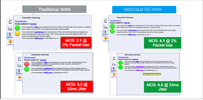
Scenario 1 - A Branch-to-Branch VoIP call uses a single link. The results in the figure demonstrate the benefits of on-demand remediation using FEC and jitter remediation on a single Internet link with traditional WAN and VeloCloud SD-WAN. A mean opinion score (MOS) of less than 3.5 is unacceptable quality for a voice or video call.
Scenario 2- TCP Performance with and without VeloCloud SD-WAN for Single and Multiple Links. These results show how NACK enables per-packet load balancing.

Scenario 3- Hybrid WAN scenario with an outage on the MPLS link and both jitter and loss on the Internet link. These results show how DMPO protects applications from sub-second outages by steering the traffic to Internet links and enabling on-demand remediation on the Internet link.

Business Policy Framework and Smart Defaults
The business policy lets the IT administrator control QoS, steering, and services for the application traffic. Smart Defaults provides a ready-made business policy that supports over 2500 applications. DMPO makes steering decisions based on the type of application, real time link condition (congestion, latency, jitter, and packet loss), and the business policy.
Each application has a category. Each category has a default action, which is a combination of Business Priority, Network Service, Link Steering, and Service Class. Users can also define custom applications.
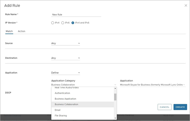
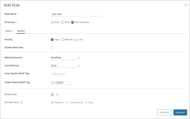
Each application has a Service Class: Real Time, Transactional, or Bulk. The Service Class determines how DMPO handles the application traffic. Users cannot change the Service Class for the default applications, but can specify it for their own custom applications.
Each application also has a Business Priority: High, Normal, or Low. The Business Priority determines how DMPO prioritizes and applies QoS to the application traffic. Users can change the Business Priority for any application.

- Direct- Typically used for non-critical, trusted Internet applications that should be sent directly, bypassing the DMPO tunnel, for example, Netflix. Netflix is considered a non-business, high-bandwidth application and the network should not send it over the DMPO tunnels. The traffic sent directly can be load balanced at the flow level. By default, all the low priority applications receive the Direct action for Network Service.
- MultiPath- Typically applied to important applications. By inserting the Multipath service, is sent to the VeloCloud Gateway sends the Internet-based traffic. The table shows the default link steering and on-demand remediation technique for a given Service Class. By default, high and normal priority applications receive the Multipath action for Network Service.
- Internet Backhaul- This action redirects the Internet applications to an enterprise location that may or may not have the VeloCloud Edge. The typical use case is to force important Internet applications through a site that has security devices such as firewall, IPS, and content filtering before the traffic is allowed to exit to the Internet.
Link Steering Abstraction With Transport Group
Across different branch and hub locations, there may be different models of the VeloCloud Edge with different WAN interfaces and carriers. In order to enforce the centralized link steering policy using Profile, it is important that the interfaces and carries are abstracted. Transport Group provides the abstraction of the actual interfaces of the devices and carriers used at various locations. The business policy at the Profile level can be applied to the Transport Group instead, while the business policy at the individual Edge level can be applied to Transport Group, WAN Link (carrier), and Interfaces.
Link Steering by Transport Group
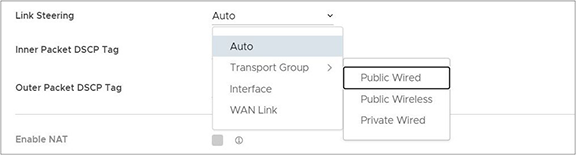
Different locations may have different WAN transports, such as a WAN carrier name or a WAN interface name, DMPO uses the concept of transport group to abstract the underlying WAN carriers or interfaces from the business policy configuration. The business policy configuration can specify the transport group as public wired, public wireless, or private wired, in the steering policy so that the same business policy configuration applies across different device types or locations which may have completely different WAN carriers and WAN interfaces. When the DMPO performs the WAN link discovery, it also assigns the transport group to the WAN link. This is the most desirable option for specifying the links in the business policy because it eliminates the need for IT administrators to know the physical connectivity or WAN carrier.
Link Steering by Interface
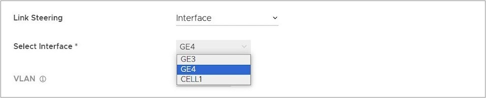
The link steering policy can be applied to the interface, for example, GE2 or GE3, which differs depending on the Edge model and the location. This is the least desirable option to use in the business policy because IT administrators must be fully aware of the Edge connectivity to specify the interface to use.
Link Steering and On-demand Remediation
There are four possible options for Link Steering – Auto, Preferred, Mandatory, and Available.
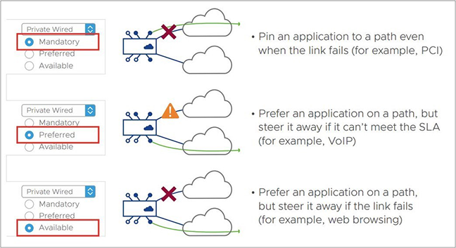
Link Selection Mandatory– Pin the traffic to the link or the transport group. The traffic never steers away regardless of the condition of the link including outage. On-demand remediation triggers to mitigate brownout condition such as packet loss and jitter.
For example, Netflix has a low priority for the application and requires staying on the public wired links at all times.
- When the preferred Internet link has multiple public WAN link alternatives. Application traffic stays on the preferred link as long as it meets SLA for that application, and steers to other public links once the preferred link cannot deliver the SLA needed by the application. When there is no link to steer to, meaning all public links fail to deliver the SLA needed by the application, and enables on-demand remediation. Alternatively, instead of steering the application away as soon as the current link cannot deliver the SLA needed by the application, DMPO can enable the on-demand remediation until the degradation becomes too severe to remediate. DMPO steers the application to the better link.
- Example - Prefer the video collaboration application on the Internet link until it fails to deliver the SLA needed by video, then steer to a public link that meets the application SLA.
- When the preferred Internet link has multiple public WAN and private WAN link alternatives, the application traffic stays on the preferred link as long as it meets SLA for that application, and steers to another public link once the preferred link cannot deliver the SLA needed by the application. The preferred link does not steer to a private link in the event of an SLA failure, and only steers to that private link in the event that both the preferred link and another public link become either unstable or down. When no link exists, meaning another public link failed to deliver the SLA needed by the application, Orchestrator enables on-demand remediation. Alternatively, instead of steering the application away as soon as the current link cannot deliver the SLA required by the application, DMPO can enable the on-demand remediation until the degradation becomes too severe to remediate. DMPO steers the application to a better link.
- Example A - Prefer the video collaboration application on the Internet link until it fails to deliver the SLA needed by video, then steer to a public link that meets this application SLA.
- Example B - Prefer the video collaboration application on the Internet link until it goes unstable or drops completely, other public links are also unstable or have also dropped completely, then steer to an available private link.
- When the preferred Internet link has only private WAN link alternatives, the application traffic stays on the preferred link regardless of the SLA status for that application, and does not steer to another private links even if the preferred link cannot deliver the SLA required by the application. In place of steering to the private links on an SLA failure for that application, Orchestrator enables on-demand remediation. The preferred link steers to the private link(s) and would only steer to another private link(s) in the event that the preferred link was either unstable or completely down.
- Example: Prefer the video collaboration application on the Internet link until the link goes unstable or drops completely, and then steer to an available private link.
The default behavior of treating a private link with reference to a preferred link (i.e., that a preferred linkonly redirects to a private link if the preferred link is unstable or offline) is configurable through a setting on the Orchestrator UI.
Link Selection Available– This option picks the available link as long as it is up. DMPO enables on-demand remediation if the link fails to meet the SLA. DMPO does not redirect the application flows to another link unless the link is down.
Example - Web traffic is backhauled over the Internet link to the hub site using the Internet link as long as it is active, regardless of SLA.
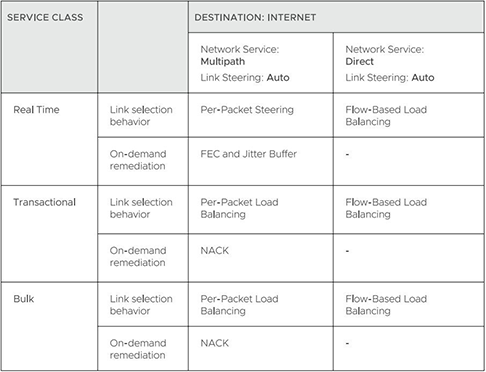
Link Selection Auto – By default, DMPO automatically picks the best links based on the type of application and enables on-demand remediation when needed. There are four possible combinations of Link steering and On-demand Remediation for Internet applications. Traffic within the enterprise (VPN) always goes through the DMPO tunnels, so it always receives the benefits of on-demand remediation.
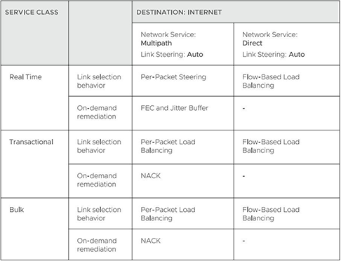
The below examples explain the default DMPO behavior for different type of applications and link conditions. Please see the appendix section for the default SLA for different application types.
- Scenario - One link meets the SLA for the application. DMPO picks the best available link.
- Scenario - One link has packet loss above the SLA for the application. DMPO enables FEC for the real-time applications on this link.
- Scenario - Two links with loss occurring on only one link. DMPO enables FEC on both links.
- Scenario - Multiple links with loss occurring on multiple links. DMPO enables FEC on the two best links.
- Scenario - Two links but one link lacks stability, and misses three consecutive heartbeats. DMPO marks the link as unusable and steers the flow to the next best available link.
- Scenario - Two links experiencing both jitter and loss. DMPO enables FEC and jitter buffer on both links. Jitter buffer is enabled when jitter is more than 7 ms for voice and more than 5 ms for video. The sending DMPO endpoint tells the receiving DMPO endpoint to enable jitter buffer. The receiving DMPO endpoint buffers up to 10 packets or 200 ms of traffic. It uses the original timestamp in the DMPO header to calculate the flow rate for de-jitter buffer. If the flow is not constant, it disables jitter buffering.
Example: Transactional and bulk applications. Enables NACK if packet loss exceeds the threshold that is acceptable per application type (see the appendix for this value).
Secure Traffic Transmission
DMPO encrypts both the payload and the tunnel header with IP sec transport mode end-to-end for private or internal traffic. The payload contains the user traffic. DMPO supports AES128 and AES256 for encryption. It uses the PKI and IKEv2 protocols for IP sec key management and authentication.
Protocols and Ports
- UDP/2426 – Use this port for overlay tunnel management and information exchange between the two DMPO endpoints, Edges and Gateways. Also use it for secure data traffic or unimportant data such as SFDC traffic from branch to the cloud between Edge and Gateway. SFDC traffic uses TLS encryption.
- UDP/500 and UDP/4500 – Use these ports are for IKEv2 negotiation and for IPsec NAT transparency.
- IP/50 – Use this protocol for IPsec over native IP protocol 50 (ESP) when no NAT exists between the two DMPO endpoints.
Appendix- QoE threshold and Application SLA
DMPO uses the SLA threshold below for different types of applications. It immediately takes action to redirect the affected application flows or perform on-demand remediation when the WAN link condition exceeds one or more thresholds. Packet loss is calculated by dividing the number of lost packets by the total packets in the last 1-minute interval. The DMPO endpoints communicate the number of lost packets every second. The QoE report also reflects this threshold.
DMPO also takes action immediately when it loses communications (no user data or probes) within 300 ms.
Beginning in Release 5.2.0, users have the capability to modify the threshold values for latency for video, voice, and transactional traffic types through a Customizable QoE feature. This means that customers can include high latency links as part of the selection process and the Orchestrator applies the new values to the QoE monitoring page.
Solution Components
This section describes Arista VeloCloud SD-WAN solution components.
VeloCloud Edge
A thin “Edge” with zero IT touch provisioned from the cloud for secured, optimized connectivity to applications and virtual services. Edges are zero-touch, enterprise-class devices or virtual software that provide secure and optimized connectivity to private, public, and hybrid applications and compute and virtual services. Edges perform deep application recognition, application and per-packet steering, on-demand remediation performance metrics, and end-to-end Quality of Service (QoS) in addition to hosting Virtual Network Function (VNF) services. An Edge pair deployment provides High Availability (HA). Users can deploy Edges in branches, large sites, and data centers. All other network infrastructure is available on demand in the cloud.
VeloCloud Orchestrator
Host the VeloCloud Orchestrator and provide centralized enterprise-wide configuration and real-time monitoring. It also orchestrates the data flow into and through the SD-WAN overlay network and provides one-click provisioning of virtual services across Edges.
VeloCloud Gateways
The VeloCloud SD-WAN network consists of Gateways, providing SD-WAN services to the doorstep of SaaS, IaaS, and cloud network services and access to private backbones. Arista VeloCloud SD-WAN deploys multi-tenant, virtual Gateways. The Gateways provide the advantage of an on-demand, scalable, and redundant cloud network for optimized paths to cloud destinations and zero-installation applications.
For additional information about the VeloCloud Gateways functionality and resiliency, see Arista.
SD-WAN Edge Performance and Scale Data
This section covers the VeloCloud SD-WAN edge's performance and scale architecture. It provides recommendations based on tests conducted on various Edge configurations with specific service combinations and explains performance and scale data points and how to use them.
Introduction
The tests represent common deployment scenarios to provide recommendations for most deployments. The test data herein does not provide either all-inclusive metrics or performance or scale limits. In certain implementations, the observed performance exceeds the test results, and in other specific services, extremely small packet sizes, or other factors can reduce performance below the test results.
Customers are welcome to perform independent tests, and results could vary. However, recommendations based on these test results are adequate for most deployments.
VeloCloud Edge
Arista VeloCloud SD-WAN Edges are zero-touch, enterprise-class appliances that provide secure, optimized connectivity for private, public, and hybrid applications and compute and virtual services. VeloCloud Edges perform deep application recognition of traffic flows, performance metrics measurements of underlay transport, and end-to-end service quality by applying packet-based link steering and on-demand application remediation, in addition to supporting other virtual network services.
Throughput Performance Test Topologies
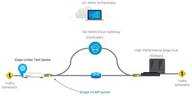
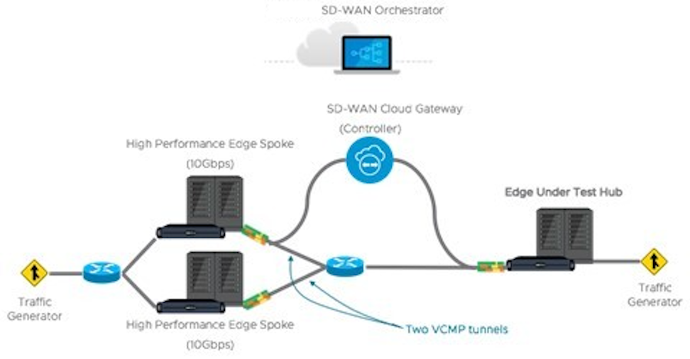
Test Methodology
This subsection details the performance and scale test methodology used to derive the results.
Performance Test Methodology
- A fully operational SD-WAN network overlay (DMPO tunnels) test topology measured performance in order to exercise the SD-WAN features and obtain results used to size WAN networks appropriately. Testing used stateful traffic that establishes multiple flows (connections) and a mix of well-known applications. The number of flows depended on the platform model tested. Platforms are divided by expected aggregate performance of under 1 Gbps and over 1 Gbps models. Typically, hundreds of flows are required to fully exercise and determine the max throughput of platforms expected to perform under 1 Gbps. And thousands of flows used to exercise platforms of over 1 Gbps. The traffic profiles simulate two network traffic conditions:
- Large Packet- a 1300-byte condition.
- IMIX- a mix of packet sizes that average to a 417-byte condition.
- Performance results recorded at a packet drop rate (PDR) of 0.01%. The PDR mark provides a more realistic performance result which accounts for normal packet drop that may occur within the SD-WAN packet pipeline in the device. A PDR of 0.01% does not impact application experience even in single link deployment scenarios.
- The device under test is configured with the following DMPO features: IPsec encrypted using AES-128 and SHA1 for hashing, Application Recognition, link SLA measurements, and per-packet forwarding. Business Policy is configured to match all traffic as bulk/low priority to prevent DMPO NACK or FEC from executing and incorrectly altering the traffic generator’s packet count tracking.
Test Results
VeloCloud Edge Performance and Scale Results
Performance metrics are based on the Test Methodology detailed earlier.
Switched Port Performance: Arista designed VeloCloud Edges to be deployed as gateway routers between the LAN and the WAN. However, the Edges also provide the flexibility of meeting a variety of other deployment topologies. For example, configure SD-WAN Edges with interfaces to operate as switched ports—allowing the switching of LAN traffic between various LAN interfaces without the need for an external device.
- The Edge device's Maximum Throughput is the sum of throughput across all interfaces of the Edge under test.
- Overall traffic is the “aggregate” of all traffic flows going to and from an Edge device.
| VeloCloud Edge | 510, 510N | 510-LTE | 520 | 520V | 540 | 610, 610C, 610N | 610-LTE | 710-W |
|---|---|---|---|---|---|---|---|---|
| Maximum Throughput Large Packet (1300-byte) | ||||||||
| Routed Mode All Ports | 850 Mbps | 850 Mbps | 850 Mbps | 850 Mbps | 1.5 Gbps | 850 Mbps | 850 Mbps | 950 Mbps |
| Maximum Throughput Internet Traffic (IMIX) | ||||||||
| Routed Mode All Ports | 300 Mbps | 300 Mbps | 300 Mbps | 300 Mbps | 650 Mbps | 300 Mbps | 300 Mbps | 350 Mbps |
| Routed Mode All Ports with IPS, Malicious IP Filtering, and Stateful Firewall activated. | 150 Mbps | 150 Mbps | 150 Mbps | 150 Mbps | 350 Mbps | 175 Mbps | 175 Mbps | 250 Mbps |
| Other Scale Vectors | ||||||||
| Maximum Tunnel Scale | 50 | 50 | 50 | 50 | 100 | 50 | 50 | 50 |
| Flows Per Second | 2,400 | 2,400 | 2,400 | 2,400 | 4,800 | 2,400 | 2,400 | 4,000 |
| Maximum Concurrent Flows | 225K | 225K | 225K | 225K | 225K | 225K | 225K | 225K |
| Maximum Concurrent Flows with IPS, Malicious IP Filtering, and Stateful Firewall activated. | 110K | 110K | 110K | 110K | 110K | 110K | 110K | 110K |
| Maximum Number of BGP Routes | 100K | 100K | 100K | 100K | 100K | 100K | 100K | 110K |
| Maximum Number of Segments | 32 | 32 | 32 | 32 | 32 | 32 | 32 | 32 |
| Maximum Number of NAT Entries | 225K | 225K | 225K | 225K | 225K | 225K | 225K | 225K |
| VeloCloud Edge | 620, 620C, 620N | 640, 640C, 640N | 680, 680C, 680N | 840 | 2000 | 3400, 3400C | 3800, 3800C | 3810 |
|---|---|---|---|---|---|---|---|---|
| Maximum Throughput Large Packet (1300-byte) | ||||||||
| Routed Mode All Ports | 1.55 Gbps | 5.5 Gbps | 8.5 Gbps | 6.5 Gbps | 15.5 Gbps | 11 Gbps | 16 Gbps | 16 Gbps |
| Maximum Throughput Internet Traffic (IMIX) | ||||||||
| Routed Mode All Ports | 950 Mbps | 2.2 Gbps | 3.2 Gbps | 2.2 Gbps | 6.2 Gbps | 3.6 Gbps | 6.5 Gbps | 6.5 Gbps |
| Routed Mode All Ports with IPS, Malicious IP Filtering, and Stateful Firewall activated. | 600 Mbps | 800 Mbps | 1.5 Gbps | 1.0 Gbps | 4.0 Gbps | 2.3 Gbps | 4.5 Gbps | 4.5 Gbps |
| Other Scale Vectors | ||||||||
| Maximum Tunnel Scale | 100 | 400 | 800 | 400 | 6,000 | 4,000 | 6,000 | 6,000 |
| Flows Per Second | 4,800 | 19,200 | 19,200 | 19,200 | 50,000 | 38,400 | 50,000 | 50,000 |
| Maximum Concurrent Flows | 460K | 1.15M | 1.9M | 1.9M | 1.9M | 1.9M | 3.8M | 3.8M |
| Maximum Concurrent Flows with IPS, Malicious IP Filtering, and Stateful Firewall activated. | 230K | 460K | 960K | 460K | 1.9M | 960K | 1.9M | 1.9M |
| Maximum Number of BGP Routes | 100K | 100K | 100K | 100K | 100K | 100K | 100K | 100K |
| Maximum Number of Segments | 128 | 128 | 128 | 128 | 128 | 128 | 128 | 128 |
| Maximum Number of NAT Entries | 460K | 960K | 960K | 960K | 1.9M | 960K | 1.9M | 1.9M |
| VeloCloud Edge | 720 | 740 | 4100 | 5100 |
|---|---|---|---|---|
| Max throughput per Edge with routed-mode ports (1300-byte) | 3 Gbps | 10 Gbps | 30 Gbps | 100 Gbps |
| Max throughput per Edge with routed-mode ports (IMIX)2 | 1.5 Gbps | 4.2 Gbps | 12 Gbps | 40 Gbps |
| Max tunnel scale | 400 | 800 | 12,000 | 20,000 |
| Flow per second | 18,000 | 26,000 | 50,000 | 180,000 |
| Max number of BGP routes | 100K | 100K | 100,000 | 100,000 |
| Max segments | 128 | 128 | 128 | 128 |
| Maximum NAT entries | 460K | 960K | 1.9M | 1.9M |
- Large Packet performance is based on a large packet (1300-byte) payload with AES-128 encryption and DPI turned on.
- Internet Traffic (IMIX) performance is based on an average packet size of 417-byte payload with AES-128 encryption and DPI turned on.
- IPS and Stateful Firewall performance numbers were measured using TREX setup with an average packet size of 400-bytes.
| Edge Model | 520V | 620, 620C, 620N | 640, 640C, 640N | 680, 680C, 680N | 840 | 3400, 3400C | 3800, 3800C | 3810 |
|---|---|---|---|---|---|---|---|---|
| Max. Throughput with FW VNF (1300-byte) | 100 Mbps | 300 Mbps | 600 Mbps | 1 Gbps | 1 Gbps | 2 Gbps | 3 Gbps | 3 Gbps |
| Edge Model | 510, 510N | 510-LTE | 520, 520v | 540 | 610, 610C, 610N | 610-LTE | 710-W |
|---|---|---|---|---|---|---|---|
| Maximum Throughput (IMIX) Across Enhanced HA Link | 220 Mbps | 220 Mbps | 220 Mbps | 480 Mbps | 220 Mbps | 220 Mbps | 260 Mbps |
| Edge Model | 620, 620C, 620N | 640, 640C, 640N | 680, 680C, 680N | 840 | 2000 | 3400, 3400C | 3800, 3800C | 3810 |
|---|---|---|---|---|---|---|---|---|
| Maximum Throughput (IMIX) Across Enhanced HA Link | 700 Mbps | 1 Gbps | 2 Gbps | 1 Gbps | 4 Gbps | 2.5 Gbps | 5 Gbps | 5 Gbps |
Platform Independent Edge Scale Numbers
The Edge Scale numbers listed in the following table provide platform independent information and valid for all Edge models, both hardware and virtual.
| Feature | Supported Number | |
|---|---|---|
| IPv4 | IPv6 | |
| Maximum number of Port Forwarding rules on a single segment | 128 | 128 |
| Maximum number of Port Forwarding rules across 16 segments | 128 | 128 |
| Maximum number of Port Forwarding rules across 128 segments | 128 | 128 |
| Maximum number of Outbound Firewall Rules on a single segment | 2040 | 2040 |
| Maximum number of Outbound Firewall Rules across 16 segments | 2040 | 2040 |
| Maximum number of Outbound Firewall Rules across 128 segments | 2040 | 2040 |
| Maximum number of 1:1 NAT rules on a single segment | 128 | 128 |
| Maximum number of 1:1 NAT rules across 16 segments | 128 | 128 |
| Maximum number of 1:1 NAT rules across 128 segments | 128 | 128 |
| Maximum number of LAN side NAT rules on a single segment | 256 | - |
| Maximum number of LAN side NAT rules across 16 segments | 256 | - |
| Maximum number of LAN side NAT rules across 128 segments | 256 | - |
| Maximum number of Object Groups (1000 business policies, each business policy assigned to one object group, each object group supports 255 address groups) | 1000 | 1000 |
Virtual Edge
| Edge Device | Maximum Throughput | Maximum Number of Tunnels | Flows Per Second | Maximum Concurrent Flows | Maximum Number of Routes | Maximum Number of Segments | |
|---|---|---|---|---|---|---|---|
| ESXi Virtual Edge (2-core, VMXNET3) | 1.5 Gbps (1300-byte) 900 Mbps (IMIX) | 50 | 2400 | 240K | 35K | 128 | |
| KVM Virtual Edge (2-core, Linux Bridge) | 800 Mbps (1300-byte) 250 Mbps (IMIX) | 50 | 2400 | 240K | 35K | 128 | |
| KVM Virtual Edge (2-core, SR-IOV) | 1.5 Gbps (1300-byte) 900 Mbps (IMIX) | 50 | 2400 | 240K | 35K | 128 | |
| ESXi Virtual Edge (4-core, VMXNET3) | 4 Gbps (1300-byte) 1.5 Gbps (IMIX) | 400 | 4800 | 480K | 35K | 128 | |
| ESXi Virtual Edge (4-core, SR-IOV) | 5 Gbps (1300-byte) 1.5 Gbps (IMIX) | 400 | 4800 | 480K | 35K | 128 | |
| KVM Virtual Edge (4-core, Linux Bridge) | 1 Gbps (1300-byte) 350 Mbps (IMIX) | 400 | 4800 | 480K | 35K | 128 | |
| KVM Virtual Edge (4-core, SR-IOV) | 4 Gbps (1300-byte) 1.5 Gbps (IMIX) | 400 | 4800 | 480K | 35K | 128 | |
| ESXi Virtual Edge (8-core, VMXNET3) | 6 Gbps (1300-byte) 2 Gbps (IMIX) | 800 | 28800 | 1.9M | 35K | 128 | |
| ESXi Virtual Edge (8-core, SR-IOV) | 6 Gbps (1300-byte) 3 Gbps (IMIX) | 800 | 28800 | 1.9M | 35K | 128 | |
| KVM Virtual Edge (8-core, SR-IOV | 6.5 Gbps (1300-byte) 3.2 Gbps (IMIX) | 800 | 28800 | 1.9M | 35K | 128 | |
| 2 vCPU | 4vCPU | 8vCPU | 10vCPU | |
|---|---|---|---|---|
| Minimum Memory (DRAM) | 8 GB | 16 GB | 32 GB | 32 GB |
| Minimum Storage | 8 GB | 8 GB | 16 GB | 16 GB |
| Supported Hypervisors | Software version 4.0 and above:
|
|||
| Supported Public Cloud | AWS, Azure, GCP, and Alibaba | |||
| Support Network I/O | SR-IOV, VirtIO, VMXNET3 | |||
| Recommended Host Settings | CPUs at 2.0 GHz or higher CPU configuration:
|
|||
Public Cloud
| AWS Instance Type | c5.large | c5.xlarge | c5.2xlarge | c5.4xlarge |
|---|---|---|---|---|
| Maximum Throughput | 100 Mbps (1300-byte) 50 Mbps (IMIX) | 200 Mbps (1300-byte) 100 Mbps (IMIX) | 1.5 Gbps (1300-byte) 450 Mbps (IMIX) | 6 Gbps (1300-byte) 2 Gbps (IMIX)* |
| Maximum Tunnels | 50 | 400 | 800 | 2,000 |
| Flows Per Second | 1,200 | 2,400 | 4,800 | 9,600 |
| Maximum Concurrent Flows | 125,000 | 250,000 | 550,000 | 1.9M |
| Maximum Number of Routes | 35,000 | 35,000 | 35,000 | 35,000 |
| Maximum Number of Segments | 128 | 128 | 128 | 128 |
| Routed Mode All Ports with IPS, Malicious IP Filtering, and Stateful Firewall activated. | - | - | - | 4.6 Gbps (1300-byte) 1.2 Gbps (IMIX)* |
*Values captured with ENAv2.
| Azure VM Series | D2d v4 | D4d v4 | D8d v4 | D16d v4 |
|---|---|---|---|---|
| Maximum Throughput | 100 Mbps (1300-byte) 50 Mbps (IMIX) | 200 Mbps (1300-byte) 100 Mbps (IMIX) | 1 Gbps (1300-byte) 450 Mbps (IMIX) | 1 Gbps (1300-byte) 450 Mbps (IMIX) |
| Maximum Tunnels | 50 | 400 | 800 | 2000 |
| Flows Per Second | 1,200 | 2,400 | 4,800 | 4,800 |
| Maximum Concurrent Flows | 125,000 | 250,000 | 550,000 | 550,000 |
| Maximum Number of Routes | 35,000 | 35,000 | 35,000 | 35,000 |
| Maximum Number of Segments | 128 | 128 | 128 | 128 |
| Azure VM Series | Ds3 v2 | Ds4 v2 | Ds5 v2 | D4d v5 | D8d v5 | D16d v5 |
|---|---|---|---|---|---|---|
| Maximum Throughput | 2.5 Gbps (1300-byte) 1.5 Gbps (IMIX) | 5.3 Gbps (1300-byte) 2.7 Gbps (IMIX) | 6.5 Gbps (1300-byte) 3.1 Gbps (IMIX) | 4.5 Gbps (1300-byte) 1.3 Gbps (IMIX) | 6.3 Gbps (1300-byte) 2.7 Gbps (IMIX) | 6.4 Gbps (1300-byte) 2.9 Gbps (IMIX) |
| Maximum Tunnels | 400 | 800 | 2000 | 400 | 800 | 2000 |
| Flows Per Second | 2,400 | 4,800 | 4,800 | 2,400 | 4,800 | 4,800 |
| Maximum Concurrent Flows | 250,000 | 550,000 | 550,000 | 250,000 | 550,000 | 550,000 |
| Maximum Number of Routes | 35,000 | 35,000 | 35,000 | 35,000 | 35,000 | 35,000 |
| Maximum Number of Segments | 128 | 128 | 128 | 128 | 128 | 128 |
- Azure Accelerated Networking is supported only from release 5.4.0.
- Accelerated Networking is supported only on ConnectX-4 and ConnectX-5 NICs.
| GCP Instance Type | n2-highcpu-4 | n2-highcpu-8 | n2-highcpu-16 |
|---|---|---|---|
| Maximum Throughput | 850 Mbps (1300-byte) 500 Mbps (IMIX) | 4.5 Gbps (1300-byte) 1.6 Gbps (IMIX) | 6.5 Gbps (1300-byte) 1.9 Gbps (IMIX) |
| Maximum Tunnels | 50 | 400 | 800 |
| Flows Per Second | 1,200 | 2,400 | 4,800 |
| Maximum Concurrent Flows | 125,000 | 250,000 | 550,000 |
| Maximum Number of Routes | 35,000 | 35,000 | 35,000 |
| Maximum Number of Segments | 128 | 128 | 128 |
Use of DPDK on VeloCloud Edges
To improve packet throughput performance, VeloCloud Edges utilizes Data Plane Development Kit (DPDK) technology. DPDK uses a set of data plane libraries and drivers provided by Intel for offloading TCP packet processing from the operating system kernel to processes running in user space and resulting in higher packet throughput. For additional details, see https://www.dpdk.org/.
Edge hardware models 620 and higher, and all virtual Edges, use DPDK by default on the routed interfaces. Edges do not use DPDK on the switched interfaces. A user cannot activate or deactivate DPDK for an Edge interface.
Capabilities
This section discusses VeloCloud SD-WAN capabilities.
Dynamic Multi-path Optimization
VeloCloud SD-WAN Dynamic Multi-path Optimization comprises automatic link monitoring, dynamic link steering, and on-demand remediation.
Link Steering and Remediation
Dynamic, application-aware per-packet link steering performs automatically based on the business priority of the application, embedded knowledge of the its network requirements, and the real-time capacity and performance of each link. On-demand mitigation of individual link degradation through forward error correction, jitter buffering, and negative acknowledgment proxy also protects the performance of priority and network-sensitive applications. The dynamic per-packet link steering and on-demand mitigation combine to deliver robust, sub-second blocking, and limited protection improving application availability, performance, and end-user experience.
Cloud VPN
Cloud VPN is a one-click, site-to-site, VPNC-compliant, IPsec VPN that connects VeloCloud SD-WAN and non-SD-WAN destinations delivering real-time status and the health of the sites. The Cloud VPN establishes dynamic edge-to-edge communication for all branches based on service-level objectives and application performance. Cloud VPN also delivers secure connectivity across all branches with PKI scalable key management. New branches join the VPN network automatically with access to all resources in other branches, enterprise data centers, and 3rd party data centers, like Amazon AWS.
Firewall
VeloCloud SD-WAN delivers a stateful and context-aware (application, user, device) integrated application-aware firewall with granular control of sub-applications, supporting protocol-hopping applications, such as Skype and other peer-to-peer applications. For example, turn off Skype video and chat, but leave Skype audio enabled. The secure firewall service is user- and device OS-aware and can separate voice, video, data, and compliance traffic. On the corporate network, users can easily control the policies for BYOD devices such as Apple iOS, Android, Windows, and Mac OS.
Network Service Insertion
The VeloCloud SD-WAN Solution supports a platform to host multiple virtual network functions to eliminate single-function appliances and reduce branch IT complexity. VeloCloud SD-WAN service-chains traffic from the branch to cloud-based and enterprise regional hub services, with assured performance, security, and manageability. Branches leverage consolidated security and network services, including those from partners like Zscaler and Websense. Users can insert services in the cloud and on-premise with application-specific policies using a simple click-to-enable interface.
Activation
Edge appliances automatically authenticate, connect, and receive configuration instructions after theyconnect to the Internet in a zero-touch deployment. They deliver a highly available deployment with Edge redundancy protocol and integrate with the existing network with support for Open Shortest Path First (OSPF) and Border Gateway Protocol (BGP) routing protocols, leveraging benefits from dynamic learning and automation.
Overlay Flow Control
The Edge learns routes from adjacent routers through OSPF and BGP. It sends the learned routes to the Gateway/Controller. The Gateway/Controller acts like a route reflector and sends the learned routes to other Edge. The Overlay Flow Control (OFC) facilitates enterprise-wide route visibility and control allowing for easy programming for full and partial overlay.
OSPF
VeloCloud SD-WAN supports inbound/outbound filters to OSPF neighbors, OE1/OE2 route types, and MD5 authentication. Routes learned through OSPF automatically redistribute to the Controller hosted in the cloud or on-premises.
BGP
VeloCloud SD-WAN supports inbound and outbound filters set to Deny or optionally add or change the BGP attribute to influence path selection including RFC 1998 community, MED, AS-Path prepends, and local preference.
Segmentation
Network segmentation is an important feature for both enterprises and service providers. In the most basic form, segmentation provides network isolation for management and security reasons. The most common forms of segmentation are VLANs for L2 and VRFs for L3.
Typical Use Cases for Segmentation:
- Line of Business Separation - Engineering, HR, etc., for Security/Audit.
- User Data Separation - Guest, PCI, and Corporate traffic separation.
- Enterprise uses overlapping IP addresses in different VRFs.
However, the previous approach is limited to a single box or two physically connected devices. To extend the functionality, segmentation information must be carried across the network.
VeloCloud SD-WAN offers end-to-end segmentation. When the packet traverses through the Edge, Orchestrator adds the Segment ID to the packet and forwards it to the Hub and cloud Gateway, allowing network service isolation from the Edge to the cloud and data center. This allows prefixes to be grouped into a unique routing table, making the business policy segment aware.
Routing
In Dynamic Routing, Edge learns routes from adjacent routers through OSPF or BGP. The Orchestrator maintains all the dynamically learned routes in a global routing table called the Overlay Flow Control (OFC). The Overlay Flow Control allows management of dynamic routes in the case of "Overlay Flow Control sync" and "change in Inbound/Outbound filtering configuration." The change in inbound filtering for a prefix from IGNORE to LEARN would fetch the prefix from the Overlay Flow Control and install it into the Unified routing table.
For additional information, see Configure Dynamic Routing with OSPF or BGP.
Business Policy Framework
Quality of Service (QoS), resource allocations, link/path steering, and error correction automatically apply based on business policies and application priorities. Orchestrate traffic based on transport groups defined by private and public links, policy definition, and link characteristics.
Network Topologies
This section describes network topologies for branches and data centers.
Branches to Private Third Party (VPN)
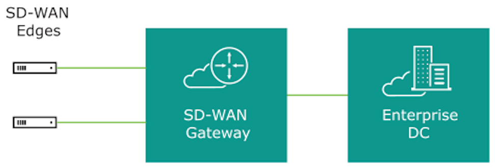
Data Center Network Topology
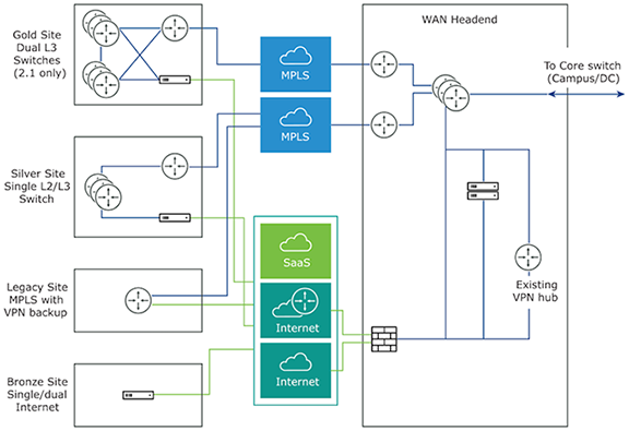
The Data Center Network topology consists of two hubs and multiple branches, with or without an Edge. Each hub has hybrid WAN connectivity with several branch types. The MPLS network runs BGP and peers with all the CE routers. At Hub 1, Hub 2, and Silver 1 sites, the L3 switch runs OSPF, or BGP with the CE router and firewall in case of hub sites.
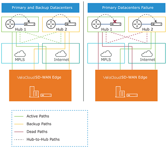
In some cases, there may be redundant data centers which advertise the same subnets with different costs. In this scenario, both data centers can be configured as Edge-to-Edge VPN hubs. Since all edges connect directly to each hub, the hubs in fact also connect directly to each other. Based on route cost, traffic redirects to the preferred active data center.
In previous versions, users could create an enterprise object using Zscaler or Palo Alto Networks as a generic Non SD-WAN Destination. In 4.0 version, that object now becomes a Non SD-WAN Destination.
The Cloud-Delivered solution of Arista combines the economics and flexibility of the hybrid WAN with the deployment speed and low maintenance of cloud-based services. It dramatically simplifies the WAN by delivering virtual services from the cloud to branch offices. Arista customer-premise equipment, the Edge, aggregates multiple broadband links such as Cable, DSL, 4G-LTE, at the branch office and sends the traffic to Gateways. Using cloud-based orchestration, the service can connect the branch office to anydata center, including enterprise, cloud, or Software-as-a-Service (SaaS) data centers.
Edge consists of a compact, thin Edge device with zero-IT-touch provisioning from the cloud for secure, optimized connectivity to applications and data. A cluster of gateways deploys globally at top-tier cloud data centers to provide scalable and on-demand cloud network services. Working with the Edge, the cluster delivers Dynamic Multi-path Optimization so multiple, ordinary broadband links appear as a single, high-bandwidth link. Orchestrator management provides centralized configuration, real-time monitoring, and one-click provisioning of virtual services.
Tunnel Overhead and MTU
VeloCloud, like any overlay, imposes additional overhead on traffic that traverses the network. This section first describes the overhead added in a traditional IPsec network and how it compares with VeloCloud, followed by an explanation of how this added overhead relates to MTU and packet fragmentation behaviors in the network.
IPsec Tunnel Overhead
- Padding
- AES encrypts data in 16-byte blocks, called block size.
- If the body of a packet is smaller than or indivisible by the block size, it is padded to match the block size.
- Examples:
- A 1-byte packet becomes 16 bytes with 15 bytes of padding.
- A 1400-byte packet becomes 1408 bytes with 8 bytes of padding.
- A 64-byte packet does not require any padding.
- IPsec headers and trailers:
- UDP header for NAT Traversal (NAT-T).
- IP header for IPsec tunnel mode.
- ESP header and trailer.
| Element | Size in Bytes |
|---|---|
| IP Header | 20 |
| UDP Header | 8 |
| IPsec Sequence Number | 4 |
| IPsec SPI | 4 |
| Initialization Vector | 16 |
| Padding | 0 – 15 |
| Padding Length | 1 |
| Next Header | 1 |
| Authentication Data | 12 |
| Total | 66-81 |
VeloCloud Tunnel Overhead
To support Dynamic Multipath Optimization™ (DMPO), VeloCloud encapsulates packets in a protocol called the VeloCloud Multipath Protocol (VCMP). VCMP adds 31 bytes of overhead for user packets to support resequencing, error correction, network analysis, and network segmentation within a single tunnel. VCMP operates on an IANA-registered port of UDP 2426. To ensure consistent behavior in all potential scenarios such as unencrypted, encrypted and behind a NAT, ad encrypted but not behind a NAT, VeloCloud encrypts VCMP using transport mode IPsec and forces NAT-T to be true with a special NAT-T port of 2426.
Packets sent to the Internet through the SD-WAN Gateway do not encrypt by default, since they egress to the open Internet upon exiting the Gateway. As a result, Internet Multipath traffic has less overhead than that of VPN traffic.
| Element | Size in Bytes |
|---|---|
| IP Header | 20 |
| UDP Header | 8 |
| IPsec Sequence Number | 4 |
| IPsec SPI | 4 |
| VCMP Header | 23 |
| VCMP Data Header | 8 |
| Initialization Vector | 16 |
| Padding | 0 – 15 |
| Padding Length | 1 |
| Next Header | 1 |
| Authentication Data | 12 |
| Total | 97 – 112 |
| Element | Size in Bytes |
|---|---|
| IP Header | 20 |
| UDP Header | 8 |
| VCMP Header | 23 |
| VCMP Data Header | 8 |
| Total | 59 |
Impact of IPv6 Tunnel on MTU
VeloCloud SD-WAN supports IPv6 addresses to configure the Edge Interfaces and Edge WAN Overlay settings.
Users can set up the VCMP tunnel in the following environments: IPv4 only, IPv6 only, and dual stack. For more information, see IPv6 Settings.
When a branch has at least one IPv6 tunnel, DMPO uses this tunnel seamlessly along with other IPv4 tunnels. The packets for any specific flow can take any tunnel, IPv4 or IPv6, based on the real-time health of the tunnel. An example of specific flow is the path selection score for load-balanced traffic. In such cases, the increased size of the IPv6 header (additional 20 bytes) should be taken into account, and as a result, the effective path MTU will be reduced by 20 bytes. In addition, this reduced effective MTU will be propagated to the other remote branches through the Gateway so that the incoming routes into this local branch from other remote branches reflect the reduced MTU.
Path MTU Discovery
- For public Internet WAN links:
- Path MTU discovery performed to all Gateways.
- The MTU for all tunnels set to the minimum MTU discovered.
- For private WAN links:
- Path MTU discovery performed to all other Edges in the customer network.
- The MTU for each tunnel set based on the results of Path MTU discovery.
The Edge first attempts Path MTU discovery (RFC 1191),and sends a packet from the current known link MTU (Default 1500 bytes) to the peer with the Don’t Fragment (DF) bit set in the IP header. If the remote Edge or Gateway receives the packet, an acknowledgment packet of the same size returns to the Edge. If the packet cannot reach the remote Edge or Gateway due to MTU constraints, the intermediate device expects to send an ICMP destination unreachable (fragmentation needed) message. When the Edge receives the ICMP unreachable message, it validates the message and ensures the MTU value reported is sane). After the validation, adjust the MTU. The process then repeats until discovering the MTU.
In some cases (for example, USB LTE dongles), the intermediate device does not send an ICMP unreachable message even if the packet is too large. If RFC 1191 fails, the Edge did not receive an acknowledgment or ICMP unreachable, it falls back to RFC 4821 Packetization Layer Path MTU Discovery. The Edge attempts to perform a binary search to discover the MTU.
VPN Traffic and MTU
Now that the SD-WAN Edge has discovered the MTU and calculated the overheads, an effective MTU can be computed for client traffic. The Edge attempts to enforce this MTU as efficiently as possible for the various potential types of traffic received.
TCP Traffic
The Edge automatically performs TCP MSS (Maximum Segment Size) adjustment for TCP packets received. As SYN and SYN|ACK packets traverse the Edge, the MSS rewrites based on the Effective Packet MTU.
Non-TCP Traffic without DF Bit Set
If the packet is larger than the Effective Packet MTU, the Edge automatically performs IP fragmentation as per RFC 791.
Non-TCP Traffic with DF Bit Set
- The first time a packet is received for this flow (IP 5-tuple), the Edge drops the packet and sends an ICMP Destination unreachable (fragmentation needed) as per RFC 791.
- If subsequent packets received for the same flow which are still too large, these packets fragment into multiple VCMP packets and reassembled transparently before hand-off at the remote end.
Jumbo Frame Limitation
VeloCloud SD-WAN does not support jumbo frames as of Release 5.0. The maximum supported IP MTU, 1500,for packets sent across the overlay without fragmentation.
Branch Site Topologies
The Arista VeloCloud service defines two or more different branch topologies designated as Bronze, Silver, and Gold. In addition, configure pairs of EdgesHigh Availability (HA) at a branch location.
Bronze Site Topology
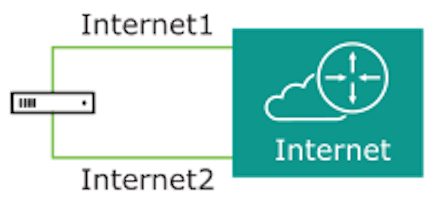
Silver Site Topology
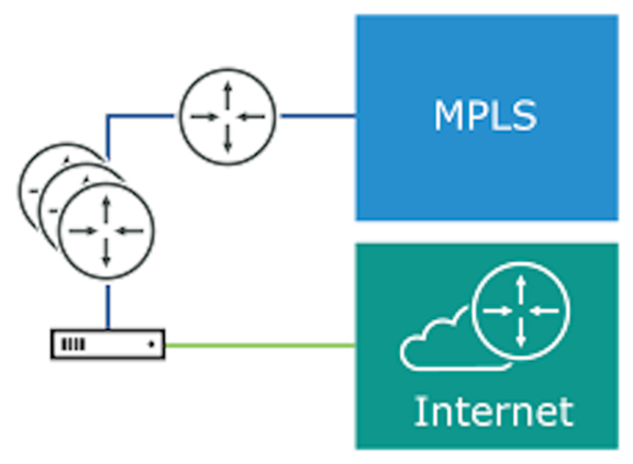
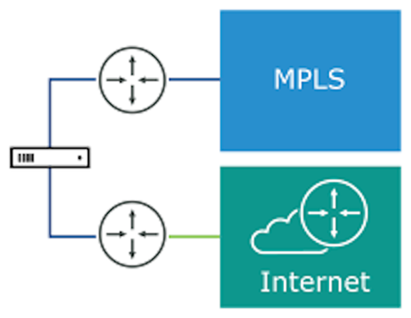
Gold Site Topology
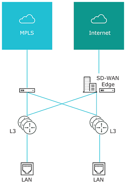
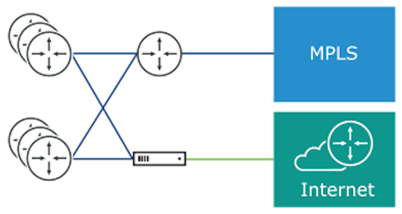
High Availability (HA) Configuration
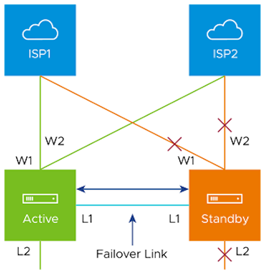
Connected the L1 ports on each edge establish a failover link. The standby Edge blocks all ports except the L1 port for the failover link.
On-Premise Topology
The on-premise topology consists of two hubs and multiple branches, with or without an Edge. Each hub has hybrid WAN connectivity and branch types.
In previous versions, users could create an enterprise object using Zscaler or Palo Alto Network as a generic Non SD-WAN Destination. In 4.0 version, that object becomes as a Non SD-WAN Destination.
The Cloud-Delivered solution of Arista VeloCloud combines the economics and flexibility of the hybrid WAN with the deployment speed and low maintenance of cloud-based services. It simplifies the WAN by delivering virtual services from the cloud to branch offices. The Arista VeloCloud customer-premise equipment, Edge, aggregates multiple broadband links, for example, Cable, DSL, and 4G-LTE at the branch office, and sends the traffic to Gateways. Using cloud-based orchestration, the service can connect the branch office to any of type of data center: enterprise, cloud, or Software-as-a-Service (SaaS).
The Edge consists of a compact, thin Edge device zero-IT-touch provisioned from the cloud for secure, optimized connectivity to applications and data. Orchestrator management provides centralized configuration and real-time monitoring.
Roles and Privilege Levels
- IT Administrator (or Administrator)
- Site Contact at each site where an Edge device is deployed.
Administrator
| Administrator Role | Description |
|---|---|
| Enterprise Standard Administrator | Can perform all configuration and monitoring tasks. |
| Enterprise Superuser | Can perform the same tasks as an Enterprise Standard Admin and can also create additional users with the Enterprise Standard Admin, Enterprise MSP, and Customer Support role. |
| Enterprise Support | Can perform configuration review and monitoring tasks but cannot view user identifiable application statistics and can only view configuration information. |
Site Contact
The Site Contact has the responsibility for Edge physical installation and activation with the Arista VeloCloud SD-WAN service. The Site Contact can be a non-IT person who can receive an email and perform the instructions in the email for Edge activation.
User Role Matrix
This section describes feature access according to Arista VeloCloud SD-WAN user roles.
Enterprise-level Orchestrator Features User Role Matrix
- R: Read
- W: Write (Modify/Edit)
- D: Delete
- NA: No Access
| Orchestrator Feature | Enterprise: Super User | Enterprise: Standard Admin | Customer Support | Read Only |
|---|---|---|---|---|
| R | R | R | R | |
| R | R | R | R | |
| R | R | R | NA | |
| R | R | R | NA | |
| R | R | R | NA | |
| RWD | RWD | R | R | |
| RWD | RWD | R | NA | |
| RWD | RWD | R | NA | |
| RWD | RWD | R | NA | |
| RWD | RWD | R | NA | |
| RWD | RWD | R | NA | |
| RWD | RWD | R | NA | |
| RW | RW | R | NA | |
| RW | RW | RW | NA | |
| RW | RW | RW | NA | |
| RW | RW | RW | NA | |
| RWD | RWD | RWD | NA | |
| RW | RW | RW | NA | |
| RW | R | R | NA |
Key Concepts
This section discusses the key concepts and the core configurations of Orchestrator.
Configurations
| Configuration | Description |
|---|---|
| Network | Defines basic network configurations, such as IP addressing and VLANs. Networks can be designated as Corporate or Guest and there can be multiple definitions for each network. |
| Network Services | Define several common services used by the VeloCloud Service, such as Backhaul Sites, Cloud VPN Hubs, Non SD-WAN Destinations, Cloud Proxy Services, DNS services, and Authentication Services. |
| Profile | Defines a template configuration to apply to multiple Edges. Configure a Profile by selecting a Network and Network Services. Apply a profile to one or more Edge models and defines the settings for the LAN, Internet, Wireless LAN, and WAN Edge Interfaces. Profiles can also provide settings for Wi-Fi Radio, SNMP, Netflow, Business Policies and Firewall configuration. |
| Edge | Configurations provide a complete group of settings that can be downloaded to an Edge device. The Edge configuration has a composite of settings from a selected Profile, a selected Network, and Network Services. An Edge configuration can also override settings or add ordered policies to those defined in the Profile, Network, and Network Services. |
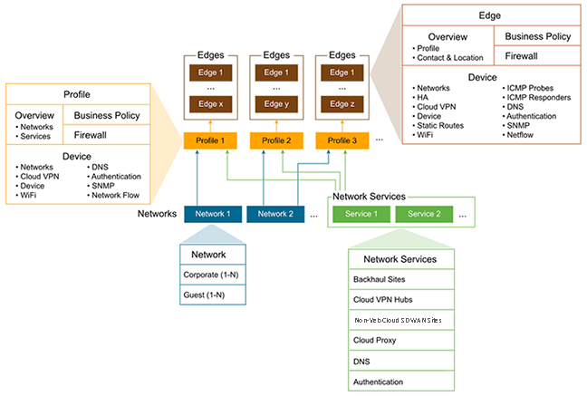
Networks
- Corporate or trusted networks configured with either overlapping addresses or non-overlapping addresses.
- Guest or untrusted networks which always use overlapping addresses.
With overlapping addresses, all Edges that use the Network have the same address space. Associate overlapping addresses with non-VPN configurations.
With non-overlapping addresses, an address space divides into blocks of an equal number of addresses. Non-overlapping addresses associate with VPN configurations. Assign address blocks to Edges that use the Network so that each Edge has a unique set of addresses. Non-overlapping addresses are required for Edge-to-Edge and Edge-to-Non SD-WAN Destination VPN communication. The configuration creates the required information to access an Enterprise Data Center Gateway for VPN access. An administrator for the Enterprise Data Center Gateway uses the IPsec configuration information generated during Non SD-WAN Destination VPN configuration to configure the VPN tunnel to the Non SD-WAN Destination.
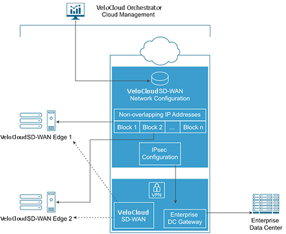
Network Services
Users can define Enterprise Network Services and use them across all the Profiles. This includes services for Authentication, Cloud Proxy, Non SD-WAN Destinations, and DNS. The defined Network Services are used only when they are assigned to a Profile.
Profiles
A profile consists of a named configuration that defines a list of VLANs, Cloud VPN settings, wired and wireless Interface Settings, and Network Services such as DNS Settings, Authentication Settings, Cloud Proxy Settings, and VPN connections to Non SD-WAN Destinations. Users can define a standard configuration for one or more Edges using the profiles.Profiles provide Cloud VPN settings for Edges configured for VPN. The Cloud VPN Settings can activate or deactivate Edge-to-Edge and Edge-to- Non SD-WAN Destination VPN connections.
Profiles can also define rules and configuration for the Business Policies and Firewall settings.
Edges
Assign a profile to an Edge and the Edge derives most of the configuration from the Profile.Users can use most of the settings defined in a Profile, Network, or Network Services without modification in an Edge configuration. However, users can override the settings for the Edge configuration elements to tailor an Edge for a specific scenario. This includes settings for Interfaces, Wi-Fi Radio Settings, DNS, Authentication, Business Policy, and Firewall.
In addition, configure an Edge to augment settings not present in Profile or Network configuration. This includes Subnet Addressing, Static Route settings, and Inbound Firewall Rules for Port Forwarding and 1:1 NAT.
Orchestrator Configuration Workflow
VeloCloud supports multiple configuration scenarios. The following table lists some of the common scenarios:| Scenario | Description |
|---|---|
| SaaS | Used for Edges that do not require VPN connections between Edges, to a Non SD-WAN Destination, or to a VeloCloud Site. The workflow assumes the addressing for the Corporate Network uses overlapping addresses. |
| Non SD-WAN Destination via VPN | Used for Edges that require VPN connections to a Non SD-WAN Destination such as Amazon Web Services, Zscaler, Cisco ISR, or ASR 1000 Series. The workflow assumes the addressing for the Corporate Network using non-overlapping addresses and the Non SD-WAN Destinations are defined in the profile. |
| VeloCloud Site VPN | Used for Edges that require VPN connections to a VeloCloud Site such as an Edge Hub or a Cloud VPN Hub. The workflow assumes the addressing for the Corporate Network using non-overlapping addresses and the VeloCloud Sites defined in the profile. |
- Network
- Network Services
- Profile
- Edge
| Quick Start Configuration Steps | SaaS | Non SD-WAN Destination VPN | VeloCloud Site VPN |
|---|---|---|---|
| Step 1: Network | Select Quick Start Internet Network | Select Quick Start VPN Network | Select Quick Start VPN Network |
| Step 2: Network Service | Use pre-configured Network Services | Use pre-configured Network Services | Use pre-configured Network Services |
| Step 3: Profile | Select Quick Start Internet Profile | Select Quick Start VPN Profile
Activate Cloud VPN and configure Non SD-WAN Destinations |
Select Quick Start VPN Profile
Activate Cloud VPN and configure VeloCloud Sites |
| Step 4: Edge | Add New Edge and activate the Edge | Add New Edge and activate the Edge | Add New Edge and activate the Edge |
Supported Browsers
| Browsers Qualified | Browser Version |
|---|---|
| Google Chrome | 77 – 143.0.7499.111 |
| Mozilla Firefox | 69.0.2 - 146.0.2 |
| Microsoft Edge | 42.17134.1.0 - 44.18362.449.0 |
| Apple Safari | 12.1.2 - 26.2 (21623.1.14.11.9) |
Supported USB Modems
This section lists the Supported USB Modems on Edge devices.
| CARRIER/MANUFACTURER | MODEL |
|---|---|
| Any/Inseego | Skyus 160 LTE Gateway |
| Any/Inseego | Skyus DS2 |
| AT&T/Inseego | Global Modem USB800 |
| Any/Inseego | Inseego USB 8 |
Important Notes
- Any customer procuring a USB modem for a Arista VeloCloud SD-WAN must select one from the above list to ensure support on their Edge.
- The four USB modems listed as supported provide worldwide coverage for all VeloCloud SD-WAN Customers.
- While all of the above may not be available in a specific market, at least one of the four should be procurable.
- For customers deploying a modem not listed above but which was previously listed as supported (referred to as "legacy" modems):
- Note that the existing legacy modems continue to work on Edges, but rather that VeloCloud SD-WAN Engineering no longer tests those modems against the latest Edge software and should not be expected to provide fixes for issues arising from these legacy modems.
- Any future modem purchases must be made from the above list.