Rear Panel
This section displays the rear panel of all switches covered by this guide. Depending on the modules installed, the rear panel on your switch may appear slightly different.
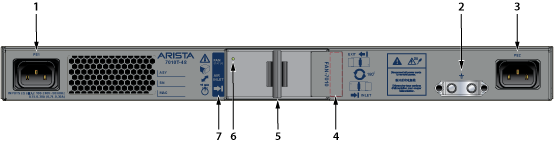
| 1 | Power Supply Module 1 | 4 | Airflow direction indicator label (inactive) | 7 | Airflow direction indicator label (active) |
| 2 | Grounding location | 5 | Fan release handle | ||
| 3 | Power Supply Module 2 | 6 | Fan status LED |
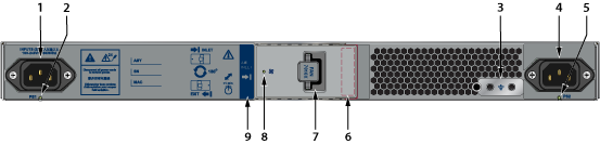
| 1 | Power supply module 1 | 4 | Power supply module 2 | 7 | Fan release handle |
| 2 | Power supply 1 status LED | 5 | Power supply 2 status LED | 8 | Fan status LED |
| 3 | Grounding location | 6 | Airflow direction indicator label (inactive) | 9 | Airflow direction indicator label (active) |
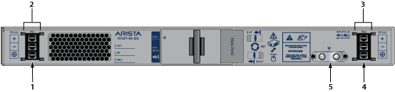
| 1 | Power supply 1 terminals | 3 | Power supply 2 terminal cover | 5 | Grounding location |
| 2 | Power supply 1 terminal cover | 4 | Power supply 2 terminals |
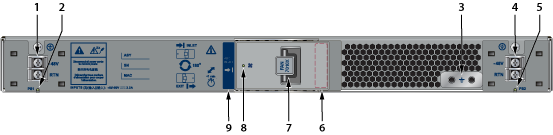
| 1 | Power supply 1 terminals | 4 | Power supply 2 terminals | 7 | Fan release handle |
| 2 | Power supply 1 status LED | 5 | Power supply 2 status LED | 8 | Fan status LED |
| 3 | Grounding location | 6 | Airflow direction indicator label (inactive) | 9 | Airflow direction indicator label (active) |