Rack Mounting the Switch
The rack mounting procedure is identical for all switches covered by this guide. Illustrations in this chapter depict the mounting of a DCS-7020SR-32C2 switch.
Les procédure de montage du bâti est identique pour tous les commutateurs visés par ce guide. Illustrations dans ce chapitre montrent le montage d’un interrupteur de DCS-7020SR-32C2.
- Two-Post Rack Mount provides instructions for mounting all switches in a two-post rack.
- Four-Post Rack Mount provides instructions for mounting all switches in a four-post rack.
After completing the instructions for your rack type, proceed to Cabling the Switch.
Two-Post Rack Mount
To mount the switch onto a two-post rack, attach the mounting ears to the chassis, then attach the ears to the rack posts. Two-post accessory kit includes 2x mounting ears as two-post mounting parts.
Attachment pins must engage all three upper bracket holes.
Goupilles de fixation doivent être bloquer tous les trois trous de la bride supérieure.
Attaching Mounting Brackets to the Chassis
- Use the screws to attach the brackets to the chassis.
Figure 1. Attaching Mounting Brackets to the Switch Chassis
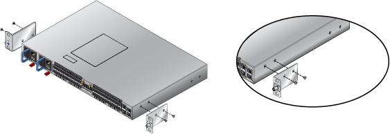 Note: DCS-7020SR-32C2 supports front mount only.
Inserting the Switch into the Rack
- Attach the mounting ears to the rack posts.
Figure 2. Inserting the Switch into the Rack
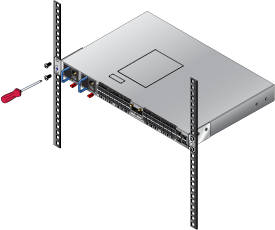
After completing the two-post rack mount, proceed to Cabling the Switch.
Four-Post Rack Mount
The switch is mounted onto a four-post rack by assembling two rails onto the rear posts, sliding the switch onto the rails, and securing the switch to the front posts.
The installation kit provides the following four-post mounting parts:
- 2x mounting brackets
- 2x rail-rods
- 2x rail-slides
The rail-rods and rail-slides assemble into two identical slide-rails.
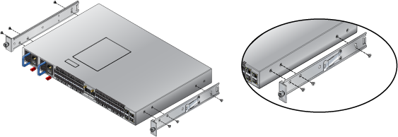
Attaching Mounting Brackets to the Chassis
- Use the screws to attach the brackets to the chassis.
Figure 3. Attaching Mounting Brackets to the Switch Chassis
Assembling the Rails onto the Equipment Rack
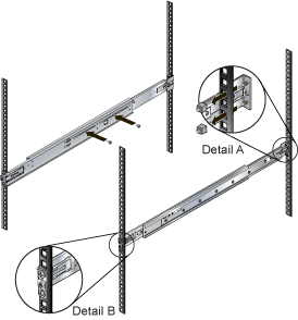
Rail-rods and rail-slides assemble into two identical rails. Each rail connects a front post to a rear post. When the rails are installed, the switch slides on the rails into the rack. Each bracket includes a screw that attaches the switch to the rail.
This procedure attaches the rails to a four post rack:
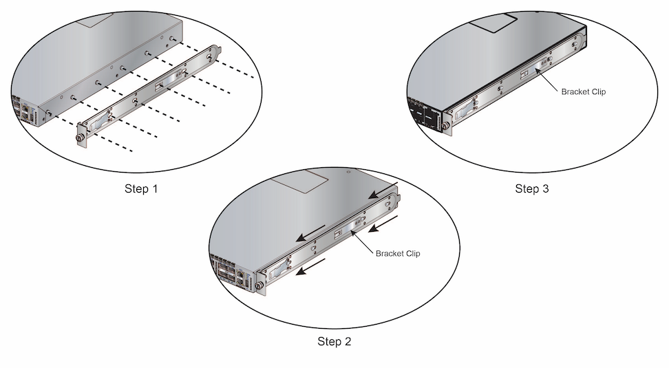
- Slide a rail-rod into a rail-slide (Figure 5 - Assembling the Rails) until the rail clip makes an audible click.
Note: The rail clip prevents the extension of the rail beyond the maximum supported distance between the front and rear rack posts.
Figure 5. Assembling the Rails
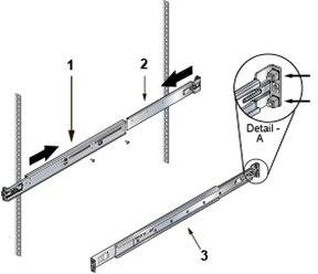
1 Rail Slide 3 Rail (assembled) 2 Rail Rod A Rack Plugs - Repeat Step 1 through Step 3 for the left posts. Ensure the rails are on the same horizontal level.
Figure 6. Attaching the Rails
Attaching the Switch to the Rack
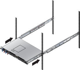
- Lift the switch into the rack and insert the mounting brackets into the slide rails (Figure 7 - Inserting the Switch onto the Rails).
Figure 7. Inserting the Switch onto the Rails
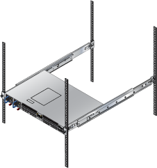
- Attach the bracket flanges to the rack post using the quick-release thumb screws supplied with the brackets (Figure 8 - Attaching the Switch to the Rack Posts ).
Figure 8. Attaching the Switch to the Rack Posts
After completing the four-post rack mount, proceed to Cabling the Switch.