Status Indicator LEDs
The following topics are covered in this section:
System-Level Status Indicator LEDs
Status indicator LEDs are located on the chassis, along with components like PSUs and fan modules. LEDs are located on the front (Front Panel) and the rear (Rear Panel) of the switch.
The following topics are covered in this section:
System Status Indicator LED
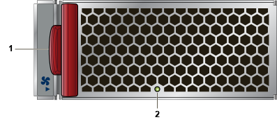
Figure 1 - System Status and Fan Status Indicators display the system and the fan status LEDs.

| 1 | System status LED | 2 | Fan status LED |
| LED Name | LED State | Device Status |
|---|---|---|
| System Status LED | Blinking Green | System is powering up. |
| Green | Normal operations. Due to power supply and fan redundancy, this LED will remain green if a single fan or power supply is missing or in a failed state. | |
| Blue | The locater function is active. | |
| Amber | Two or more fans (any combination of fan modules or PSU fans) are disconnected or malfunctioning. The switch will automatically execute a “graceful shutdown” shortly. |
Fan Status Indicator LED
Figure 1 - System Status and Fan Status Indicators display the fan status LED for the system.
| LED Name | LED State | Device Status |
|---|---|---|
| Fan Status LED | Green | All fan and power modules are operating normally. |
| Amber | Single fan module is removed or malfunctioning. It is also amber when a PSU is completely removed or has a stuck fan rotor. | |
| Red | Two or more fans (any combination of fan modules or PSU fans) are disconnected or malfunctioning. The switch will automatically execute a “graceful shutdown” shortly. |
Port Status Indicator LEDs
Port LEDs, located in the vicinity of their corresponding ports, provide a link and operational status. Figure A-2 displays a representative Port LED location on the DCS-7020SR-32C2 switch.

| 1 | Port LED | 2 | Port number |
Table 3 - Port LED States (Front) provides status conditions that correspond to port LED states. Port LED behavior for QSFP+ and SFP+ ports is consistent.
| LED State | Status |
|---|---|
| Off | Port link is down. |
| Green | Port link is up. |
| Yellow | Port is software disabled. |
| Flashing Yellow | Port failed diagnostics. |
Component Status Indicators
The following topics are covered in this section:
Fan Module Status LED
Each fan and power supply module has an LED that reports the module status. Fan module status LED is on the fan module (Figure 3 - Fan Module Status LED ) and is different from the system-level fan status LED (Fan Status Indicator LED).
| 1 | Release lever | 2 | Fan module LED |
Table 4 - Fan Module Status LED States provides status conditions that correspond to fan module status LED states.
| LED State | Status |
|---|---|
| Off | The fan module is not detected. If it is inserted, it may not be seated properly. |
| Green | The fan is operating normally. This LED state is exclusive to its fan module and independent of the states of its neighboring fans and power supplies. |
| Red | The fan has failed. |
PSU Module Status LED
The AC power supply module status LEDs are on the power supply modules (Figure 4 - AC Power Supply Status LED ).
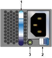
| 1 | Power supply handle | 3 | Power supply status LED |
| 2 | Power supply release lever |
Table 5 - AC Power Supply Status LED States provide status conditions that correspond to the AC power supply status LED states.
| Power Supply State | PWR-400AC |
|---|---|
| Input power present Normal operation | Green |
| Input power present Power Supply fault | Yellow |
| No Input power Supply installed in chassis | Blinking Yellow |
| Input power present Supply not installed in chassis | Blinking Green |