Status Indicators
Supervisor Module
- One serial console port.
- Two Ethernet management ports (one RJ-45, one optical.)
- Two USB ports.
- One clock input port.
- Several system-level status indicator LEDs (see System Level Status Indicator LEDs: DCS-7800-SUP-D.)
System Level Status Indicator LEDs: DCS-7800-SUP-D
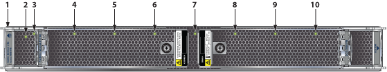
The system status indicator LEDs are shown in Figure 1.
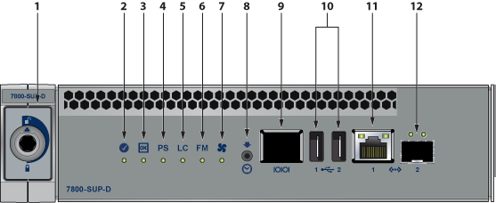
| 1 | Locking mechanism | 5 | Linecard status LED | 9 | RJ-45 Serial management port |
| 2 | Supervisor status LED | 6 | Fabric Module status LED | 10 | USB Ports |
| 3 | Supervisor active status LED | 7 | Fan status LED | 11 | RJ-45 Ethernet management port |
| 4 | PSU status LED | 8 | Clock In | 12 | SFP Ethernet management port |
Supervisor Status LEDs
Supervisor Status LED States interprets the states of the supervisor status LEDs for both the active and the redundant supervisor modules.
| Supervisor and System Condition (1) | LED Name and State | |||||||
|---|---|---|---|---|---|---|---|---|
| Status | Active | Power Supply (PSU) | Linecard (LC) | Fabric Module (FM) | Fan Module | Ethernet Port | ||
| Link (Left) | Activity (Right) | |||||||
| No power, failed, or improperly inserted. | Off | Off | Off | Off | Off | Off | Off | Off |
| Booting | Blinking Green | Off | Off | Off | Off | Off | Off | Off |
| Beacon Request Locate | Blue | Off | Off | Off | Off | Off | Off | Off |
| Normal Active Operation (Master Supervisor) System Status: Good | Green | Green | Green | Green | Green | Green | (2) | (2) |
| Redundant Supervisor (Active-Standby) Status: Good | Green | Off | Off | Off | Off | Off | Off | Off |
| Forced fail-over to redundant supervisor (Not active) Status: Bad | Red | Off | Off | Off | Off | Off | Off | Off |
| Supervisor active and operating normally; No PSUs, LCs, FMs, or Fan Modules present or powered | Green | Green | Off | Off | Off | Off | Off | Off |
| Supervisor active, Status: PSU failure (one or more) - no AC input, DC output, Over current or not enough PSUs present | Green | Green | Red | (3) | (3) | (3) | (2) | (2) |
| Supervisor active, Status: LC failure (one or more) | Green | Green | (3) | Red | (3) | (3) | (2) | (2) |
| Supervisor active, Status: FM failure (one or more) | Green | Green | (3) | (3) | Red | (3) | (2) | (2) |
| Supervisor active, Status: Fan Module failure (one or more) or not present | Green | Green | (3) | (3) | (3) | Red | (2) | (2) |
| Supervisor active, Ethernet port linked with activity | Green | Green | (3) | (3) | (3) | (3) | Green | Green |
| Supervisor active, Ethernet port linked with no activity | Green | Green | (3) | (3) | (3) | (3) | Green | Off |
| Supervisor active, Ethernet port not linked | Green | Green | (3) | (3) | (3) | (3) | Off | Off |
1 Assumes a redundant supervisor is present.
2 Depends on port operation.
3 Green for normal operation, red if no corresponding component is powered or present.
Linecard Module Indicators
Each linecard module provides one status LED plus LEDs for each port on the card. Linecard Status LED shows a representative linecard. The figures in linecards indicate the location of the LEDs on each linecard.
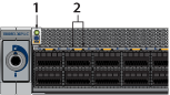
| 1 | Linecard status LED |
| 2 | Port status LED |
Linecard Status LED States interprets the states of the status LED.
| LED State | Status |
|---|---|
| Off | Linecard not inserted. |
| Green | Linecard operating normally. |
| Yellow (amber/orange) | Linecard administratively shut down or booting up. |
| Red | Linecard has failed. |
| Red (blinking) | Locator function is enabled. |
- Each LED corresponds to a module.
- A set of four LEDs correspond to each module. The first LED in the set reports status when the module is programmed as a 40G port. When the module is programmed as four 10G or 100G ports, each port is assigned to an LED within the set.
- For linecards that support OSFP and QSFP-DD ports with one LED per port, Linecard Port LED States interpret the port LED states.
Table 3. Linecard Port LED States LED State Status Off Port link is down for all enabled interfaces. Green Port link is up for any enabled interface. Yellow (amber/orange) Port is disabled in the software. Flashing yellow (amber/orange) Locator function is enabled on an interface.
Fabric Module Status Indicators
Fabric Status LEDs are on fan-fabric modules. The Rear Panel displays the position of these modules on the rear of each switch. The following figure displays the fan status and fabric status LEDs on the DCS-7804 switch. Figure 5 display fan status and fabric status LEDs on the DCS-7808 and DCS-7816 switches.
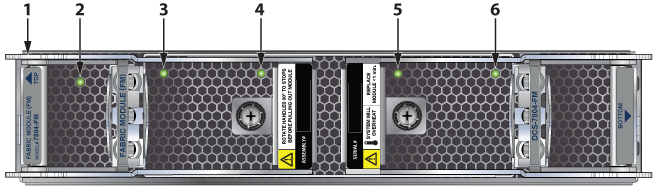
| 1 | Fabric module top | 3 | Fan module 1 status LED | 5 | Fan module 3 status LED |
| 2 | Fabric module status LED | 4 | Fan module 2 status LED | 6 | Fan module 4 status LED |
The following figure displays the LEDs for the fan status and fabric status on the DCS-7812 switch.
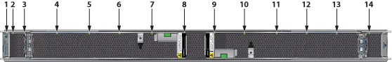
| 1 | Fabric module top | 6 | Fan module 4 status LED | 11 | Fan module 8 status LED |
| 2 | Fabric module status LED | 7 | Fan module 5 status LED | 12 | Fan module 9 status LED |
| 3 | Fan module 1 status LED | 8 | Fan module 6 status LED | 13 | Fan module 10 status LED |
| 4 | Fan module 2 status LED | 9 | Fabric module ejector lever | 14 | Fan module 11 status LED |
| 5 | Fan module 3 status LED | 10 | Fan module 7 status LED |
| 1 | Fabric module top | 5 | Fan module 3 status LED | 9 | Fan module 7 status LED |
| 2 | Fabric module status LED | 6 | Fan module 4 status LED | 10 | Fan module 8 status LED |
| 3 | Fan module 1 status LED | 7 | Fan module 5 status LED | ||
| 4 | Fan module 2 status LED | 8 | Fan module 6 status LED |
For the 7816 switch, the lower fabric module fan modules are numbered 9 through 16.
- DCS-7816R3-FM and DCS-7808R3-FM look similar. Check the label before populating the chassis.
- For the DCS-7816 switch, the top and bottom fabric modules form one logical fabric module. Both physical modules in a logical pair turn off if either loses power.
- The show module command lists the serial number (SN) of only the bottom-slot Fabric Module.
Fan Status and Fabric Status LEDs on the Rear Panel interpret the state of the fan and fabric status LED.
| LED State | Status |
|---|---|
| Off | Module inserted, but the status is unknown. |
| Green | Module operating normally. |
| Red | Module failed. |
Power Supply Status Indicators
PWR-D1-3041-AC-BLUE
The power supply status LEDs are on the power supply modules. Figure 6 displays all the LEDs on the PWR-D1-3041-AC-BLUE AC power supply.
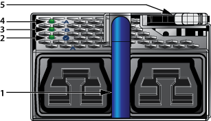
| 1 | Handle | 4 | AC_A LED |
| 2 | Output | 5 | Release |
| 3 | AC_B LED |
AC Power Supply Status LED States interprets the AC power supply setup for LED status indicators.
| Power Supply Status | LED Name | ||
|---|---|---|---|
| AC_A | AC_B | Output | |
| Normal Operation(1) | Green | Off | Green |
| No AC Input - Single PSU | Off | Off | Off |
| No AC Input - Parallel PSUs | Yellow | Yellow | Off |
| Standby Mode | Green | Off | Blinking Green(2) |
| AC_A Fail | Yellow | Green | Green |
| AC_B Fail | Green | Yellow | Green |
| Power Supply Fault | Green | Off | Yellow |
| Boot Loader | Off | Off | Blinking(3) |
1 AC_A is the primary input.
2 1 Hz, 50% Duty Cycle.
3 1 Hz, 50% Green, 50% Yellow.
PWR-D2-3041-DC-BLUE
The power supply status LEDs are on the power supply modules. Figure 7 displays all the LEDs on the PWR-D2-3041-DC-BLUE DC power supply.
.png)
| 1 | Status LED (Output) | 4 | Input_A LED | 7 | Battery return terminal |
| 2 | Release | 5 | Protective earth terminal | 8 | -48V terminal |
| 3 | GND terminal | 6 | Input_B LED |
DC Power Supply Status LED States interprets the DC power supply setup for LED status indicators.
| Power Supply Status | LED Name | ||
|---|---|---|---|
| Input_A | Input_B | Output | |
| Normal Operation | Green | Green | Green |
| No DC Input - Single PSU | Off | Off | Off |
| No DC Input - Parallel PSUs
(Standby Mode 2) |
Yellow | Yellow | Off |
| Standby Mode 1 | Green | Green | Blinking Green(1) |
| Input_A Fail | Yellow | Green | Green |
| Input_B Fail | Green | Yellow | Green |
| Power Supply Fault | Green | Green | Yellow |
| Boot Loader | Off | Off | Blinking(2) |
1 1 Hz, 50% Duty Cycle.
2 1 Hz, 50% Green, 50% Yellow.
3 States can be combined.