Front Panel
This section displays the front panel of all switches covered by this guide.
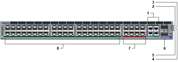
| 1 | 25G SFP ports | 2 | System status LED | 3 | Fan status LED |
| 4 | Power supply 1 status LED | 5 | Power supply 2 status LED | 6 | 100G QSFP ports |
| 7 | 5G PoE+ ports | 8 | 2.5G PoE+ ports |
Note: The 2.5G ports are PoE+ (30 W max), and the 5G ports are PoE+ (60 W max).
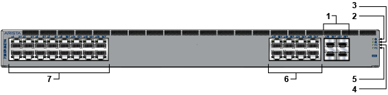
| 1 | 25G SFP ports | 2 | System status LED | 3 | Fan status LED |
| 4 | Power supply 1 status LED | 5 | Power supply 2 status LED | 6 | 5G PoE+ ports |
| 7 | 2.5G PoE+ ports |
Note: The 2.5G ports are PoE+ (30 W max) and the 5G ports are PoE+ (60 W max).
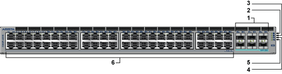
| 1 | 25G SFP ports | 2 | System status LED | 3 | Fan status LED |
| 4 | Power supply 1 status LED | 5 | Power supply 2 status LED | 6 | 1G PoE+ ports |
Note: The 1G ports are PoE+ (30 W max).
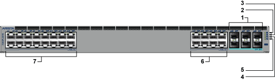
| 1 | 25G SFP ports | 2 | System status LED | 3 | Fan status LED |
| 4 | Power supply 1 status LED | 5 | Power supply 2 status LED | 6 | 1G PoE+ port |
| 7 | 1G PoE+ ports |
Note: The 1G ports are PoE+ (30 W max).
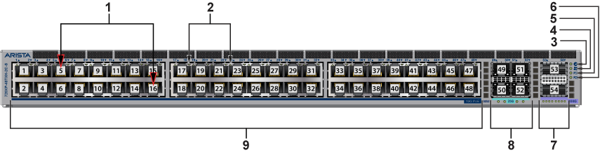
| 1 | RJ45 ports | 2 | Connection status LED | 3 | System status LED |
| 4 | Fan status LED | 5 | Power supply 1 status LED | 6 | Power supply 2 status LED |
| 7 | 100G QSFP ports | 8 | 25G SFP ports | 9 | 10G PoE+ ports |
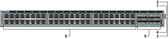
| 1 | System status LED | 2 | Fan status LED | 3 | Power supply 1 status LED |
| 4 | Power supply 2 status LED | 5 | 25G SFP ports | 6 | 2.5G PoE+ ports |
Note: The 2.5G ports are PoE+ (60 W max).
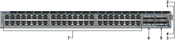
| 1 | System status LED | 2 | Fan status LED | 3 | Power supply 1 status LED |
| 4 | Power supply 2 status LED | 5 | 10G SFP ports | 6 | 25G SFP ports |
| 7 | 2.5G PoE+ ports |
Note: The 2.5G ports are PoE+ (30 W max).