Taiwan RoHS Information
This section provides the Taiwan RoHS information for switches this guide covers.
This section provides the Taiwan RoHS information for switches this guide covers.
This section lists the Regulatory Model Numbers (RMNs), where applicable, for the product models for the switches described in this document.
| Regulatory Model Number (RMN) | Product Number(s) |
|---|---|
| AN1708 | DCS-7280PR3-24 DCS-7280PR3K-24 |
| AN1730 | DCS-7280DR3-24 DCS-7280DR3K-24 |
| AN1715 | DCS-7280CR3-32P4 DCS-7280CR3K-32P4 DCS-7280CR3K-32P4A |
| AN1731 | DCS-7280CR3-32D4 DCS-7280CR3K-32D4 DCS-7280CR3K-32D4A |
| AN1742 | DCS-7280CR3-36S DCS-7280CR3K-36S DCS-7280CR3K-36A |
| AN1718 | DCS-7280CR3-96 DCS-7280CR3K-96 |
| AN1728 | DCS-7280SR3-48YC8 DCS-7280SR3K-48YC8 DCS-7280SR3K-48YC8A |
| AN1741 | DCS-7280SR3-40YC6 DCS-7280SR3E-40YC6-M |
| AN1743 | DCS-7280TR3-40C6 |
Review the following considerations when installing the device.
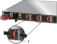
The following steps are required when removing power supplies from a switch.
_Numb.png)
| 1 | Release lever | 2 | Remove PSU |
switch# show environment power
The command output will list the power supplies in operation and should include the one you replaced.
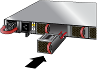
The following steps are required when removing or replacing fans from a switch.
| 1 | Release lever |
You must make space for installing the fan module by removing an existing one.
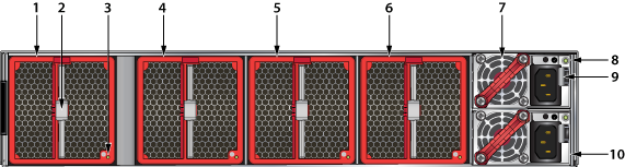
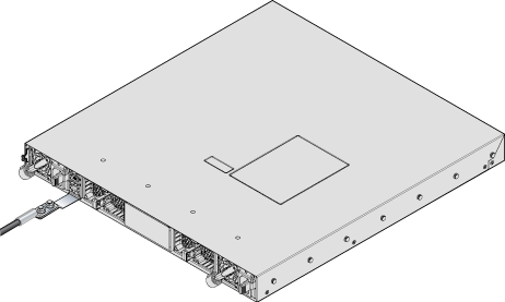
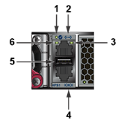
All switches this guide covers use one of the rear panels shown below. Depending on the installed power supply module, the appearance could differ from those shown. Some of the PSUs have a velcro strap for cable management.
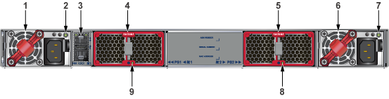
| 1 | Power supply 1 | 4 | Fan module 1 | 7 | Power supply 2 status LED |
| 2 | Power supply 1 status LED | 5 | Fan module 2 | 8 | Fan module 2 status LED |
| 3 | Management ports | 6 | Power supply 2 | 9 | Fan module 1 status LED |
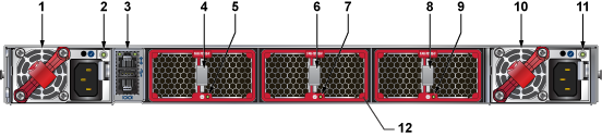
| 1 | Power supply module 1 | 5 | Fan module 1 status LED | 9 | Fan module 3 status LED |
| 2 | Power supply module 1 status LED | 6 | Fan module 2 release | 10 | Power supply module 2 |
| 3 | Management ports | 7 | Fan module 2 status LED | 11 | Power supply module 2 status LED |
| 4 | Fan module 1 release | 8 | Fan module 3 release | 12 | Fan module bezel1 |
.png)
| 1 | Fan module 1 | 4 | Fan module 4 | 7 | Earth grounding pad |
| 2 | Fan module 2 | 5 | Power supply module 1 | ||
| 3 | Fan module 3 | 6 | Power supply module 2 |
| 1 | Fan Module 1 | 5 | Fan Module 3 | 9 | Release |
| 2 | Release | 6 | Fan Module 4 | 10 | Power Supply Module 2 |
| 3 | Status LED | 7 | Power Supply Module 1 | ||
| 4 | Fan Module 2 | 8 | Status LED |
1. Bezel color indicates airflow direction.
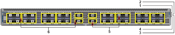
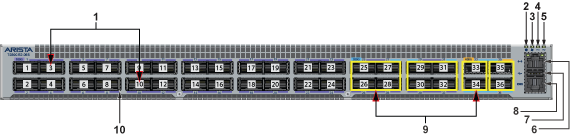
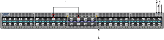
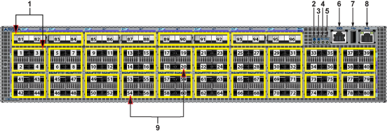
This section displays the front panel of all switches covered by this guide.
The port speed groups support breakout configurations that could depend on the EOS version.
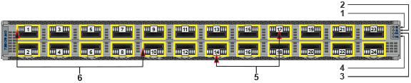
| 1 | System status LED | 3 | Power supply 1 status LED | 5 | Port numbers |
| 2 | Fan status LED | 4 | Power supply 2 status LED | 6 | Port-speed group |
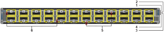
| 1 | System status LED | 3 | Power supply 1 status LED | 5 | Port numbers |
| 2 | Fan status LED | 4 | Power supply 2 status LED | 6 | Port-speed group |
| 1 | System status LED | 3 | Power supply 1 status LED | 5 | Port numbers |
| 2 | Fan status LED | 4 | Power supply 2 status LED | 6 | Port-speed group |
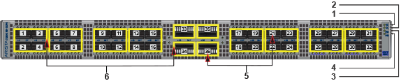
| 1 | System status LED | 3 | Power supply 1 status LED | 5 | Port numbers |
| 2 | Fan status LED | 4 | Power supply 2 status LED | 6 | Port-speed group |
| 1 | Port numbers | 5 | Power supply 2 status LED | 9 | Port Speed Groups |
| 2 | System status LED | 6 | Ethernet Management port | 10 | Port Status LED |
| 3 | Fan status LED | 7 | USB port | ||
| 4 | Power supply 1 status LED | 8 | Console port (serial) |
| 1 | Port numbers | 3 | Fan status LED | 5 | Power supply 2 status LED |
| 2 | System status LED | 4 | Power supply 1 status LED | 6 | Port status LED (port 25) |
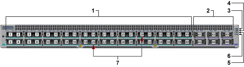
| 1 | 25G ports | 4 | Fan status LED | 7 | Port numbers |
| 2 | 100G ports | 5 | Power supply 1 status LED | ||
| 3 | System status LED | 6 | Power supply 2 status LED |
| 1 | Port speed groups | 4 | Power supply 1 status LED | 7 | USB port |
| 2 | System status LED | 5 | Power supply 2 status LED | 8 | Ethernet Management port |
| 3 | Fan status LED | 6 | Console port (serial) | 9 | Port numbers |
This section lists the installation parts of the switch accessory kit.
Each switch provides an accessory kit containing the parts required to install the switch. A four-post rack mount is recommended for all switches. Use the rack-mount parts included with your switch for mounting. Rails from different kit SKUs may look similar but incompatible with extension kits for longer switches. Depending on the PSU, C13/14, C19/20, or SAF-D type power cables are included in the accessory kit.
This section describes the components included with the accessory kits available with the switches. Not all kits ship with all switches. Use only the parts shipped with the switch or optional, compatible kits. Do not mix parts from incompatible kits such as KIT-7001/2 and KIT-7101/2.
The kit supports rack depths of twenty-two to thirty-two inches for four-post rack mounting of 1RU switches. The kit includes two-post rack mount parts. If needed, only a center mount is recommended for two-post mounting.
| Assembly Part Number | Description | Quantity |
|---|---|---|
| ASY-00921 | Two-post brackets | 2 |
| IEC-320/C13-C14, 13 A, 250 V, 2 meter | 2 | |
| RJ45 Patch Panel Cable, 2 meter | 1 | |
| RJ45 to DB9 Adapter Cable, 2 meter | 1 | |
| Identity tag | 1 | |
| ASY-01098-05 | Rack ear with captive thumb screw | 2 |
| ASY-00905-0X | Front rack rail with guide block | 2 |
| ASY-00916-0X | Rear sliding rack rail with guide block | 2 |
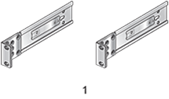
| 1 | Two-post rack mount parts |

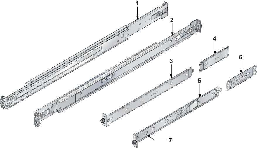
| 1 | Rail-slide | 3 | Rack plugs (detail) |
| 2 | Rail-rod | 4 | Rail (assembled) |
This kit includes extended rails to support mounting some 1RU switches in thirty-two to forty-two-inch rack depths. It is not compatible with deep chassis adapters.
| Assembly Part Number | Description | Quantity |
|---|---|---|
| ASY-01098 | Four-post brackets | 2 |
The kit supports rack depths of twenty-two to thirty-two inches for four-post rack mounting of 2RU switches. The kit includes two-post rack mount parts. If needed, only a center mount is recommended for two-post mounting.
| Assembly Part Number | Description | Quantity |
|---|---|---|
| ASY-00920 | Two-post brackets | 2 |
| IEC-320/C13-C14, 13 A, 250 V, 2 meter | 2 | |
| RJ45 Patch Panel Cable, 2 meter | 1 | |
| RJ45 to DB9 Adapter Cable, 2 meter | 1 | |
| ASY-01098-05 | Rack ear with captive thumb screw | 2 |
| ASY-00905-0X | Front rack rail with guide block | 2 |
| ASY-00916-0X | Rear sliding rack rail with guide block | 2 |
The kit supports rack depths of twenty-two to thirty-two inches for four-post rack mounting of 1RU switches. It is compatible with the deep chassis adapter that supports heavier and longer switches.
| Assembly Part Number | Description | Quantity |
|---|---|---|
| IEC-320/C13-C14, 13 A, 250 V, 2 meter | 2 | |
| RJ45 Patch Panel Cable, 2 meter | 1 | |
| RJ45 to DB9 Adapter Cable, 2 meter | 1 | |
| Identity tag | 1 | |
| ASY-05581 | Rack ear with captive thumb screw | 2 |
| ASY-05578 | Front rack rail with guide block | 2 |
| ASY-00916 | Rear sliding rack rail with guide block | 2 |
The kit supports rack depths of twenty-two to thirty-two inches for four-post rack mounting of 1RU switches. It includes the deep chassis adapter required to support heavier and longer switches.
| Assembly Part Number | Description | Quantity |
|---|---|---|
| IEC-320/C13-C14, 13 A, 250 V, 2 meter | 2 | |
| RJ45 Patch Panel Cable, 2 meter | 1 | |
| RJ45 to DB9 Adapter Cable, 2 meter | 1 | |
| Identity tag | 1 | |
| ASY-05581 | Rack ear with captive thumb screw | 2 |
| ASY-05578 | Front rack rail with guide block | 2 |
| ASY-00916 | Rear sliding rack rail with guide block | 2 |
| ASY-05576 | Deep chassis adapter | 2 |
| 1 | Rack rail | 4 | Deep chassis adapter | 7 | Double triangle symbol |
| 2 | Rack rail | 5 | Rack ear with captive thumb screw | ||
| 3 | Rack ear with captive thumb screw | 6 | Deep chassis adapter |
The kit supports rack depths of twenty-two to thirty-two inches for four-post rack mounting of 1RU switches. It supports the deep chassis adapter required to support heavier and longer switches.
| Assembly Part Number | Description | Quantity |
|---|---|---|
| IEC-320/C19-C20, 16 A, 250 V, 2 meter | 2 | |
| RJ45 Patch Panel Cable, 2 meter | 1 | |
| RJ45 to DB9 Adapter Cable, 2 meter | 1 | |
| Identity tag | 1 | |
| ASY-05581 | Rack ear with captive thumb screw | 2 |
| ASY-05578 | Front rack rail with guide block | 2 |
| ASY-00916 | Rear sliding rack rail with guide block | 2 |
| Deep chassis adapter | 2 |
The kit supports rack depths of twenty-two to thirty-two inches for four-post rack mounting of 1RU switches. It includes the deep chassis adapter required to support heavier and longer switches.
| Assembly Part Number | Description | Quantity |
|---|---|---|
| IEC-320/C19-C20, 16 A, 250 V, 2 meter | 2 | |
| RJ45 Patch Panel Cable, 2 meter | 1 | |
| RJ45 to DB9 Adapter Cable, 2 meter | 1 | |
| Identity tag | 1 | |
| ASY-05581 | Rack ear with captive thumb screw | 2 |
| ASY-05578 | Front rack rail with guide block | 2 |
| ASY-00916 | Rear sliding rack rail with guide block | 2 |
| ASY-05576 | Deep chassis adapter | 2 |
The kit supports rack depths of twenty-two to thirty-two inches for four-post rack mounting of 2RU switches.
| Assembly Part Number | Description | Quantity |
|---|---|---|
| IEC-320/C13-C14, 13 A, 250 V, 2 meter | 2 | |
| RJ45 Patch Panel Cable, 2 meter | 1 | |
| RJ45 to DB9 Adapter Cable, 2 meter | 1 | |
| Identity tag | 1 | |
| ASY-06132 | Rack ear with captive thumb screw | 2 |
| ASY-03765 | Front rack rail with guide block | 2 |
| ASY-03767 | Rear sliding rack rail with guide block | 2 |
The kit supports rack depths of twenty-two to thirty-two inches for four-post rack mounting of 2RU switches.
| Assembly Part Number | Description | Quantity |
|---|---|---|
| IEC-320/C19-C20, 16 A, 250 V, 2 meter | 2 | |
| RJ45 Patch Panel Cable, 2 meter | 1 | |
| RJ45 to DB9 Adapter Cable, 2 meter | 1 | |
| Identity tag | 1 | |
| ASY-06132 | Rack ear with captive thumb screw | 2 |
| ASY-03765 | Front rack rail with guide block | 2 |
| ASY-03767 | Rear sliding rack rail with guide block | 2 |
| Quantity | Description |
|---|---|
| 2 | Power cables: IEC-320/C13-C14, 13 A, 250 V, 2 m |
| 2 | Power cables: IEC-320/C19-C20, 16 A, 250 V, 2 m |
| 1 | RJ-45 Patch Panel Cable |
| 1 | RJ-45 to DB9 Adapter Cable |
All provided power cables are for use only with Arista products.

| SKU | Description |
|---|---|
| KIT-GND-EXT-1RU1 | Ground extender kit for NEBS compliance |
| KIT-GND-EXT-2RU1 | Ground extender kit for NEBS compliance |
Reviews the switch and port indicators of the device.
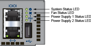
Front panel LEDs are located on the right side of the chassis and display system, fan, and power supply status.
The front panel LEDs are labeled as Figure 1 - System Status Indicators or Figure 2 - System Status Indicators. Check your device for the specific method utilized.
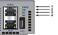
| 1 | System status LED | 3 | Power supply 1 status LED |
| 2 | Fan status LED | 4 | Power supply 2 status LED |
| 1 | System status LED | 3 | Power supply 1 status LED |
| 2 | Fan status LED | 4 | Power supply 2 status LED |
| LED Name | LED State | Device Status |
|---|---|---|
| System Status LED | Blinking Green | System is powering up. |
| Green | Normal operations. Due to power supply and fan redundancy, this LED will remain green if a single fan or power supply is missing or in a failed state. | |
| Blue | The locator function is active. | |
| Amber | Two or more fans (any combination of fan modules or PSU fans) are disconnected or malfunctioning. The switch will automatically execute a “graceful shutdown” shortly. | |
| Fan Status LED | Green | All fan and power modules are operating normally. |
| Amber | Single fan module is removed or malfunctioning. It is also amber when a PSU is completely removed or has a stuck fan rotor. | |
| Red | Two or more fans (any combination of fan modules or PSU fans) are disconnected or malfunctioning. The switch will automatically execute a “graceful shutdown” shortly. | |
| PSU [1:2] Status LED | Green | PSU is functioning and fully operational. AC is present, Aux output is ON, and Main output is ON. |
| Off | PSU has been removed or is not operating properly due to the AC cord being unplugged, its fan rotor being stuck, or an internal fault. |
Port LEDs near their corresponding ports provide a link and operational status.
The following figure displays the Port LED location on the DCS-7050QX-32S switch.
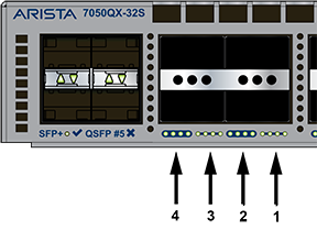
| 1 | Port 4 LEDs | 3 | Port 2 LEDs |
| 2 | Port 3 LEDs | 4 | Port 1 LEDs |
Table 2 - Port LED States (Front) provides status conditions corresponding to port LED states. Port LED behavior for QSFP+ and SFP+ ports is consistent.
| LED State | Status |
|---|---|
| Off | The port link is down. |
| Green | The port link is up. |
| Yellow | The port is software disabled. |
| Flashing Yellow | The port failed diagnostics. |
You can access the fan and power supply modules from the rear panel.
Each fan and power supply module contains an LED that reports the module status.
Fan Status LEDs are on the fan modules, as displayed in Figure 4 - Fan Status LED.
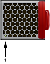
| 1 | Fan module status LED |
Table 3 - Fan Status LED States (Rear) provide conditions corresponding to fan status LED states.
| LED State | Status |
|---|---|
| Off | The fan module is not detected. If it is inserted, it may not be seated properly. |
| Green | The fan is operating normally. This LED state is exclusive to its fan module and independent of the states of its neighboring fans and power supplies. |
| Red | The fan has failed. |
The AC Power Supply Status LEDs are on the power supply modules, as displayed in the Figure 5 - AC Power Supply Status LED.
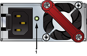
| 1 | Power supply status LED |
Table 4 - AC Power Supply Status LED States (Rear) provides conditions corresponding to the AC power supply status LED states.
| Power Supply State | PWR-500AC-F PWR-500AC-R | PWR-745AC-F PWR-745AC-R | PWR-747AC-F PWR-747AC-R |
|---|---|---|---|
| Input power present Normal operation | Green | Green | Green |
| Input power present Power Supply fault | Yellow | Yellow | Yellow |
| No Input power Supply installed in chassis | Off | Off | Off |
| Input power present Supply not installed in chassis | Green | Green | Green |
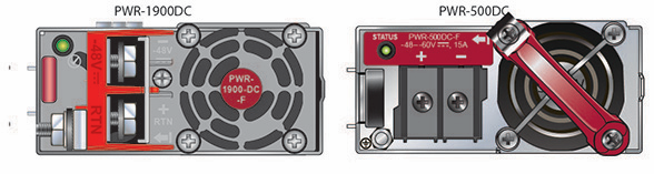
The DC Power Supply Status LEDs are on the modules, as displayed in the Figure 6 - DC Power Supply Status LED.

Table 5 - DC Power Supply Status LED States (Rear) provides status conditions that correspond to the DC power supply status LED states.
| Power Supply State | PWR-500DC-F,PWR-500DC-R | PWR-1900-DC | PWR-2411-DC |
|---|---|---|---|
| Input power present Normal operation | Green | Green | Green |
| Input power present Power Supply fault | Blinking Yellow | Blinking Yellow | Blinking Yellow |
| No Input power Supply installed in chassis | Off | Off | Off |
| Input power present Supply not installed in chassis | Blinking Yellow | Blinking Yellow | Blinking Yellow |
Arista switches ship from the factory in Zero Touch Provisioning (ZTP) mode. ZTP configures the switch without user intervention by downloading a startup configuration file or a boot script from a location specified by a DHCP server.
To manually configure a switch, ZTP is bypassed. The initial configuration provides one username (admin) accessible only through the console port because it has no password.
When bypassing ZTP, initial switch access requires logging in as admin, with no password, through the console port. Then you can configure an admin password and other password protected usernames.
This manual configuration procedure cancels ZTP mode, logs into the switch, assigns a password to admin, assigns an IP address to the management port, and defines a default route to a network gateway.
The device is in Zero Touch Provisioning mode and is attempting to
download the startup-config from a remote system. The device will not
be fully functional until either a valid startup-config is downloaded
from a remote system or Zero Touch Provisioning is cancelled. To cancel
Zero Touch Provisioning, login as admin and type 'zerotouch cancel'
at the CLI.

localhost login:
localhost login: admin
localhost> zerotouch cancel
Arista EOS
localhost login: admin
Last login: Fri Mar 15 13:17:13 on console
localhost> enable
localhost# config
localhost(config)# username admin secret pxq123
localhost(config)# ip route 0.0.0.0/0 192.0.2.1
localhost(config)# interface management 1
localhost(config-if-Ma1/1)# ip address 192.0.2.8/24
localhost# copy running-config startup-config
When the management port IP address is configured, use this command to access the switch from a host, using the address configured in Step 9.
ssh admin@192.0.2.8
Refer to the Arista Networks User Manual for complete switch configuration information.
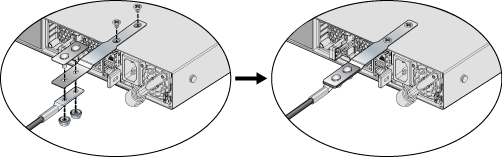
After mounting the switch into the rack, connect the switch to the data center ground.
Figure 1 - Earth Grounding Adapter (DCS-7280CR3-32P4 shown) displays the location of the grounding assembly on the chassis for DCS-7280CR3-32P4 and similar switches that use the KIT-GND-EXT-1RU grounding kit. For the 2RU switches, the grounding location is at the rear panel of the switches or on the side using the KIT-GND-EXT-2RU grounding kit.
Grounding wires and grounding lugs (M4 x 0.7) are not supplied. Wire size should meet local and national installation requirements. Commercially available 6 AWG wire is recommended for installations in the US.
À la terre et de mise à la terre fils cosses (M4 x 0.7) ne sont pas fournis. Calibre des fils doit satisfaire des exigences de l’installation locale et nationale. Disponible dans le commerce 6 fils AWG est recommandé pour les installations aux États-Unis.
In the following steps, assemble and attach a grounding assembly to the chassis before mounting it into the rack.
| Switch | Grounding Kit Adapter |
|---|---|
| DCS-7280R3 Series switches | |
| DCS-7280PR3-24 | KIT-GND-EXT-1RU |
| DCS-7280PR3K-24 | KIT-GND-EXT-1RU |
| DCS-7280DR3-24 | KIT-GND-EXT-1RU |
| DCS-7280DR3K-24 | KIT-GND-EXT-1RU |
| DCS-7280CR3-32P4 | KIT-GND-EXT-1RU |
| DCS-7280CR3K-32P4 | KIT-GND-EXT-1RU |
| DCS-7280CR3K-32P4A | KIT-GND-EXT-1RU |
| DCS-7280CR3-32D4 | KIT-GND-EXT-1RU |
| DCS-7280CR3K-32D4 | KIT-GND-EXT-1RU |
| DCS-7280CR3K-32D4A | KIT-GND-EXT-1RU |
| DCS-7280CR3-36S | KIT-GND-EXT-1RU |
| DCS-7280CR3K-36S | KIT-GND-EXT-1RU |
| DCS-7280CR3K-36A | KIT-GND-EXT-1RU |
| DCS-7280SR3-48YC8 | KIT-GND-EXT-1RU |
| DCS-7280SR3K-48YC8 | KIT-GND-EXT-1RU |
| DCS-7280SR3K-48YC8A | KIT-GND-EXT-1RU |
| DCS-7280SR3-40YC6 | KIT-GND-EXT-1RU |
| DCS-7280SR3E-40YC6-M | KIT-GND-EXT-1RU |
| DCS-7280TR3-40C6 | KIT-GND-EXT-1RU |
Earth Grounding Adapter Assembly for DCS-7280CR3-32P4 shows the exploded and assembled views of using the KIT-GND-EXT-1RU grounding kit.
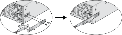
In the following steps, attach a grounding assembly KIT-GND-EXT-2RU to the side of the supported 2RU chassis before mounting it into the rack.
| Switch | Grounding Kit Adapter |
|---|---|
| DCS-7280R3 Series switches | |
| DCS-7280CR3-96 | Attach directly - right angle lug recommended |
| DCS-7280CR3K-96 | Attach directly - right angle lug recommended |
The following figure shows the exploded and assembled views of using the KIT-GND-EXT-2RU grounding kit.
You must use an approved power cord thst is compliant with local and national electrical codes or order one from Arista for use with the switch. Some power cords are shipped with each switch as part of the accessory kit.
Installation of this equipment must comply with local and national electrical codes. Consult with the appropriate regulatory agencies and inspection authorities to ensure compliance if necessary.
L'installation de cet équipement doit être conforme aux codes électriques locaux et nationaux. Consultez les agences de réglementation et les autorités d'inspection appropriées pour garantir la conformité si nécessaire.
The switch operates with two installed power supplies. At least one power supply must connect to a power source. Two circuits provide redundancy protection. The Rear Panel displays the location of the power supplies on the switch's rear panel.
Read all installation instructions before connecting the system to the power source.
Lire toutes les instructions d’installation avant de brancher le système à la source d’alimentation.
This equipment must be grounded. Never defeat the ground conductor.
Cet équipement doit être mis à la terre. Ne jamais modifier le conducteur de terre.
This unit requires overcurrent protection.
Cet appareil requiert une protection contre les surintensités.
The following AC power supplies are supported.
| PWR-511-AC | PWR-1511-AC | PWR-3001-AC |
| PWR-1011-AC | PWR-2411-AC |
The Figure 4 - AC Power Supply Example displays an AC power supply, including the power socket on the left side of the module. The AC power supply connects to a circuit providing the required power, as Table 4 - Switch Specifications (Power Draw) specified.
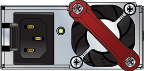
The accessory kit provides power cables for some switches.
The following DC power supplies are supported.
| PWR-500-DC | PWR-1511-DC | PWR-3001-DC |
| PWR-511-DC | PWR-1900-DC | |
| PWR-1011-DC | PWR-2411-DC |
The following image displays examples of DC power supplies.
A disconnect device must be provided as part of the installation.
Un dispositif de sectionnement doit être fourni dans le cadre de l'installation.
Ensure power is removed from DC circuits before performing any installation actions. Locate the disconnect device, circuit breakers, or fuses on DC power lines servicing the circuits. Turn off the power line circuits or remove the fuses.
Pouvoir assurer qu'il est retiré de circuits DC avant d'effectuer des actions d'installation . Localiser les disjoncteurs ou des fusibles sur les lignes de courant continu desservant les circuits. Coupez les circuits de lignes d'alimentation ou retirer les fusibles.
Wire size must comply with local and national requirements and electrical codes. Use only copper wire.
Le calibre du fil doit être conforme aux exigences locales et nationales et les codes électriques. Utiliser du fil de cuivre.
Apply ground connection to the switch first during installation and remove last when removing power.
Appliquer connexion à la terre à l'interrupteur premier lors de l'installation et de supprimer la dernière alimentation lors du débranchement.
Before installing, remove power from DC circuits by turning off the power line servicing the circuits. Prepare the stranded wiring before you begin a DC power installation.
| PSU | Wire Size(1) | Lug Type(2) | Tightening Torque | ||
|---|---|---|---|---|---|
| (AWG) | (mm2) | N•m | in.•lbs. | ||
| PWR-500-DC | 14 or larger | 2.0 or larger | ring or spade/fork | 1.0 | 9 |
| PWR-511-DC | 12 - 14 | 4.0 - 2.5 | 1.0 | 9 | |
| PWR-1900-DC | 4 - 6 | 21.2 - 13.3 | 2.7 | 24 | |
| PWR-1011-DC | 6 - 8 | 16.0 - 10.0 | 2.7 | 24 | |
| PWR-1511-DC | 4 - 6 | 25.0 - 16.0 | 2.7 | 24 | |
| PWR-2411-DC | 2 - 4 | 35.0 - 25.0 | 2.7 | 24 | |
| PWR-3001-DC | 1 - 2 | 50 - 35.0 | 4.0 | 35 | |
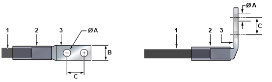
| 1 | Insulated wire | 2 | Heat-shrink tubing | 3 | Lug |
| A | 1/4” | B | 1/2” | C | 5/8” |
Figure 7 - DC PSU Connection Example displays an example of connecting a PSU. To connect a DC power supply to a power source, perform the following:
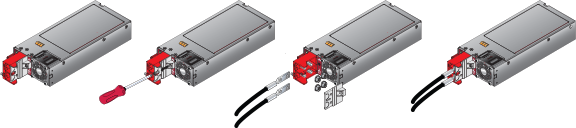
Table 4 - RJ-45 to DB-9 Connections lists the pin connections of the RJ-45 to DB-9 adapter cable.
| RJ-45 | DB-9 | RJ-45 | DB-9 | |||||
|---|---|---|---|---|---|---|---|---|
| RTS | 1 | 8 | CTS | GND | 5 | 5 | GND | |
| DTR | 2 | 6 | DSR | RXD | 6 | 3 | TXD | |
| TXD | 3 | 2 | RXD | DSR | 7 | 4 | DTR | |
| GND | 4 | 5 | GND | CTS | 8 | 7 | RTS | |
The front panel contains the console, management, and USB ports for most models. The front panel ports display the ports on the front panel of the DCS-7050QX-32S switch. The rear panel ports display the ports on the rear panel of the DCS-7280SR-48C6 switch. The front panel and rear panel display all switches this guide covers.
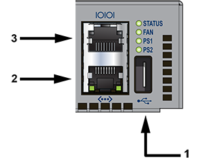
| 1 | USB port | 2 | Ethernet management port | 3 | Console serial port |
| 1 | System status LED | 3 | Activity status LED | 5 | USB port |
| 2 | Ethernet management port | 4 | Console serial port | 6 | Link status LED |
Excessive bending can damage interface cables, especially optical cables.
Flexion excessive peut endommager les câbles d’interface, notamment des câbles optiques.
The following sections detail rack mounting in two-post and four-post racks for 1 RU switches.
The rack mounting procedure is identical for all switches covered by this guide. Illustrations in this chapter depict the mounting of a DCS-7050QX-32S switch.
Les procédure de montage du bâti est identique pour tous les commutateurs visés par ce guide. Illustrations dans ce chapitre montrent le montage d’un interrupteur de DCS-7050QX-32S.
After completing the instructions for your rack type, proceed to Cabling the Switch.
To mount the switch onto a two-post rack, assemble the mounting brackets to the chassis, then attach the brackets to the rack posts. Two-post accessory kits include the following two-post mounting parts.
Each chassis side has attachment pins that align with bracket holes. Pin orientation is symmetric and equidistant, supporting bracket placements where the flange is flush with the front switch panel, flush with the rear panel, or not flush with either panel. Each bracket hole includes a key opening for placing the bracket flush with the chassis and then locking it into place.
Attachment pins must engage all three upper bracket holes.
Les goupilles de fixation doivent être bloquées tous les trois trous de la bride supérieure.
The following figure displays the front bracket alignment for attaching the switch to a two-post rack.
The following figure displays examples of improper bracket mounts for two-post rack mounts.
The following procedure attaches the two-post rack mount brackets to the chassis.
The following figures show the correct bracket attachment for a center mount.
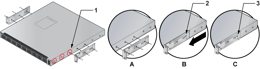
To remove the mounting bracket from the chassis, lift the front edge of the mounting bracket clip with a flathead screwdriver and slide the bracket away from the front flange (opposite from the installation direction).
This procedure attaches the switch to the rack.
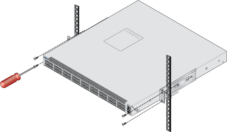
After completing the two-post rack mount, proceed to Cabling the Switch.
Mount the switch onto a four-post rack by assembling two rails onto the rear posts, sliding the switch onto the rails, and securing the switch to the front posts.
The rail rods and rail slides assemble into two identical slide rails.
Each chassis side has attachment pins that align with bracket holes. Pin orientation is symmetric and equidistant, supporting bracket placements where the flange is flush with the front switch panel, flush with the rear panel, or not flush with either panel. Each bracket hole includes a key opening for placing the bracket flush with the chassis and then locking it into place.
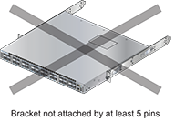
Attachment pins must engage at least five of the six bracket holes.
Goupilles de fixation doivent être lock au moins cinq des trous du six support.
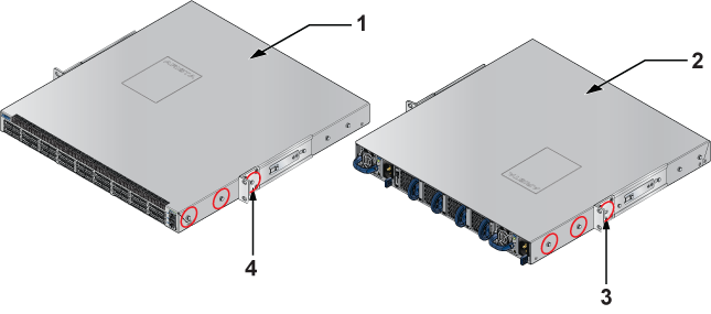
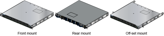
The following figure displays proper bracket mount configuration examples for four-post mounting.
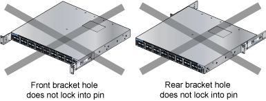
The following figure displays an example of an improper bracket mount configuration.
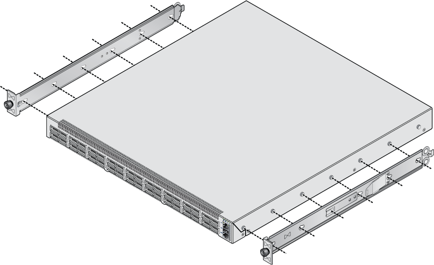
This procedure attaches mounting brackets to the switch chassis, as the preceding figure(s) depicts.
To remove the mounting bracket from the chassis, lift the front edge of the mounting bracket clip with a flathead screwdriver and slide the bracket away from the front flange (opposite from the installation direction).
The rest of the rack mounting steps are the same for KIT-7001 and KIT-7101.
Rail rods and rail slides assemble into two identical rails. Each rail connects a front post to a rear post. When the rails are installed, the switch slides on the rails into the rack. Each bracket includes a screw that attaches the switch to the rail.
Each end of an assembled rail contains two rack plugs (Figure 9 - Attaching the Four-Post Mounting Brackets to the Switch ChassisFront Bracket Alignment). The rails are installed into a rack by inserting the plugs into rack slots. When installing rails into posts with threaded or rounded holes, remove all plugs on both sides of the assembled rails, then install the rails with bolts that fit the rack.
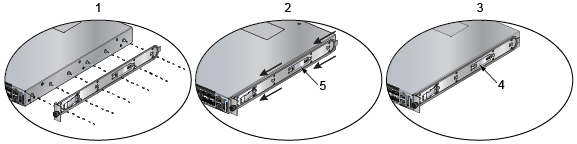
| 1 | Step 1 | 2 | Step 2 | 3 | Step 3 |
| 4 | Bracket clip (attached) | 5 | Bracket clip (aligned) |
This procedure attaches the rails to a four-post rack:
The rail clip prevents the extension of the rail beyond the maximum supported distance between the front and rear rack posts.
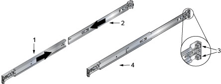
| 1 | Rail-slide | 3 | Rack plugs |
| 2 | Rail-rod | 4 | Rail (assembled) |
| 1 | Inset A | 2 | Inset B |
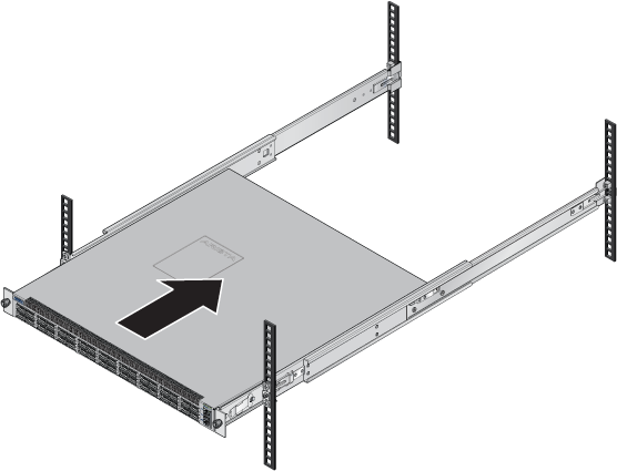
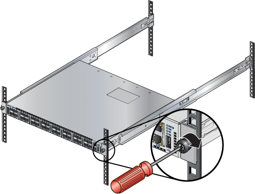
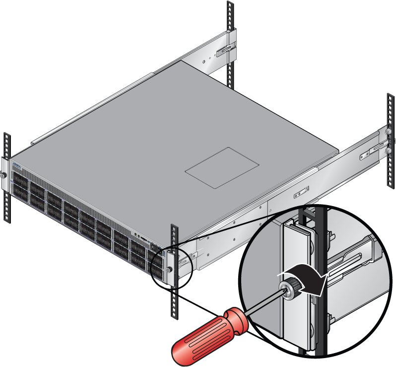
After installing the rails, the switch slides on the rails into the rack. Each bracket includes a thumb screw that attaches the switch to the rail.
After completing the four-post rack mount, proceed to Cabling the Switch.
This section discusses the following topics:
The rack mounting procedure is identical for all switches this guide covers. Illustrations in this section depict the mounting of a DCS-7050SX-128 switch.
Les procédure de montage du bâti est identique pour tous les commutateurs visés par ce guide. Illustrations dans ce chapitre montrent le montage d'un interrupteur de DCS-7050SX-128.
After completing the instructions for your rack type, proceed to Cabling the Switch.
The 2RU switches covered in this guide do not support two-post rack mounting. The accessory kit contains only the four-post RMK components. Contact your local Arista Networks representative for further information if you require two-post rack mounting.
The switch mounts onto a four-post rack by assembling two rails onto the rear posts, sliding the switch onto the rails, and securing the switch to the front posts.
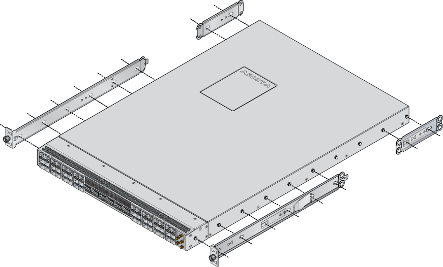
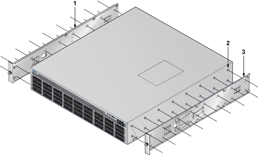
Each chassis side has attachment pins that align with bracket holes; the number of pins (six or seven) varies by switch model. Pin orientation is symmetric and central, with supporting bracket placement where the flange is either flush with the front and rear panels or not flush with the panels. Each bracket hole includes a key opening for placing the bracket flush with the chassis and then locking it into place.
Attachment pins must engage all six bracket holes.
Goupilles de fixation doivent s’engager tous les trous de support six.
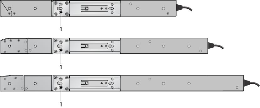
The following figure displays a bracket-rail assembly and the components (bracket and rail) extracted from the assembly kit. Each assembly must be separated into components before mounting the switch into a four-post rack. The two assemblies supplied with the switch are identical.
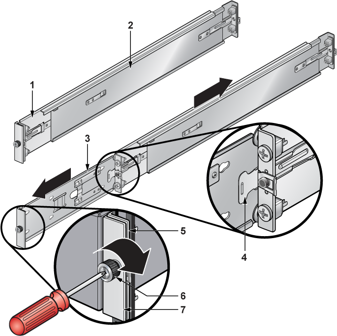
| 1 | Rail bracket (front) | 2 | Rail bracket (rear) | 3 | Switch bracket (for attaching to switch) |
| 4 | Locking clip | 5 | Rail mounting ear | 6 | Thumb screw |
| 7 | Switch mounting ear |
This procedure separates a bracket-rail assembly into its component pieces.
| 1 | Switch bracket | 2 | Attach point | 3 | Matching attachment hole |
This procedure attaches mounting brackets to the switch chassis as depicted by the following figure.
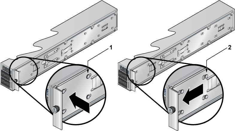
| 1 | Aligned rail | 2 | Seated rail |
To remove the mounting bracket from the chassis, lift the front edge of the mounting bracket clip with a flathead screwdriver and slide the bracket away from the front flange (opposite from the installation direction).
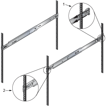
The rail is initially contracted and must be expanded to attach to the rack. This procedure expands the rails from their contracted state:
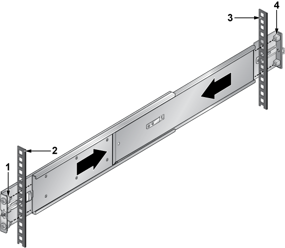
| 1 | Front of right rail | 3 | Right rack post (rear) |
| 2 | Right rack post (front) | 4 | Rear of right rail |
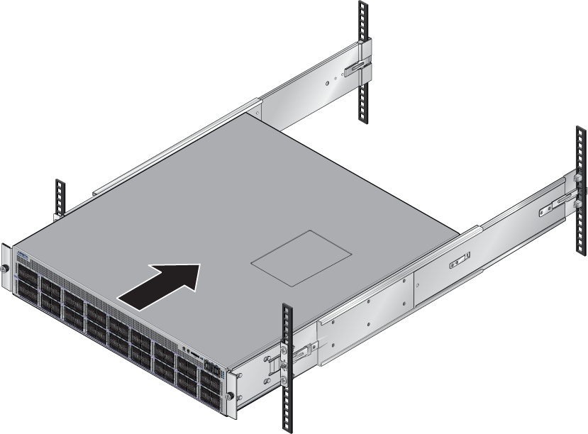
After completing the four-post rack mount, proceed to Cabling the Switch.
