Rack Mounting the Switch
This section discusses the following topics:
DCS-7804, DCS-7808, DCS-7812, DCS-7816, and DCS-7816L Rack Mounting
The accessory kit provides components for installing the switch in four-post racks. The accessory kit includes the following four-post mounting parts:
- Cradle assembly
- M6 pan-head Phillips screws
- M6 rack cage nuts (optional)
- Template for non-threaded racks requiring rack nuts
Note: Two-post rack mount is not supported.
Illustrations in this chapter depict the mounting of an unpopulated 8-slot chassis.
After completing the instructions for your rack type, proceed to Cabling the Power Supplies.
Perform the following tasks to mount the switch in a four-post rack:
- Insert rack nuts (for racks requiring them) at appropriate locations. (Inserting Rack Nuts Using the Template).
- Insert and secure the cradle assembly into the rack (Inserting and Securing the Cradle Assembly).
- Insert the switch into the rack (Inserting the Switch into the Rack).
Inserting Rack Nuts Using the Template
Note: Required only for non-threaded racks that use rack nuts. Installation is referenced with the bottom screw located at the 1RU location. For a different starting point for the bottom screw, always start at an RU location, and ensure there is enough room for your device in the rack.
- Insert rack-mount cage nuts required by the switch (Table 1) at the locations identified by the Figure 1 using the template.
Note: The number of cage rack nuts required for the front left and front right rack posts is different. The rear posts require the same number (4 each).Note: If the system includes the four rack nuts, distinct from the others as shown in the following figure, place them in the lowest positions on both the front and rear rack rails. The locations are indicated by an orange highlight and a star.
Figure 1. Cage Rack Nut Locations 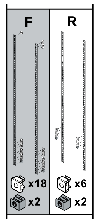
1 Mounting location A Front (Left and Right) 4 Mounting location D Front (Left and Right) 2 Mounting location B Front (Left and Right) 5 Mounting location Rear (Left and Right) 3 Mounting location C Front (Left and Right) The following figure shows the rack mount locations for the switches.Figure 2. Rack Mount Locations 
Table 1. Rack Mount Locations and Screws Required by Switch Mounting Location1 DCS-7804 DCS 7808 DCS-7812 DCS-7816 Front (L) Front (R) Front (L) Front (R) Front (L) Front (R) Front (L) Front (R) A 5 5 5 5 5 5 5 5 B N/A N/A N/A N/A 3 3 4 4 C N/A N/A N/A N/A N/A N/A 2 3 D 1 2 1 2 1 2 2 2 1. Rear post locations are indicated by the template and are used for securing the cradle.
Inserting and Securing the Cradle Assembly
Note: The rack mounting cradle is shipped nested upside down over the top of the chassis for all switches. A protective film on the top and sides prevents the cradle from scratching the chassis during transport.
- Insert two screws loosely in the two front rack posts at the same level and two in the back two rack posts 3 RU above the front screws (Figure 3). Use the template for racks requiring rack nuts (Figure 4). The front locations are marked with single dots, and the rear locations with two dots.
Figure 3. Attaching Mounting Screws to the Rack Posts 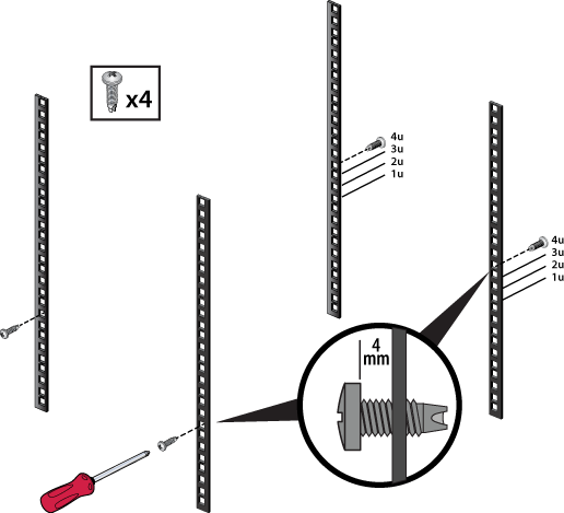
Figure 4. Mounting (Starting Screws) Locations for Cradle (Front and Rear) 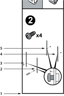
1 Bottom of switch 4 Rear Screw (Left) 2 Front screw (Right) 5 Rear Screw (Right) 3 Front Screw (Left) - Prior to installation, buckle the straps on the cradle together so the left and right sides are angled slightly inwards.
Figure 5. Buckling the Straps 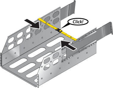
- Slide the rear sliding rails back in so that they are flush with the back rack posts, the notches in the cradle engage behind the loosely mounted screws, and the bottom of the cradle is horizontal and level.
Figure 6. Inserting the Cradle 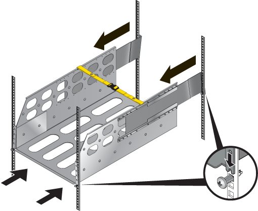
- Release the clasp on the connector to rotate the left and right sides so they are vertical.
Figure 7. Aligning the Cradle in the Rack 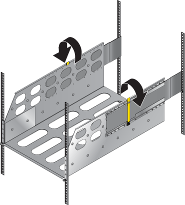
- Secure the cradle to the rack posts using the eight remaining screws, two more in the front and six more in the back, for a total of twelve screws.
Figure 8. Securing the Cradle in the Rack 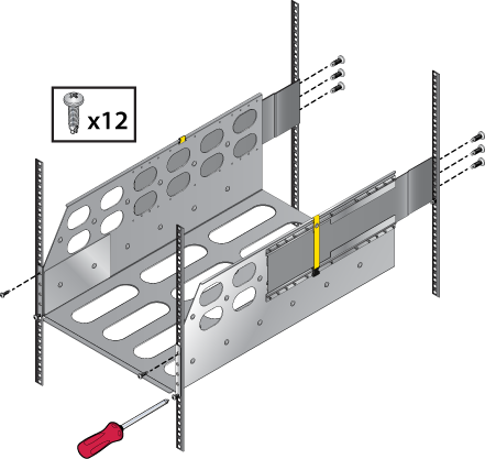
Inserting the Switch into the Rack
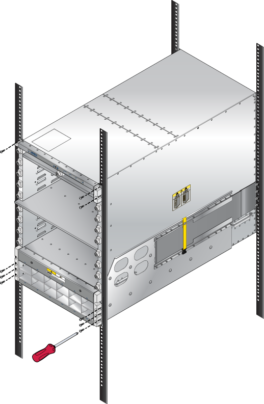
- Lift the chassis and insert it into the rack. For the DCS-7816 chassis, remove the lifting brackets from the top of the chassis, which are required to lift the chassis from the pallet onto a transport lift before insertion.
Note: A platform lift is recommended for transportation and installation.
Figure 9. Lifting the Chassis 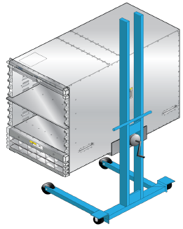
- Secure the chassis by tightening additional M6 screws on the front flanges into the rack posts.
Note: Additional screws depend on the device. The 7804 and 7808 chassis require nine.
Figure 10. Secure the Switch to the Rack Shelf