
VeloCloud Orchestrator Deployment and Monitoring Guide
The VeloCloud SD-WAN Orchestrator Deployment and Monitoring Guide provides guidance on how to install, run, and monitor the Orchestrator.
This topic contains the following sections:
Overview
The VeloCloud SD-WAN Orchestrator Deployment and Monitoring Guide provides guidance on installing, running, and monitoring the Edge Cloud Orchestrator.
- Installing the Orchestrator
- Setting Up Disaster Recovery
- Upgrading the Orchestrator
- Backing Up the Orchestrator Application Data
- Monitoring the Orchestrator application
- Tuning various system properties (depending on the scale of the deployment)
Installing Orchestrator
This topic discusses the Orchestrator installation and it contains the following sections:
Prerequisites
This topic discusses the prerequisites for installing Orchestrator,and it contains the following sections:
Instance Requirements
Arista recommends installing the Orchestrator and Gateway applications as virtual machines, for example, as guest instances, on an existing hypervisor.
- 8 Intel vCPU's at 2.5 GHz or higher
Note: Arista recommends using Intel Xeon processors; similar Intel or AMD processors with the same or greater CPU frequency are also acceptable.
- 64 GB of memory
- Required Minimum IOPS: 5,000 IOPS
- Orchestrator requires 4 SSD-based persistent volumes, expandable through LVM if necessary.
- 192GB x 1- Root
- 1TB x 1- Store
- 500GB x 1- Store2
- 1TB x 1- Store3
- 1 Gbps NIC
- Ubuntu x64 server VM compatibility
- Single public IP address made available through NAT
Upstream Firewall Configuration
The upstream firewall must to be configured to allow inbound HTTP (TCP/80) and HTTPS (TCP/443). If a stateful firewall is in place, established outbound connections should also be allowed to facilitate upgrades and security updates.
External Services
The Orchestrator relies on several external services. Before proceeding with an installation, ensure you have available licenses for each service.
Google Maps
Google Maps displays Edges and data centers on a map and does not require a Google account to use the functionality.However, the Orchestrator instance must have Internet access for the service to be available.
The service is limited to 25,000 map loads each day for more than 90 consecutive days. VeloCloud does not anticipate exceeding these limits for nominal Orchestrator use. For additional information, see Configure System Properties for Google Maps.
Twilio
VeloCloud uses Twilio for SMS-based alerting to enterprise customers and notifies them of Edge or link outage events. An account needs to be created and funded at http://www.twilio.com.
The account can be provisioned in the Orchestrator through the Operator Portals System Properties page. The account provisions are through a system property, as described later in the guide. See Configure System Properties for Twilio for additional information.
MaxMind
MaxMind provides geolocation services and automatically detects Edge and Gateway locations and ISP names based on IP address. If this service deactivates, you must manually update the geolocation information. The account can be provisioned in the Orchestrator through the Operator Portal's System Properties page. See Configure System Properties for MaxMind for additional information.
Installation Procedures
This topic discusses installation, and it contains the following sections:
Preparing the Cloud-init
This section discusses how to use the cloud-init package to perform early instance initialization.
About cloud-init
cloud-initis a Linux package that handles the early initialization of instances. If available in the distributions, it allows configuration of many common instance parameters directly after installation. This creates a fully functional instance with a configuration based on a series of inputs.
cloud-init behavior can be configured with user data. Provide the user data at instance launch time and attach a secondary disk in ISO format that cloud-init searches for at first boot.This disk contains all the early configuration data to apply at that time.
The Orchestrator supports cloud-init and all essential configurations packaged in an ISO image.
Creating the Cloud-init Metadata File
The final installation configuration options are set with a pair of cloud-init configuration files. The first installation configuration file contains the metadata. Create this file with a text editor and label it metadata. This file provides information that identifies the instance of Orchestrator to be installed. The instance-id can be any identifying name, and the local-hostname should be a host name that follows your site standards, for example:
instance-id: vco01
local-hostname: vco-01
Additionally, you can specify network interface information if the network does not have a DHCP configuration, for example:
instance-id: vco01
local-hostname: vco-01
network-interfaces: |
  auto eth0
  iface eth0 inet static
  address 10.0.1.2
  network 10.0.1.0
  netmask 255.255.255.0
  broadcast 10.0.1.255
  gateway 10.0.1.1
Create the Cloud-init User-data File
The second installation configuration option file contains the user data. This file provides information about users on the system. Create it with a text editor and name it user-data. This file enables access to the installation of Orchestrator. The following provides an example of the user-data file:
#cloud-config
password: Velocloud123
chpasswd: {expire: False}
ssh_pwauth: True
ssh_authorized_keys:
- ssh-rsa AAA...SDvz This email address is being protected from spambots. You need JavaScript enabled to view it.
- ssh-rsa AAB...QTuo This email address is being protected from spambots. You need JavaScript enabled to view it.
vco:
super_users:
list: |
This email address is being protected from spambots. You need JavaScript enabled to view it.:password1
remove_default_users: True
system_properties:
list: |
mail.smtp.port:34
mail.smtp.host:smtp.yourdomain.com
service.maxmind.enable:True
service.maxmind.license:todo_license
service.maxmind.userid:todo_user
service.twilio.phoneNumber:222123123
network.public.address:222123123
write_files:
- path: /etc/nginx/velocloud/ssl/server.crt
permissions: '0644'
content: "-----BEGIN CERTIFICATE-----\nMI….ow==\n-----END CERTIFICATE-----\n"
- path: /etc/nginx/velocloud/ssl/server.key
permissions: '0600'
content: "-----BEGIN RSA PRIVATE KEY-----\nMII...D/JQ==\n-----END RSA PRIVATE KEY-----\n"
- path: /etc/nginx/velocloud/ssl/velocloudCA.crt
chpasswd lines.
- The password contains the plain-text password for the vcadmin user.
- The
chpasswdline turns off password expiration to prevent the first login from immediately prompting for a change of password. This is optional.
The ssh_pwauth line enables SSH login. The ssh_authorized_keys line begins a block of one or more authorized keys. Each public SSH key listed on the ssh-rsa lines will be added to the vcadmin ~/.ssh/authorized_keys file.
In this example, two keys are listed. For this example, the key has been truncated. In a real file, the entire public key must be listed. Note that the ssh-rsa lines must be preceded by two spaces, followed by a hyphen, followed by another space.
The vco section specifies configured Orchestrator services.
Super_users contains a list of VeloCloud Super Operator accounts and corresponding passwords.
The system_properties section allows to customize Orchestrator System Properties. See System Properties for details regarding system properties configuration.
server.crt and server.key files in the /etc/nginx/velocloud/ssl/ folder with user-supplied files.
server.key file must be unencrypted. Otherwise, the service fails to start without the key password.Create an ISO File
Once you have completed your files, package them into an ISO image. Use the ISO image as a virtual configuration CD with the virtual machine. This ISO image, called vco01-cidata.iso, was created with the following command on a Linux system:
genisoimage -output vco01-cidata.iso -volid cidata -joliet -rock user-data meta-data
Transfer the newly created ISO image to the datastore on the host running VeloCloud.
Install on vSphere
Deploy OVA Template
Attach an ISO Image as a CD/DVD to a Virtual Machine
- Right-click the newly-added Orchestrator VM and select Edit Settings.
- From the Virtual Machine Properties window, select CD/DVD Drive.
- Select the Use an ISO image option.
- Browse to find the ISO image you created earlier and then select it. The ISO can be found in the datastore that you uploaded it to, in the folder that you created.
- Select Connect on Power On.
- Select OK to exit the Properties screen.
Run the Orchestrator Virtual Machine
Install on KVM
This section explains how to run the Orchestrator using libvirt. This deployment was tested on an Ubuntu 18.04 LTS instance.
Images
qcow images.
ROOTFSSTORESTORE2STORE3
The images thin provision on deployment.
Start by copying the images to the KVM server. In addition, you must copy the cloud-init ISO build as described in the previous section.
XML Sample
<domain type='kvm' id='49'>
  <name>vco</name>
  <uuid>b0ff25bc-72b8-6ccb-e777-fdc0f4733e05</uuid>
  <memory unit='KiB'>12388608</memory>
  <currentMemory unit='KiB'>12388608</currentMemory>
  <vcpu>2</vcpu>
  <resource>
    <partition>/machine</partition>
  </resource>
  <os>
  <type>hvm</type>
  </os>
  <features>
    <acpi/>
    <apic/>
    <pae/>
  </features>
    <cpu mode='custom' match='exact'>
    <model fallback='allow'>SandyBridge</model>
    <vendor>Intel</vendor>
    <feature policy='require' name='vme'/>
    <feature policy='require' name='dtes64'/>
    <feature policy='require' name='invpcid'/>
    <feature policy='require' name='vmx'/>
    <feature policy='require' name='erms'/>
    <feature policy='require' name='xtpr'/>
    <feature policy='require' name='smep'/>
    <feature policy='require' name='pbe'/>
    <feature policy='require' name='est'/>
    <feature policy='require' name='monitor'/>
    <feature policy='require' name='smx'/>
    <feature policy='require' name='abm'/>
    <feature policy='require' name='tm'/>
    <feature policy='require' name='acpi'/>
    <feature policy='require' name='fma'/>
    <feature policy='require' name='osxsave'/>
    <feature policy='require' name='ht'/>
    <feature policy='require' name='dca'/>
    <feature policy='require' name='pdcm'/>
    <feature policy='require' name='pdpe1gb'/>
    <feature policy='require' name='fsgsbase'/>
    <feature policy='require' name='f16c'/>
    <feature policy='require' name='ds'/>
    <feature policy='require' name='tm2'/>
    <feature policy='require' name='avx2'/>
    <feature policy='require' name='ss'/>
    <feature policy='require' name='bmi1'/>
    <feature policy='require' name='bmi2'/>
    <feature policy='require' name='pcid'/>
    <feature policy='require' name='ds_cpl'/>
    <feature policy='require' name='movbe'/>
    <feature policy='require' name='rdrand'/>
  </cpu>
<clock offset='utc'/>
  <on_poweroff>destroy</on_poweroff>
  <on_reboot>restart</on_reboot>
  <on_crash>restart</on_crash>
  <devices>
    <emulator>/usr/bin/kvm-spice</emulator>
    <disk type='file' device='disk'>
      <driver name='qemu' type='qcow2'/>
      <source file='/images/vco/rootfs.qcow2'/>
      <target dev='hda' bus='ide'/>
      <alias name='ide0-0-0'/>
      <address type='drive' controller='0' bus='0' target='0' unit='0'/>
    </disk>
    <disk type='file' device='disk'>
      <driver name='qemu' type='qcow2'/>
      <source file='/ images/vco/store.qcow2'/>
      <target dev='hdb' bus='ide'/>
      <alias name='ide0-0-1'/>
      <address type='drive' controller='0' bus='0' target='0' unit='1'/>
    </disk>
    <disk type='file' device='disk'>
      <driver name='qemu' type='qcow2'/>
      <source file='/ images/vco/store2.qcow2'/>
      <target dev='hdc' bus='ide'/>
      <alias name='ide0-0-2'/>
      <address type='drive' controller='0' bus='1' target='0' unit='0'/>
    </disk>
    <disk type='file' device='disk'>
      <driver name='qemu' type='qcow2' />
      <source file='/images/vco/store3.qcow2' />
      <target dev='hdd' bus='ide' />
      <alias name='ide0-0-3' />
      <address type='drive' controller='0' bus='1' target='0' unit='1' />
    </disk>
    <disk type='file' device='cdrom'>
      <driver name='qemu' type='raw'/>
      <source file='/ images/vco/seed.iso'/>
      <target dev='sdb' bus='sata'/>
      <readonly/>
      <alias name='sata1-0-0'/>
      <address type='drive' controller='1' bus='0' target='0' unit='0'/>
    </disk>
    <controller type='usb' index='0'>
      <alias name='usb0'/>
      <address type='pci' domain='0x0000' bus='0x00' slot='0x01' function='0x2'/>
    </controller>
    <controller type='pci' index='0' model='pci-root'>
      <alias name='pci.0'/>
    </controller>
    <controller type='ide' index='0'>
      <alias name='ide0'/>
      <address type='pci' domain='0x0000' bus='0x00' slot='0x01' function='0x1'/>
    </controller>
    <interface type='direct'>
      <source dev='eth0' mode='vepa'/>
    </interface>
    <serial type='pty'>
      <source path='/dev/pts/3'/>
      <target port='0'/>
      <alias name='serial0'/>
    </serial>
    <console type='pty' tty='/dev/pts/3'>
      <source path='/dev/pts/3'/>
      <target type='serial' port='0'/>
      <alias name='serial0'/>
    </console>
    <memballoon model='virtio'>
      <alias name='balloon0'/>
      <address type='pci' domain='0x0000' bus='0x00' slot='0x03' function='0x0'/>
    </memballoon>
  </devices>
  <seclabel type='none' />
<!--  <seclabel type='dynamic' model='apparmor' relabel='yes'/> -->
</domain>
Create the VM
To create the VM using the standard virsh commands:
virsh define vco.xml
virsh start vco.xml
Install on AWS
This section discusses how to install Orchestrator on AWS.
Minimum Instance Requirements
See the first section of the Orchestrator Installation, Instance Requirements, and select an AWS instance type matching these requirements. Both CPU and Memory requirements must be satisfied. Example: use c4.2xlarge or larger; r4.2xlarge or larger
Request an AMI Image
Request an AMI ID from VeloCoud. It will be shared with the customer account. Have an Amazon AWS account ID ready when requesting AMI access.
Installation
- Launch the EC2 instance in the AWS cloud.
Example:http://docs.aws.amazon.com/efs/latest/ug/gs-step-one-create-ec2-resources.html
- Configure the security group to allow inbound HTTP (TCP/80) and HTTPS (TCP/443).
- After the instance is launched, point the web browser to the Operator login URL: https://<name>/operator.
Initial Configuration Tasks
This topic contains the following sections:
- Configuring system properties
- Setting up initial operator profile
- Setting up operator accounts
- Creating gateways
- Setting up gateway pools
- Creating a customer account/partner account
Install an SSL Certificate
This section discusses how to install an SSL certificate.
To install an SSL certificate:
Log in to the Orchestrator CLI console via SSH. If you configured the Orchestrator as described here, you should be able to log in to the virtual machine with the username vcadmin and the password you defined when you created the cloud-init ISO.
Configure System Properties
Set the System Properties initially by using the cloud-init config file. For additional information, see Preparing the Cloud-init. Configure the following properties to ensure proper service operation.
System Name
network.public.address system property.Google Maps
- Login into https://console.developers.google.com.
- Create a new project if one does not already exist.
- Locate the button Enable API. Select the Google Maps APIs and enable both Google Maps JavaScript API and Google Maps Geolocation API.
- On the left side of the screen, select the Credentials link.
- Under the Credentials page, select Create Credentials, then select API key. Create an API key.
- Set the
service.client.googleMapsApi.keysystem property to API key. - Set
service.client.googleMapsApi.enabletotrue.
Twilio
Twilio provides an optional messaging service that allows you to receive VeloCloud alerts via SMS. You can enter the account details into VeloCloud through the Operator Portal System Properties page. The properties are called:
service.twilio.enableallows the service to be deactivated if no Internet access is available.service.twilio.accountSidservice.twilio.authTokenservice.twilio.phoneNumberin (nnn)nnn-nnnn format.
Obtain the service at https://www.twilio.com.
MaxMind
MaxMind is a geolocation service. It automatically detects Edge and Gateway locations and ISP names from an IP address. If this service is deactivated, then geolocation information will need to be updated manually. You can enter the account details through the Operator Portal's System Properties page. You can configure:
service.maxmind.enableallows the service to be deactivated if no Internet access is available.service.maxmind.useridholds the user identification supplied by MaxMind during the account creation.service.maxmind.licenseholds the license key supplied by MaxMind.
Obtain the license at: https://www.maxmind.com/en/geoip-api-web-services.
mail.smtp.auth.pass- SMTP user password.mail.smtp.auth.user- SMTP user for authentication.mail.smtp.host- relay server for email originated from the VeloCloud.mail.smtp.port- SMTP port.mail.smtp.secureConnection- use SSL for SMTP traffic.
Upgrading Orchestrator
To upgrade the Orchestrator:
Expanding Disk Size
To expand disks after boot:
System Properties
In the Operator portal, navigate to the System Properties page, which lists the available pre-defined system properties. See List of System Properties, which lists some of the system properties that you can modify as an Operator.
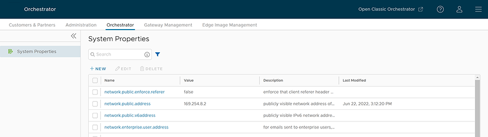
To configure the system properties:
- In the New System Property window, configure the following parameters:
Figure 2. Add a New System Property 
Table 3. New System Property Option Descriptions Option Description Name Enter the Name for the new system property. Data Type Choose the required Data Type from the drop-down menu. Value Enter the Value for the property according to the data type. Value is Password Select Yes or No as required. Value is Read-only Select Yes or No for as required. Description Enter the Description for the new system property
List of System Properties
As an Operator, you can add or modify the values of the system properties.
- Alert Emails
- Alerts
- Bastion Orchestrator Configuration
- Certificate Authority
- Customer Configuration
- Data Retention
- Edges
- Edge Activation
- Edge Management
- Enhanced Firewall Services
- LAN-Side NAT Rules
- Link Insights
- Monitoring
- Multi-scope access for VeloBrain
- Notifications
- Password Reset and Lockout
- Rate Limiting APIs
- Remote Diagnostics
- Security Service Edge
- Segmentation
- Self-service Password Reset
- Syslog Forwarding
- TACACS Services
- Two-factor Authentication
- Time-Based One Time Passcode (TOTP)
- Tunnel Parameters for Edges
- VNF Configuration
- VPN
- Warning Banner
- Zscaler
| System Property | Description |
|---|---|
vco.alert.mail.to |
When an alert is triggered, a notification is sent immediately to the list of Email addresses provided in the Value field of this system property. You can enter multiple Email IDs separated by commas.
If the property does not contain any value, then the notification is not sent. The notification is meant to alert Arista support / operations personnel of impending issues before notifying the customer. |
vco.alert.mail.cc |
When alert emails are sent to any customer, a copy is sent to the Email addresses provided in the Value field of this system property. You can enter multiple Email IDs separated by commas. |
mail.* |
There are multiple system properties available to control the Alert Emails. You can define the Email parameters like SMTP properties, username, password, and so on. |
| System Property | Description |
|---|---|
vco.alert.enable |
Globally activates or deactivates the generation of alerts for both Operators and Enterprise customers. |
vco.enterprise.alert.enable |
Globally activates or deactivates the generation of alerts for Enterprise customers. |
vco.operator.alert.enable |
Globally activates or deactivates the generation of alerts for Operators. |
| System Property | Description |
|---|---|
session.options.enableBastionOrchestrator |
Enables the Bastion Orchestrator feature.
For additional information, see Bastion Orchestrator Configuration Guide. |
vco.bastion.private.enable |
Enables the Orchestrator to be the Private Orchestrator of the Bastion pair. |
vco.bastion.public.enable |
Enables the Orchestrator to be the Public Orchestrator of the Bastion pair. |
| System Property | Description |
|---|---|
edge.certificate.renewal.window |
This optional system property allows the Operator to define one or more maintenance windows during which the Edge certificate renewal is enabled. Certificates scheduled for renewal outside of the windows will be deferred until the current time falls within one of the enabled windows.
Enable System Property: To enable this system property, type "true" for "enabled" in the first part of the Value text area in the Modify System Property dialog box. An example of the first part of this system property when it is enabled is shown below. Operators can define multiple windows to restrict the days and hours of the day during which Edge renewals are enabled. Each window can be defined by a day, or a list of days (separated by a comma), and a start and end time. Start and end times can be specified relative to an Edge's local time zone, or relative to UTC. See image below for an example.  Note: If attributes are not present, the default is false.
When defining window attributes, adhere to the following:
If the above-mentioned values are missing, the attribute defaults in each window definition are as follow:
Deactivate System Property This system property is deactivated by default, which means the certificate will automatically renew after it expires. "Enabled" will be set to "false in the first part of the Value text area in the Modify System Property dialog box. An example of this property when it is deactivated is shown below. {
"enabled": false,
"windows": [
{
Note: This system property requires that PKI be enabled.
|
gateway.certificate.renewal.window |
This optional system property allows the Operator to define one or more maintenance windows during which the Gateway certificate renewal is enabled. Certificates scheduled for renewal outside of the windows will be deferred until the current time falls within one of the enabled windows.
Enable System Property: To enable this system property, type "true" for "enabled" in the first part of the Value text area in the Modify System Property dialog box. See image below for an example. Operators can define multiple windows to restrict the days and hours of the day during which edge renewals are enabled. Each window can be defined by a day, or list of days (separated by a comma), and a start and end time. Start and end times can be specified relative to an edge's local timezone, or relative to UTC. See image below for an example.  Note: If attributes are not present, the default is enabled
false.When defining window attributes, adhere to the following:
If the above-mentioned values are missing, the attribute defaults in each window definition are as follow:
Deactivate System Property This system property is deactivated by default, which means the certificate will automatically renew after it expires. "Enabled" will be set to "false in the first part of the Value text area in the Modify System Property dialog box. An example of this property when it is deactivated is shown below. {
"enabled": false,
"windows": [
{
Note: This system property requires that PKI be enabled.
|
| System Property | Description |
|---|---|
session.options.enableServiceLicenses |
This system property allows Operator users to manage Service Configuration under , and is set to True, by default. |
| System Property | Description |
|---|---|
retention.highResFlows.days |
This system property enables Operators to configure high resolution flow stats data retention anywhere between 1 and 90 days. |
retention.lowResFlows.months |
This system property enables Operators to configure low resolution flow stats data retention anywhere between 1 and 365 days. |
session.options.maxFlowstatsRetentionDays |
This property enables Operators to query more than two weeks of flows stats data. |
retentionWeeks.enterpriseEvents |
Enterprise events retention period (-1 sets retention to the maximum time period allowed) |
retentionWeeks.operatorEvents |
Operator events retention period (-1 sets retention to the maximum time period allowed) |
retentionWeeks.proxyEvents |
Proxy events retention period (-1 sets retention to the maximum time period allowed) |
retentionWeeks.firewallLogs |
Firewall logs retention period (-1 sets retention to the maximum time period allowed) |
retention.linkstats.days |
Link stats retention period (-1 sets retention to the maximum time period allowed) |
retention.linkquality.days |
Link quality events retention period (-1 sets retention to the maximum time period allowed) |
retention.healthstats.days |
Edge health stats retention period (-1 sets retention to the maximum time period allowed) |
retention.pathstats.days |
Path stats retention period (-1 sets retention to the maximum time period allowed) |
| SD-WAN Data | Date Retention Period |
|---|---|
| Enterprise Events | 1 year |
| Enterprise Alerts | 1 year |
| Operator Events | 1 year |
| Enterprise Proxy Events | 1 year |
| Link Stats | 1 year |
| Link QoE | 1 year |
| Path Stats | 2 weeks |
| Flow Stats (Low Resolution) | 1 year – 1 hour rollup |
| Flow Stats (High Resolution) | 2 weeks – 5 minute rollup |
| Edge Health Stats | 1 year |
| System Property | Description |
|---|---|
edge.offline.limit.sec |
If the Orchestrator does not detect a heartbeat from an Edge for the specified duration, then the state of the Edge is moved to OFFLINE mode. |
edge.link.unstable.limit.sec |
When the Orchestrator does not receive link statistics for a link for the specified duration, the link is moved to UNSTABLE mode. |
edge.link.disconnected.limit.sec |
When the Orchestrator does not receive link statistics for a link for the specified duration, the link is disconnected. |
edge.deadbeat.limit.days |
If an Edge is not active for the specified number of days, then the Edge is not considered for generating Alerts. |
vco.operator.alert.edgeLinkEvent.enable |
Globally activates or deactivates Operator Alerts for Edge Link events. |
vco.operator.alert.edgeLiveness.enable |
Globally activates or deactivates Operator Alerts for Edge Liveness events. |
| System Property | Description |
|---|---|
edge.activation.key.encode.enable |
Base64 encodes the activation URL parameters to obscure values when the Edge Activation Email is sent to the Site Contact. |
edge.activation.trustedIssuerReset.enable |
Resets the trusted certificate issuer list of the Edge to contain only the Orchestrator Certificate Authority. All TLS traffic from the edge are restricted by the new issuer list. |
network.public.certificate.issuer |
Set the value of network.public.certificate.issuer equal to the PEM encoding of the issuer of Orchestrator server certificate, when edge.activation.trustedIssuerReset.enable is set to True. This will add the server certificate issuer to the trusted issuer of the Edge, in addition to the Orchestrator Certificate Authority. |
| System Property | Description |
|---|---|
edge.link.show.limit.sec |
Allows to set the Edge Link Down Limit value for each Edge. |
session.options.enableKafkaFwStatsIngestion |
Enables seamless ingestion of firewall statistics through Kafka. If this system property is disabled, the system automatically defaults to a two-stage MySQL process for ingesting firewall statistics, as was done in earlier versions. |
ntics.public
address |
Specifies the hostname that is used to access the NSX Threat Intelligent Cloud Service (NTICS). |
firewall.monitorNTICSLicenseExpiry.invocation.interval |
Specifies the number of seconds between checking NSX Threat Intelligent Cloud Service (NTICS) expiry. |
ntics.register.path |
Specifies the registration path used to access the NSX Threat Intelligent Cloud Service (NTICS). |
gsm.public.address |
Specifies the Public address of Global Services Manager (GSM). |
gsm.authentication.key |
Specifies the mTLS key to authenticate with GSM. |
gsm.authentication.cert |
Specifies the mTLS certificate to authenticate with GSM. |
gsm.authentication.passphrase |
Specifies the mTLS passphrase to authenticate with GSM. |
firewall.pollIdpsSignatureV2FromGSM.enabled |
Enables the job to poll ATP Signature V2 from GSM. |
firewall.pollIdpsSignatureFromGSM.invocation.interval |
Specifies the number of seconds between polling GSM for the ATP signature file. |
firewall.pollIdpsSignatureFromGSM.maxSignatureFilesToRetain |
Specifies the maximum number of ATP signature files to store. |
firewall.pollUrlFilteringCategoriesFromGSM.enabled |
Enables the job to poll URL categories from GSM. |
firewall.pollUrlFilteringCategoriesFromGSM.invocation.interval |
Specifies the number of seconds between polling GSM for URL categories. |
storage.idps.signature.file.location |
Specifies a valid directory for the file system storage location for IDPS Signature files. |
| System Property | Description |
|---|---|
session.options.enableLansidePortRules |
Allows to configure the parameters Inside Port and Outside Port under for an Edge or Profile. |
| System Property | Description |
|---|---|
enterprise.capability.enableLinkinsights |
Enables the Link Insights capability for Enterprise customers. |
session.options.enableLinkinsights |
Enables the Link Insights feature in the user session. |
| System Property | Description |
|---|---|
vco.monitor.enable |
Globally activates or deactivates monitoring of Enterprise and Operator entity states. Setting the value to False prevents Orchestrator from changing entity states and triggering alerts. |
vco.enterprise.monitor.enable |
Globally activates or deactivates monitoring of Enterprise entity states. |
vco.operator.monitor.enable |
Globally activates or deactivates monitoring of Operator entity states. |
| System Property | Description |
|---|---|
sessions.options.enableVeloAI |
Set the value to True to activate VeloBrain for Operators. |
vco.system.configuration.data.veloAiNginxRedirectionUrl |
Set the value appropriately to enable VeloBrain configuration in the Orchestrator. |
| System Property | Description |
|---|---|
edge.liveData.enterFlowLiveMode.delay.seconds |
How long the Edge waits before giving up on capturing the count configured by edge.liveData.enterFlowLiveMode.delay.seconds. The default value is five seconds. The allowed range is 5- 59 seconds. The invalid input defaults to zero seconds. |
edge.liveData.enterFlowLiveMode.flow.count |
How many flows the Edge will return if met within the configured time controlled by edge.liveData.enterFlowLiveMode.flow.count. The default value is 1000. The allowed range is 1000- 4999 total flows. The invalid input defaults to one flow. |
| System Property | Description |
|---|---|
vco.notification.enable |
Globally activates or deactivates the delivery of Alert notifications to both Operator and Enterprises. |
vco.enterprise.notification.enable |
Globally activates or deactivates the delivery of Alert notifications to the Enterprises. |
vco.operator.notification.enable |
Globally activates or deactivates the delivery of Alert notifications to the Operator. |
| System Property | Description |
|---|---|
vco.object.groups.max.count.per.enterprise |
Maximum allowed number of object groups per Enterprise. The default value is 2000. |
vco.object.groups.max.count.per.edge |
Maximum allowed number of object group associations per Edge and its Profile. The default value is 1000. |
| System Property | Description |
|---|---|
vco.enterprise.resetPassword.token.expirySeconds |
Duration of time, after which the password reset link for an enterprise user expires. |
vco.enterprise.authentication.passwordPolicy |
Defines the password strength, history, and expiration policy for customer users.
Edit the JSON template in the Value field to define the following: strength:
Since the new password only varies by 3 characters from the old, “sitting” would be rejected as a new password to replace “kitten”. The default value of-1 signifies that this feature is not enabled. expiry:
history:
|
enterprise.user.lockout.defaultAttempts |
Number of times the enterprise user can attempt to login. If the login fails for the specified number of times, the account is locked. |
enterprise.user.lockout.defaultDurationSeconds |
Duration of time, in seconds, in which the Enterprise user account is locked.
For example, if set to 300, the Enterprise user account will get locked if four incorrect login attempts are made within 300 seconds. If set to 60, the Enterprise user account will get locked if four incorrect attempts are made within one minute. Note: The number of attempts is configurable via the
enterprise.user.lockout.defaultAttempts system property. |
enterprise.user.lockout.enabled |
Activates or deactivates the lockout option for the enterprise login failures. |
vco.operator.resetPassword.token.expirySeconds |
Duration of time, after which the password reset link for an Operator user expires. |
vco.operator.authentication.passwordPolicy |
Defines the password strength, history, and expiration policy for Operator users.
Edit the JSON template in the Value field to define the following: strength:
Since the new password only varies by 3 characters from the old, “sitting” would be rejected as a new password to replace “kitten”. The default value of-1 signifies that this feature is not enabled. expiry::
history:
|
operator.user.lockout.defaultAttempts |
Number of times the Operator user can attempt to login. If the login fails for the specified number of times, the account is locked. |
operator.user.lockout.defaultDurationSeconds |
Duration of time, in seconds, in which an Operator user account is locked.
For example, if set to 300, the Operator user account will get locked if four incorrect login attempts are made within 300 seconds. If set to 60, the Operator user account will get locked if four incorrect attempts are made within one minute. Note: The number of attempts is configurable via the
operator.user.lockout.defaultAttempts system property. |
operator.user.lockout.enabled |
Activates or deactivates the lockout option for the Operator login failures. |
| System Property | Description |
|---|---|
vco.api.rateLimit.enabled |
Allows Operator Super users activate or deactivate the rate limiting feature at the system level. By default, the value is False.
Note: The rate-limiter is not enabled in earnest, that is, it will not reject API requests that exceed the configured limits, unless the
vco.api.rateLimit.mode.logOnly setting is deactivated. |
vco.api.rateLimit.mode.logOnly |
Allows Operator Super user to use rate limit in a LOG_ONLY mode. When the value is set as True and if a rate limit exceeds, this option logs only the error and fires respective metrics allowing clients to make requests without rate limiting.
When the value is set to False, the request API is restricted with defined policies and HTTP 429 is returned. |
vco.api.rateLimit.rules.global |
Allows to define a set of globally applicable policies used by the rate-limiter, in a JSON array. By default, the value is an empty array.
Each type of user (Operator, Partner, and Customer) can make up to 500 requests for every 5 seconds. The number of requests is subject to change based on the behavior pattern of the rate limited requests. The JSON array consists of the following parameters: Types: The type objects represent different contexts in which the rate limits are applied. The following are the different type objects that are available:
Policies: Add rules to the policies to apply the requests that match the rule, by configuring the following parameters:
Enabled: Each type limit can be activated or deactivated by including the enabled key in APIRateLimiterTypeObject. By default, the value of enabled is True, even if the key is not included. You need to include key to deactivate the individual type limits. The following example shows a sample JSON file with default values: [ { "type": "OPERATOR_USER", "policies": [ { "match": { "type": "ALL" }, "rules": { "reservoir": 500, "reservoirRefreshAmount": 500, "reservoirRefreshInterval": 5000 } } ] }, { "type": "MSP_USER", "policies": [ { "match": { "type": "ALL" }, "rules": { "reservoir": 500, "reservoirRefreshAmount": 500, "reservoirRefreshInterval": 5000 } } ] }, { "type": "ENTERPRISE_USER", "policies": [ { "match": { "type": "ALL" }, "rules": { "reservoir": 500, "reservoirRefreshAmount": 500, "reservoirRefreshInterval": 5000 } } ] } ]
Note: It is recommended not to change the default values of the configuration parameters.
|
vco.api.rateLimit.rules.enterprise.default |
Comprises the default set of Enterprise-specific policies applied to newly created Customers. The Customer-specific properties are stored in the Enterprise property vco.api.rateLimit.rules.enterprise. |
vco.api.rateLimit.rules.enterpriseProxy.default |
Comprises the default set of Enterprise-specific policies applied to newly created Partners. The Partner-specific properties are stored in the Enterprise proxy property vco.api.rateLimit.rules.enterpriseProxy. |
| System Property | Description |
|---|---|
network.public.address |
Specifies the browser origin address/DNS hostname that is used to access the Orchestrator UI. |
network.portal.websocket.address |
Allows to set an alternate DNS hostname/address to access the Orchestrator UI from a browser, if the browser address is not the same as the value of network.public.address system property.
As remote diagnostics now uses a WebSocket connection, to ensure web security, the browser origin address that is used to access the Orchestrator UI is validated for incoming requests. In most cases, this address is same as the network.public.address system property. In rare scenarios, the Orchestrator UI can be accessed using another DNS hostname/address that is different from the value set in the network.public.address system property. In such cases, you can set this system property to the alternate DNS hostname/address. By default, this value is not set. |
session.options.websocket.portal.idle.timeout |
Allows to set the total amount of time (in seconds) the browser WebSocket connection is active in an idle state. By default, the browser WebSocket connection is active for 300 seconds in an idle state. |
| System Property | Description |
|---|---|
session.options.enableSseService |
Activates or deactivates the Security Service Edge (SSE) feature for Enterprise users. |
| System Property | Description |
|---|---|
enterprise.capability.enableSegmentation |
Activates or deactivates the segmentation capability for Enterprise users. |
enterprise.segments.system.maximum |
Specifies the maximum number of segments allowed for any Enterprise user. Ensure that you change the value of this system property to 128 if you want to enable 128 segments on Orchestrator for an Enterprise user. |
enterprise.segments.maximum |
Specifies the default value for the maximum number of segments allowed for a new or existing Enterprise user. The default value for any Enterprise user is 16.
Note: This value must be less than or equal to the number defined in the system property, enterprise.segments.system.maximum.
It is not recommended for you to change the value of this system property if you want to enable 128 segments for an Enterprise user. Instead, you can enable Customer Capabilities in the Customer Configuration page to configure the required number of segments. |
enterprise.subinterfaces.maximum |
Specifies the maximum number of sub-interfaces that can be configured for an Enterprise user. The default value is 32. |
enterprise.vlans.maximum |
Specifies the maximum number of VLANs that can be configured for an Enterprise user. The default value is 32. |
session.options.enableAsyncAPI |
When the segment scale is increased to 128 segments for any Enterprise user, to prevent UI timeouts, you can enable Async APIs support on the UI by using this system property. The default value is true. |
session.options.asyncPollingMilliSeconds |
Specifies the Polling interval for Async APIs on the UI. The default value is 5000 milliseconds. |
session.options.asyncPollingMaxCount |
Specifies the maximum number of calls to get Status API from the UI. The default value is 10. |
vco.enterprise.events.configuration.diff.enable |
Activates or deactivates configuration diff event logging. Whenever the number of segments for an Enterprise user is greater than 4, the configuration diff event logging will be deactivated. You can enable configuration diff event logging using this system property. |
| System Property | Description |
|---|---|
vco.enterprise.resetPassword.twoFactor.mode |
Defines the mode for the second level for password reset authentication, for all the Enterprise users. Currently, only the SMS mode is supported. |
vco.enterprise.resetPassword.twoFactor.required |
Activates or deactivates the two-factor authentication for password reset of Enterprise users. |
vco.enterprise.selfResetPassword.enabled |
Activates or deactivates self-service password reset for Enterprise users. |
vco.enterprise.selfResetPassword.token.expirySeconds |
Duration of time, after which the self-service password reset link for an Enterprise user expires. |
vco.operator.resetPassword.twoFactor.required |
Activates or deactivates the two-factor authentication for password reset of Operator users. |
vco.operator.selfResetPassword.enabled |
Activates or deactivates self-service password reset for Operator users. |
vco.operator.selfResetPassword.token.expirySeconds |
Duration of time, after which the self-service password reset link for an Operator user expires. |
| System Property | Description |
|---|---|
log.syslog.backend |
Backend service syslog integration configuration. |
log.syslog.portal |
Portal service syslog integration configuration. |
log.syslog.upload |
Upload service syslog integration configuration. |
log.syslog.lastFetchedCRL.backend |
Keeps the last updated CRL as PEM formatted string for service syslog and updated regularly. |
log.syslog.lastFetchedCRL.portal |
Keeps the last updated CRL as PEM formatted string for service syslog and updated regularly. |
log.syslog.lastFetchedCRL.upload |
Keeps the last updated CRL as PEM formatted string for service syslog and updated regularly. |
| System Property | Description |
|---|---|
session.options.enableTACACS |
Activates or deactivates the TACACS services for Enterprise users. |
| System Property | Description |
|---|---|
vco.enterprise.authentication.twoFactor.enable |
Activates or deactivates the two-factor authentication for Enterprise users. |
vco.enterprise.authentication.twoFactor.mode |
Defines the mode for the second level authentication for Enterprise users. Currently, only SMS is supported as the second level authentication mode. |
vco.enterprise.authentication.twoFactor.require |
Defines the two-factor authentication as mandatory for Enterprise users. |
vco.operator.authentication.twoFactor.enable |
Activates or deactivates the two-factor authentication for Operator users. |
vco.operator.authentication.twoFactor.mode |
Defines the mode for the second level authentication for Operator users. Currently, only SMS is supported as the second level authentication mode. |
vco.operator.authentication.twoFactor.require |
Defines the two-factor authentication as mandatory for Operator users. |
| System Property | Description |
|---|---|
vco.enterpriseProxy.authentication.twoFactor.mode |
Supports modes for Two Factor Authentication. The default mode is TOTP. |
| System Property | Description |
|---|---|
session.options.enableNsdPkiIPv6Config |
Activates Certificate Authentication mode and IPv6 Local Identification Type. |
| System Property | Description |
|---|---|
edge.vnf.extraImageInfos |
Defines the properties of a VNF Image.
You can enter the following information for a VNF Image, in JSON format in the Value field:
[ { "vendor": " Vendor Name", "version": " VNF Image Version", "checksum": " VNF Checksum Value", "checksumType": " VNF Checksum Type" } ]
Example of JSON file for Check Point Firewall Image:
[ { "vendor": "checkPoint", "version": "r80.40_no_workaround_46", "checksum": "bc9b06376cdbf210cad8202d728f1602b79cfd7d", "checksumType": "sha-1" } ]
Example os JSON file for Fortinet Firewall Image:
[ { "vendor": "fortinet", "version": "624", "checksum": "6d9e2939b8a4a02de499528c745d76bf75f9821f", "checksumType": "sha-1" } ]
|
edge.vnf.metric.record.limit |
Defines the number of records to be stored in the database. |
enterprise.capability.edgeVnfs.enable |
Allows VNF deployment on supported Edge models. |
enterprise.capability.edgeVnfs.securityVnf.checkPoint |
Activates Check Point Networks Firewall VNF. |
enterprise.capability.edgeVnfs.securityVnf.fortinet |
Activates Fortinet Networks Firewall VNF. |
enterprise.capability.edgeVnfs.securityVnf.paloAlto |
Activates Palo Alto Networks Firewall VNF. |
session.options.enableVnf |
Activates VNF feature. |
vco.operator.alert.edgeVnfEvent.enable |
Activates or deactivates Operator alerts for Edge VNF events globally. |
vco.operator.alert.edgeVnfInsertionEvent.enable |
Activates or deactivates Operator alerts for Edge VNF Insertion events globally. |
edge.vnf.extraImageInfos. |
Allows selection of the Check Point VNF image. |
| System Property | Description |
|---|---|
vpn.disconnect.wait.sec |
The time interval for the system to wait before disconnecting a VPN tunnel. |
vpn.reconnect.wait.sec |
The time interval for the system to wait before reconnecting a VPN tunnel. |
| System Property | Description |
|---|---|
login.warning.banner.message |
This optional system property allows the Operator to configure and display a Security Administrator-specified advisory notice and consent warning message regarding the use of Orchestrator. The warning message is displayed in the Orchestrator prior to user login.
For instructions about how to configure this system property, see the topic Configure Advisory Notice and Consent Warning Message for SD-WAN Orchestrator. |
| System Property | Description |
|---|---|
session.options.enableZscalerProfileAutomation |
Enables to configure Zscaler settings at the Profile level. |
Configure Orchestrator Disaster Recovery
This section provides disaster recovery (DR) instructions for Orchestrator, and it contains the following sections:
Orchestrator Disaster Recovery Overview
The Orchestrator Disaster Recovery (DR) feature prevents data loss and resumes Orchestrator services in the event of system or network failure.
- The Recovery Time Objective (RTO), therefore, depends on the operator explicitly triggering the promotion of the standby.
- The Recovery Point Objective (RPO), however, is essentially zero regardless of the recovery time, because all configuration replicates instantaneously. Monitoring data collected during the outage is cached on the Edges and Gateways until the standby promotion.
Active/Standby Pair
In an Orchestrator DR deployment, you can configure two identical Orchestrator systems as an active/standby pair. The operator can view the DR readiness status in the web UI on either server. Edges and Gateways are aware of both Orchestrators. While they receive configuration changes only from the active Orchestrator, they periodically send DR heartbeats to both systems to report their view of both servers and to query the DR system status. When the operator triggers a failover, it informs the Edges and Gateways of the change in their next DR heartbeat.
DR States
From the view of an operator, and of the edges and gateways, a Orchestrator has one of four DR states:
| DR State | Description |
|---|---|
| Standalone | No DR configured. |
| Active | DR configured, acting as the primary Orchestrator server. |
| Standby | DR configured, acting as an inactive replica Orchestrator server. |
| Zombie | DR formerly configured and active, but no longer acting as the active or standby. |
Run-time Operation
After configuring DR, the standby server runs in a limited mode, blocking all API calls except those related to the DR status and the DR heartbeats. When the operator initiates a failover, the system promotes the standby to full operational status as a Standalone server. The server that was formerly active is automatically transitioned to a Zombie state if it is responsive and visible from the promoted standby. In the Zombie state, management configuration services are blocked, and any contact from Edges and Gateways that have not transitioned to the new active Orchestrator is redirected to the promoted server.

Set Up Orchestrator Replication
- The selected standby is put into a
STANDBY_CANDIDATEstate, enabling it to be configured by the active server. - The active server has the standby's address and credentials, and it enters the
ACTIVE_CONFIGURINGstate.
When you create a STANDBY_CONFIG_RQST from Active to Standby, the two servers synchronize through the state transitions.
- The Gateway time zone must be set to Etc/UTC. Use the following command to view the NTP time zone.
vcadmin@vcg1-example:~$ cat /etc/timezone
Etc/UTC
vcadmin@vcg1-example:~$
If the time zone is incorrect, use the following commands to update it.
echo "Etc/UTC" | sudo tee /etc/timezone
sudo dpkg-reconfigure --frontend noninteractive tzdata
- The NTP offset must be less than or equal to 15 milliseconds. Use the following command to view the NTP offset.
sudo ntpqvcadmin@vcg1-example:~$ sudo ntpq -p
     remote           refid      st t when poll reach   delay   offset  jitter
==============================================================================
*ntp1-us1.prod.v 74.120.81.219    3 u  474 1024  377   10.171   -1.183   1.033
 ntp1-eu1-old.pr .INIT.          16 u    - 1024    0    0.000    0.000   0.000
vcadmin@vcg1-example:~$
If the offset is incorrect, use the following commands to update it.
sudo systemctl stop ntp
sudo ntpdate <server>
sudo systemctl start ntp
- By default, the system configures a list of NTP Servers in the
/etc/ntpd.conffile. The Orchestrators where you intend to establish Disaster Recovery (DR) must have Internet access to reach the default NTP Servers and ensure the system synchronizes the time on both Orchestrators. Alternatively, customers can use a local NTP server running in their own environment to synchronize the time.
network.public.address system property.Set Up the Standby Orchestrator
- Select Replication from the Navigation panel to display the Orchestrator Replication screen.
Figure 6. Orchestrator Replication 
- Enable the Standby Orchestrator by selecting Standby (Replication Role).
Figure 7. Enable Standby Orchestrator Replication Role 
- Select Enable for Standby. The Prepare this Orchestrator for Standby Role dialog displays.
Figure 8. Enable for Standby 
- Select OK.
Figure 9. Configure Standby Orchestrator 
After configuring the Standby Orchestrator for replication, configure the Active Orchestrator.
Set Up the Active Orchestrator
- Type in the Standby Orchestrator Address and the Standby Orchestrator UUID. The Orchestrator Address and UUID display in the Standby Orchestrator screen.
Figure 10. Set Up Active Orchestrator Replication 
- Select Make Active. The Active Orchestrator screen displays showing a status of the current state.
Figure 11. Configure Active Orchestrator Replication Settings 
When configuration is complete, both Orchestrators (Standby and Active) will be in sync.
Standby Orchestrator in Sync

You can select the toggle history link to view the status of each state.
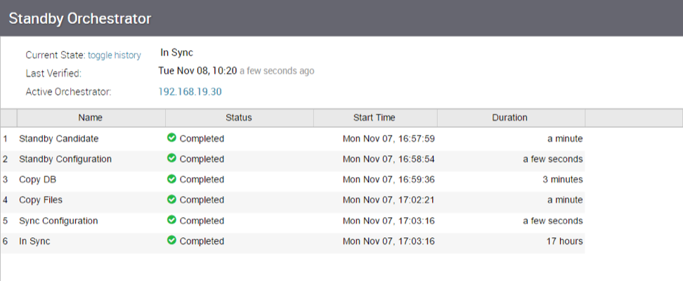
Active Orchestrator in Sync

Test Failover
This topic contains the following sections:
The following testing failover scenarios are forced failovers for example purposes. You can perform these actions in the Available Actions area of the Active and Standby screens.
Promote a Standby Orchestrator
To promote a Standby Orchestrator
- Select the Promote Standby button in the Available Actions area on the Standby Orchestrator screen.
Figure 15. Available Actions 
The following dialog box appears, indicating that when you promote your Standby Orchestrator, administrators will no longer be able to manage the Orchestrator using the previously Active Orchestrator.
Figure 16. Promote a Standby Orchestrator 
- Select OK to promote the Orchestrator.
Figure 17. Promote to Standby Confirmation Dialog 
A final dialog box appears indicating that the Orchestrator is no longer a Standby and will restart in Standalone mode.
Figure 18. Remove Standby Orchestrator Confirmation Dialog 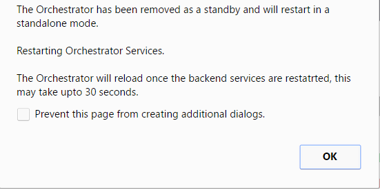
When you promote a Standby Orchestrator, it restarts in Standalone mode.
If the Standby can communicate with the formerly Active Orchestrator, it instructs the Orchestrator to enter a Zombie state. In Zombie state, the Orchestrator communicates with its clients (edges, gateways, UI/API) that it is no longer active, and that they must communicate with the newly promoted Orchestrator. If the promoted Standby cannot communicate with the formerly Active Orchestrator, the operator should, if possible, manually demote the formerly Active Orchestrator.
Figure 19. Quiesced Orchestrator 
Return to Standalone Mode
To return the Zombie to standalone mode, select Return to Standalone Mode in the Available Actions area on the Active Orchestrator or Standby Orchestrator screens.

vco.disasterRecovery.zombie.expirySeconds system property expires. By default, the system sets this duration to 1800 seconds.Troubleshoot Orchestrator DR
This section describes the system's failure states. The Orchestrator UI also lists these states and provides a detailed description of each failure. You can find additional troubleshooting information in the VeloCloud log.
Recoverable Failures
FAILURE_SYNCING_FILESFAILURE_GET_STANDBY_STATUSFAILURE_MYSQL_ACTIVE_STATUSFAILURE_MYSQL_STANDBY_STATUS
Unrecoverable Failures
FAILURE_ACTIVE_CONFIGURINGFAILURE_LAUNCHING_STANDBYFAILURE_STANDBY_CONFIGURINGFAILURE_COPYING_DBFAILURE_COPYING_FILESFAILURE_SYNC_CONFIGURINGFAILURE_GET_STANDBY_CONFIGFAILURE_STANDBY_CANDIDATEFAILURE_STANDBY_UNCONFIGFAILURE_STANDBY_PROMOTIONFAILURE_ACTIVE_DEMOTION
Replication
The Orchestrator Disaster Recovery (DR) feature prevents data loss and resumes Orchestrator services during a system or network failure.
Orchestrator DR involves setting up an active/standby Orchestrator pair using data replication and a manually-triggered failover mechanism. Consequently, the Recovery Time Objective (RTO) depends on the operator taking explicit action to promote the standby unit.
The Recovery Point Objective (RPO) remains essentially zero regardless of recovery time, because the system instantaneously replicates all configurations. Edges and Gateways cache any monitoring data collected during the outage until you promote the standby Orchestrator.
Active/Standby Pair
In an Orchestrator DR deployment, the administrator configures two identical Orchestrator systems as an active/standby pair. The operator can view the DR readiness state through the Web UI on either server.
Both Edges and Gateways recognize both Orchestrators. While they receive configuration changes only from the active Orchestrator, they periodically send DR heartbeats to both systems. These heartbeats allow the Edges and Gateways to report their status and query the current DR system status. When the operator triggers a failover, the system informs the Edges and Gateways of the change during their next scheduled heartbeat.
DR States
From the perspective of the operator, the Edges, and the Gateways, an Orchestrator exists in one of the following four DR states:
| DR State | Description |
|---|---|
| Standalone | No DR configured. |
| Active | DR configured, acting as the primary Orchestrator server. |
| Standby | DR configured, acting as an inactive replica Orchestrator server. |
| Zombie | DR formerly configured and active but no longer acting as the active or standby. |
Run-time Operation
When you configure DR, the standby server runs in a limited mode. In this mode, the system blocks all API calls except those related to DR status and DR heartbeats.
When the operator invokes a failover, the system promotes the standby to a fully operational Standalone server. If the formerly active server remains responsive and visible to the promoted standby, the system automatically transitions it to a Zombie state.
In the Zombie state, the server blocks management configuration services. If any Edges or Gateways attempt to contact the Zombie server before transitioning to the new active Orchestrator, the Zombie server redirects them to the promoted server.

Set Up Orchestrator Replication
- The selected standby is put into a
STANDBY_CANDIDATEstate, enabling it to be configured by the active server. - The active server has the standby's address and credentials, and it enters the
ACTIVE_CONFIGURINGstate.
When you create a STANDBY_CONFIG_RQST from Active to Standby, the two servers synchronize through the state transitions.
- The Gateway time zone must be set to Etc/UTC. Use the following command to view the NTP time zone.
vcadmin@vcg1-example:~$ cat /etc/timezone
Etc/UTC
vcadmin@vcg1-example:~$
If the time zone is incorrect, use the following commands to update the time zone.
echo "Etc/UTC" | sudo tee /etc/timezone
sudo dpkg-reconfigure --frontend noninteractive tzdata
- The NTP offset must be less than or equal to 15 milliseconds. Use the following command to view the NTP offset.
sudo ntpqvcadmin@vcg1-example:~$ sudo ntpq -p
     remote           refid      st t when poll reach   delay   offset  jitter
==============================================================================
*ntp1-us1.prod.v 74.120.81.219    3 u  474 1024  377   10.171   -1.183   1.033
 ntp1-eu1-old.pr .INIT.          16 u    - 1024    0    0.000    0.000   0.000
vcadmin@vcg1-example:~$
If the offset is incorrect, use the following commands to update the NTP offset.
sudo systemctl stop ntp
sudo ntpdate <server>
sudo systemctl start ntp
- By default, the system configures a list of NTP Servers in the
/etc/ntpd.conffile. The Orchestrators where you intend to establish Disaster Recovery (DR) must have Internet access to reach the default NTP Servers and ensure the system synchronizes the time on both Orchestrators. Alternatively, customers can use a local NTP server running in their own environment to synchronize the time.
Set Up the Standby Orchestrator
- In the SD-WAN service of the Enterprise portal, select the Orchestrator tab then from the left pane select Replication button to display the Orchestrator Replication screen.
- Activate the Standby Orchestrator by selecting the Standby (Replication Role) radio button
- Select the Enable for Standby button.
Figure 22. Set Up Standby Orchestrator Replication 
The Standby Orchestrator page appears.
- Enter the manual configuration parameters and select Update configuration info button.
After you configure the Standby Orchestrator for replication, configure the Active Orchestrator by following the instructions below.
Set Up the Active Orchestrator
To set up the Active Orchestrator, select the Replication Role as Active and configure the following:

| Option | Description |
|---|---|
| Select Replication Role | Select the Active radio button for the replication role. |
| Standby Orchestrator Address | Enter the primary Standby Orchestrator IP Address. |
| Standby Orchestrator Address (IPv6) | Enter the Standby Orchestrator IPv6 Address. |
| Standby Orchestrator Secondary Address | Enter the address of the standby Orchestrator's secondary interface. The system uses this address for replication if you promote the standby Orchestrator to active status. Users can add an IPv4 address, IPv6 address, or FQDN in this field. |
| Standby Orchestrator UUID | Enter the UUID of the standby Orchestrator. |
| Configuration Mode | Select the Auto Configure Standby or Manually Configure Standby radio button based on the requirement.
When configured manually, paste a string value from ACTIVE VCO to STANDBY_WAIT. |
| Superuser Username | Enter the display name for the Orchestrator Superuser. |
| Standby Orchestrator Superuser Password | Enter the password for the Orchestrator Superuser.
Note: Starting with Release 4.5, the system no longer supports the use of the special character
< in passwords. If users previously included < in their passwords in earlier releases, they must remove it before the system will allow them to save any changes on the page. |
- Select Enable for Active button to activate replication role.
When configuration is complete, both Orchestrators (Standby and Active) are in sync.
Standby Orchestrator in Sync
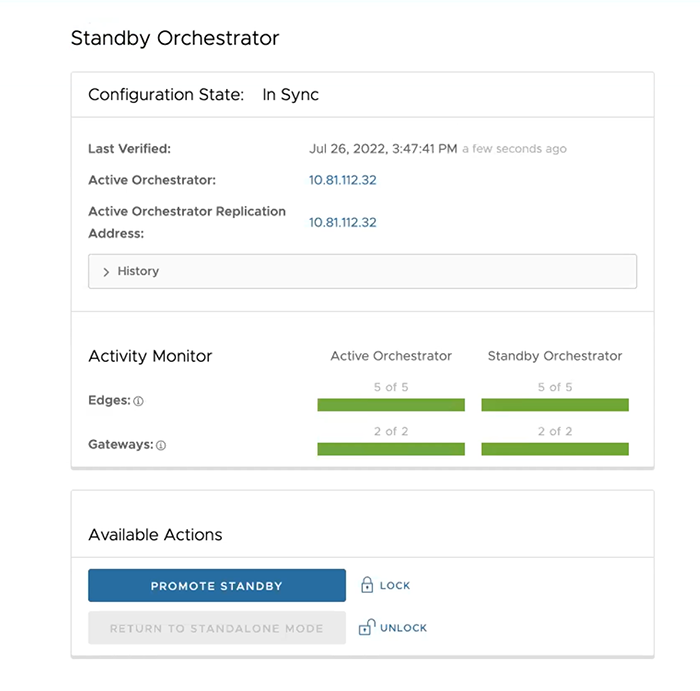
Active Orchestrator in Sync

Test Failover
The following testing failover scenarios are forced failovers for example purposes. You can perform these actions in the Available Actions area of the Active and Standby screens.
Promote a Standby Orchestrator
This section discusses how to promote a Standby Orchestrator.
- Select the unlock link.
- Select the Promote Standby button in the Available Actions area on the Standby Orchestrator screen.
Figure 26. Available Actions 
The following dialog box appears, indicating that when you promote your Standby Orchestrator, administrators can no longer be able to manage the Orchestrator using the previously Active Orchestrator.
Figure 27. Promote Orchestrator to Standby 
- Select the Promote Standby button to promote the Standby Orchestrator.
- Select Force Promote Standby to promote the Orchestrator.
Figure 28. Force Promote Standby 
A final dialog box appears indicating that the Orchestrator is no longer a Standby and restarts in Standalone mode.
Figure 29. Restart in Standalone Mode Notice 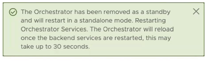
When you promote a Standby Orchestrator, it restarts in Standalone mode.
If the Standby can communicate with the formerly Active Orchestrator, it instructs that Orchestrator to enter a Zombie state. In Zombie state, the Orchestrator communicates with its clients (edges, gateways, UI/API) that it is no longer active, and that they must communicate with the newly promoted Orchestrator. If the promoted Standby cannot communicate with the formerly Active Orchestrator, the operator should, if possible, manually demote the formerly Active Orchestrator.

Return to Standalone Mode
To return the Zombie to standalone mode, select the Return to Standalone Mode button in the Available Actions area on the Active Orchestrator or Standby Orchestrator screens.

Troubleshooting Orchestrator DR
This section describes the system's failure states. The Orchestrator UI also lists these states and provides a detailed description of each failure. You can find additional troubleshooting information in the Arista log.
Recoverable Failures
- FAILURE_SYNCING_FILES
- FAILURE_GET_STANDBY_STATUS
- FAILURE_MYSQL_ACTIVE_STATUS
- FAILURE_MYSQL_STANDBY_STATUS
Unrecoverable Failures
- FAILURE_ACTIVE_CONFIGURING
- FAILURE_LAUNCHING_STANDBY
- FAILURE_STANDBY_CONFIGURING
- FAILURE_COPYING_DB
- FAILURE_COPYING_FILES
- FAILURE_SYNC_CONFIGURING
- FAILURE_GET_STANDBY_CONFIG
- FAILURE_STANDBY_CANDIDATE
- FAILURE_STANDBY_UNCONFIG
- FAILURE_STANDBY_PROMOTION
- FAILURE_ACTIVE_DEMOTION
Upgrade Orchestrator
This section discusses how to upgrade the Orchestrator, and it contains the following sections:
Orchestrator Upgrade Overview
- Prepare for the Orchestrator Upgrade.
- Send Upgrade Announcement.
- Proceed with the Orchestrator upgrade.
- Complete the Orchestrator Upgrade.
Upgrade an Orchestrator
This section discusses how to upgrade an Orchestrator, and it contains the following sections:
Step 1: Prepare for the Orchestrator Upgrade
To prepare for your Orchestrator upgrade, contact the Arista Support team.
Steps to Upgrade the Orchestrator:
- Current and Target Versions: Specify both the current version (e.g., 2.5.2 GA-20180430) and your desired target version (e.g., 3.3.2 p2).
Note: To find the current version, click the Help link in the top-right corner of the Orchestrator and select About.
- Replication Dashboard Screenshot: Provide a screenshot of the Orchestrator's replication dashboard to verify current system health.
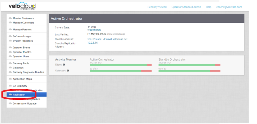
- Hypervisor Type and version (i.e. vSphere 6.7)
- Commands from the Orchestrator:
Note: Commands must be run as root (e.g. sudo <command> or sudo-i).
- Run the script /opt/vc/scripts/vco_upgrade_check.sh to check:
- LVM layout
- Memory Information
- CPU Information
- Kernel Parameters
- Some system properties
- ssh configurations
- Mysql schema and database sizes
- File_store locations and sizes
- Copy of
/var/logtar -czf /store/log-`date +%Y%M%S`.tar.gz --newer-mtime="36 hours ago" /var/log
- From the Standby Orchestrator:
sudo mysql
--defaults-extra-file=/etc/mysql/velocloud.cnf
velocloud -e 'SHOW SLAVE STATUS \G'
- Run the script /opt/vc/scripts/vco_upgrade_check.sh to check:
- From the Active Orchestrator:
sudo mysql --defaults-extra-file=/etc/mysql/velocloud.cnf
velocloud -e 'SHOW MASTER STATUS \G'
Step 2: Send Upgrade Announcement
- In the Upgrade Announcement area, type in your message in the Banner Message text box.
Figure 33. Configure the Upgrade Announcement 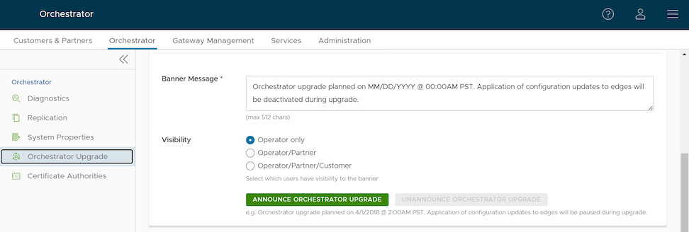
- Select Announce Orchestrator Upgrade. A pop-up message appears indicating successful creation of your announcement and your banner message displays at the top of the Orchestrator.
Figure 34. Remove the Upgrade Announcement 
(Optional) You can remove the announcement from the Orchestrator by selecting Unannounce Orchestrator Upgrade. A message appears indicating you successfully unannounced the Orchestrator upgrade. The announcement displayed at the top of the Orchestrator disappears.
Step 3- Before Proceeding with the Orchestrator Upgrade
This section provides essential details for the administrator to consider before upgrading the Orchestrator, along with an explanation of the image-based upgrade process. You must contact Arista Support to assist you with the transition from Release 5.4 to Release 6.0.
Consider the Following When Upgrading to the 6.0 Release
- This upgrade work does not modify any existing APIs.
- Just like other releases, there are schema changes with the 6.0 release. However, these changes will not impact the upgrade process.
- The OS version is changing from Ubuntu 18.04 to 22.04.
- Image based upgrade instead of a Debian based upgrade.
Important Notes for Upgrading from 5.4 to 6.0
- Any non-supported binaries installed on top of Orchestrator will be removed. These can include the off-the-shelf monitoring applications, remote access applications, etc.
- Back up any configurations if you want to continue using them. After the upgrade, you must reinstall them manually and configure them accordingly.
- The upgrade process requires a mandatory system-level REBOOT of the Orchestrator.
- After a successful upgrade, the Orchestrator does not support rolling back to the previous release. Therefore, ensure you have backups of the entire system, including /store, /store2, /store3, and so forth, before upgrading.
- At least 30GB of free space is required on the physical disk before upgrading the Orchestrator from 5.4.0 to 6.0.0.
Image-based Upgrade Process
- An Ubuntu 22.04-based VCO image is prepared with all required binaries with LVM partitions / and /var/.
- The / and /var/ LVM partitions are "snapshotted" to represent new image rooftfs.
- The system packages these snapshots with upgrade scripts to serve two primary functions:
- The scripts transfer specific configurations—notably those associated with MySQL, Nginx, SSH, and their respective keys—from the existing system to the new snapshots.
- The scripts adjust the boot configuration to ensure the system boots using the new LVM partitions, completing the upgrade process.
- The image-based upgrade replaces the old file system with a new one. As noted, this process may result in the loss of unsupported files and packages. The administrator should contact Arista Support before the upgrade to ensure a safe and successful transition.
Best Practices/Recommendations:
- Leave the demoted Orchestrator up for a few hours before complete shutdown or decommission.
- Freeze configuration modifications to avoid any additional configuration changes until the upgrade process is completed.
Step 4: Proceed with the Orchestrator Upgrade
Contact Arista Support at for assistance with the Orchestrator upgrade.
Step 5: Complete the Orchestrator Upgrade
When you complete the Orchestrator upgrade, select Complete Orchestrator Upgrade. This re-enables the application of the configuration updates of Edges at the global level.
dpkg -l|grep vcoAs an Operator, the same version number should display at the bottom right corner of the Orchestrator.
Orchestrator Disaster Recovery
This topic discusses how to set up and upgrade disaster recovery in the Orchestrator:
Set Up DR in the VeloCloud
- Install a new Orchestrator whose version matches the version of the VeloCloud that is currently the Active Orchestrator.
- Set the following properties on the Active and Standby Orchestrator, if necessary:
- Set
vco.disasterRecovery.transientErrorToleranceSecsto a non-zero value (it defaults to 900 seconds in version 3.3 and later, but to zero in earlier versions). This prevents any transient errors from resulting in an Edge/Gateway management plane update. - Set
vco.disasterRecovery.mysqlExpireLogsDays(defaults is 1 day). This is the amount of time the Active Orchestrator keeps themysql binlogdata.
- Set
- Set up the
network.public.addressproperty on the Active and Standby Orchestrators to the address contacted by the Edges (Heartbeats). - Set up DR by following the usual DR Setup procedure that is described in Orchestrator Disaster Recovery.
Upgrade the DR Setup
- Prepare for the upgrade. For instructions, go to Step 1: Prepare for the Orchestrator Upgrade of the section titled, Upgrade an Orchestrator with DR Deployment.
- Proceed with the Orchestrator upgrade. For instructions, go to Step 4: Proceed with the Orchestrator Upgrade of the section titled, Upgrade an Orchestrator with DR Deployment.
Troubleshoot Orchestrator
This topic discusses Orchestrator troubleshooting, and it contains the following sections:
Orchestrator Diagnostics Overview
The Orchestrator Diagnostics bundle is a collection of diagnostic information required by Support and Engineering to troubleshoot Orchestrator. For Orchestrator on-premises installation, Operators can collect the Orchestrator Diagnostic bundle from the Orchestrator UI and provide it to the Arista Support team for offline analysis and troubleshooting.
- Diagnostic Bundles Tab: Request and download a diagnostic bundle. This information can be found in the Arista SD-WAN Orchestrator Deployment and Monitoring Guide. See the section titled, Diagnostic Bundle Tab.
- Database Statistics Tab: Provides read-only access to some information from a diagnostic bundle. This information can be found in the Arista SD-WAN Orchestrator Deployment and Monitoring Guide. See the section titled, Database Statistics Tab.
Diagnostics Bundle Tab
Users can request and download a diagnostic bundle in the Diagnostics Bundle tab.
Columns in the Diagnostics Bundle Tab
The Orchestrator Diagnostics table grid includes the following columns:
| Column Name | Description |
|---|---|
| Request Status | There are two types of status requests:
|
| Reason for Generation | The specific reason given for generating a diagnostic bundle. Select the Request Diagnostic Bundle button to include a description of the bundle. |
| User | The individual logged into the Orchestrator. |
| Generated | The date and time when the diagnostic bundle request was sent. |
| Cleanup Date | The default Cleanup Date is three months after the generated date, when the bundle will be automatically deleted. If you need to extend the Cleanup date period, select the Cleanup Date link located under the Cleanup Date column. For additional information, see Updating Cleanup Date. |
Request a Diagnostic Bundle
- From the Orchestrator navigation panel, select Diagnostics.
Figure 35. Orchestrator Diagnostics Screen 
- In the Request Diagnostic Bundle dialog, enter the reason for the request in the appropriate area.
Figure 36. Request Diagnostic Bundle 
Download a Diagnostic Bundle
- Select a diagnostic bundle you want to download.
- Select the Actions button, and choose Download Diagnostic Bundle. You can also select the Complete link to download the diagnostics bundle.
Update the Cleanup Date
To update the Cleanup date:
- From the Update Cleanup Date dialog, select the Calendar icon to change the date.
Figure 37. Calendar 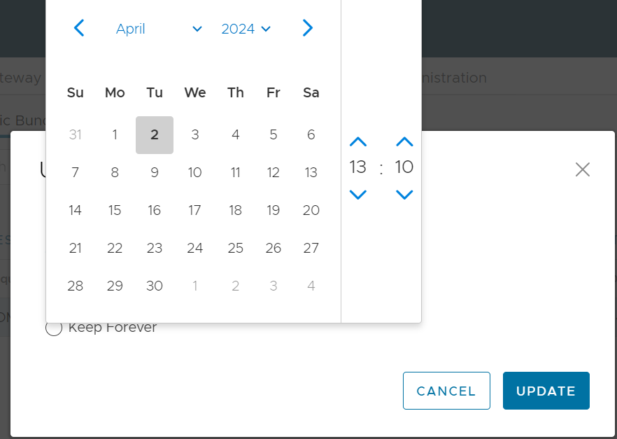
- You can also choose to keep the bundle indefinitely by checking the Keep Forever checkbox.
Figure 38. Update Cleanup Date 
- Select OK.
The Orchestrator Diagnostics table grid updates to reflect the changes to the Cleanup Date.
Figure 39. Table Grid Updates 
Database Statistics Tab
The Database Statistics tab provides read-only access to diagnostic bundle information.
If you require additional information, go to the Diagnostic Bundles tab, request a diagnostic bundle, and download it locally. For additional information, see Request Diagnostic Bundle.

| Field | Description |
|---|---|
| Database Sizes | Sizes of the Orchestrator databases. |
| Database Table Statistics | Statistical details of all tables in the Orchestrator database. |
| Database Storage Info | Storage details of the mounted locations. |
| Database Process List | The top 20 records of long-running SQL queries. |
| Database Status Variable | The status variables of the MySQL server. |
| Database System Variable | System variables of the MySQL server. |
| Database Engine Status | The InnoDB engine status of the MySQL server. |
System Metrics Monitoring
This section discusses System Metrics Monitoring on the Orchestrator.
Orchestrator System Metrics Monitoring Overview
sudo /opt/vc/scripts/vco_observability_manager.sh enable
sudo /opt/vc/scripts/vco_observability_manager.sh status
sudo /opt/vc/scripts/vco_observability_manager.sh disable
The Metrics Collector
| Metric Name | Description |
|---|---|
| inputs.cpu | Metrics about CPU usage. |
| inputs.mem | Metrics about memory usage. |
| inputs.net | Metrics about network interfaces. |
| inputs.system | Metrics about system load and uptime. |
| inputs.processes | The number of processes grouped by status. |
| inputs.disk | Metrics about disk usage. |
| inputs.diskio | Metrics about disk IO by device. |
| inputs.procstat | CPU and memory usage for specific processes. |
| inputs.nginx | Nginx's basic status information (ngx_http_stub_status_module). |
| inputs.mysql | Statistic data from the MySQL server. |
| inputs.clickhouse | Metrics from one or many ClickHouse servers. |
| inputs.redis | Metrics from one or many redis servers. |
| inputs.filecount | The number and total size of files in specified directories. |
| inputs.ntpq | Standard NTP query metrics (requires ntpq executable). |
| Inputs.x509_cert | Metrics from a SSL certificate. |
- sudo vi /etc/telegraf/telegraf.d/system_metrics_input.conf
- sudo systemctl restart telegraf
The Time-series Database
Prometheus is used to store the system metrics collected by Telegraf. The metrics data will be kept in the database for three weeks at the most. By default, Prometheus listens on port 9090. If you have an external monitoring tool, configure it to use the Prometheus database as a source so you can view Orchestrator system metrics in your monitoring UI.
Rate Limiting API Requests
When too many API requests are sent at once, system performance suffers. You can enable Rate Limiting, which imposes a limit on the number of API requests per user.
The Orchestrator uses certain defence mechanisms to curb API abuse and maintain system stability. API requests that exceed the allowed request limits are blocked and returned with HTTP 429 (Too many Requests). The system needs to go through a cool down period before making the requests again.
- Leaky bucket limiter– Smooths the burst of requests and only allows a pre-defined number of requests. This limiter takes care of limiting the number of requests allowed in a given time window.
- Concurrency limiter– Limits the number of requests that run in parallel, which can lead to concurrent requests fighting for resources and may result in long-running queries.
- A large number of active or concurrent requests.
- Sudden spikes in request volume.
- Requests that result in long-running queries on the Orchestrator holding system are being dropped.
- Handle HTTP 429 response code when requests exceed rate limits.
- The penalty time duration is 5000 ms when the rate limiter reaches the maximum allowed requests in a given period. If blocked, the clients are expected to have a cool down period of 5000 ms before making requests again. The requests made during the cool down period of 5000 ms will still be rate limited.
- Use shorter time intervals for time series APIs, which will not let the request expire due to long running queries.
- Prefer batch query methods to those that query individual Customers or Edges whenever possible.
Configure Rate Limiting Policies using System Properties
vco.api.rateLimit.enabledvco.api.rateLimit.mode.logOnlyvco.api.rateLimit.rules.globalvco.api.rateLimit.rules.enterprise.defaultvco.api.rateLimit.rules.enterpriseProxy.default
For additional information on the system properties, see List of System Properties.
Configure Rate Limiting Policies using APIs
enterpriseProxy/insertOrUpdateEnterpriseProxyRateLimits– Used to configure Partner-specific policies.enterprise/insertOrUpdateEnterpriseRateLimits– Used to configure Customer-specific policies.
For additional information on the APIs, see the VeloCloud API Guide.
Enterprise Deployment & Operations for Orchestrator
This section provides information about the available options to monitor, backup, and upgrade Enterprise On-Premises deployments in a two-day operation scenario.
Overview
- Isolation of the solution- The Arista Cloud Operations team does not have access to apply hotfixes and upgrades.
- Restrictions on change management limit the frequency of patching and upgrades.
- Inadequate or insufficient solution monitoring- This may occur due to a lack of personnel capable of managing the infrastructure, resulting in functional issues, slower problem resolution, and customer dissatisfaction.
This approach always requires a significant investment in people and time to manage, operate, and patch properly. The table below outlines key elements to consider when managing a system on-premises.
| System | Description | VeloCloud Hosted Responsibility | On-Premises Responsibility |
|---|---|---|---|
| SD-WAN Orchestration | Application QoS and link steering policy | Yes | Yes |
| Security policy for apps and SD-WAN appliances | Yes | Yes | |
| SD-WAN appliance provisioning and troubleshooting | Yes | Yes | |
| Handling of SD-WAN alerting and events | Yes | Yes | |
| Link performance and capacity monitoring | Yes | Yes | |
| Hypervisor | Monitoring / alerting | No | Yes |
| Compute and memory resourcing | No | Yes | |
| Virtual networking and storage | No | Yes | |
| Backup | No | Yes | |
| Replication | No | Yes | |
| Infrastructure | CPU, memory, compute | No | Yes |
| Switching and routing | No | Yes | |
| Monitoring and management systems | No | Yes | |
| Capacity planning | No | Yes | |
| Software upgrades/patching | No | Yes | |
| Troubleshooting application/infrastructure issues | No | Yes | |
| Backup and Infrastructure DR | Backup infrastructure | No | Yes |
| Regular testing of backup regime | No | Yes | |
| DR infrastructure | No | Yes | |
| DR testing | No | Yes |
See Day One Operations and Day Two Operations to continue your deployment.
Day One Operations
Deactivating the Cloud-init on the Orchestrator
It is not recommended to purge the cloud-init file with the command apt purge cloud-init (this procedure does not cause issues in the VeloCloud SD-WAN Controller). Purging the cloud-init file also erases some essential Orchestrator tools and scripts such as upgrade and backup scripts. If the purge command was used, you can restore the files using the following commands:
Configuring the NTP Timezone
The expectation is that the NTP offset is <= 15 milliseconds.
Orchestrator Storage
Additional Tasks
Day Two Operations
Orchestrator Backup
Remember that the Disaster Recovery feature or DR is the preferred recovery method. It provides a Recovery Point Objective of nearly zero, as all configurations on the Active Orchestrator is instantly replicated. For more details on the Disaster recovery feature, refer to the next section.
Backup Using the Embedded Script
The Orchestrator provides an in-built configuration backup mechanism to periodically Backup the configuration to recover from Operator errors or catastrophic failure of both the Active and Standby Orchestrator. The mechanism is script-driven and is located at /opt/vc/scripts/db_backup.sh.
The script essentially takes a database dump of the configuration data and events, while excluding some of the large monitoring tables during the database dump process. Once the script is executed, backup files are created in the local directory path provided as input to the above script.
- Mount a remote location and configure the backup script to it. The remote location should have the same storage as /store if flows are also being Backup.
- Before using the Backup Script, check the Disaster Recovery (DR) replication status from the Orchestrator replication page. They should be in sync, and no errors should be present.
- Additional to this, execute a MySQL query and check the replication lag.
- SHOW SLAVE STATUS \G
- In the above query, look at the field seconds_behind_master. Ideally, it should be zero, but under 10 would be sufficient as well.
- For the large Orchestrators, it is recommended to use the Standby for the Backup script execution. There will be no difference in the Backup that is generated from both Orchestrators.
Caveats- The Script only takes a backup of the configuration; flow stats or events are not included.
- Restoring the configuration requires assistance from the Support/Engineering team.
The Backup consists of two .gzs files, one containing the database schema definition and the other one containing the actual data without definition. The administrator should ensure that the backup directory location has enough disk space for the Backup.
Frequently Asked Questions
- How long does the Script take to run?
The duration of the Backup depends on the scale of the actual customer configuration. Since the monitoring tables are excluded from the Backup operation, it is expected that the configuration Backup operation will complete quickly. For a large Orchestrator with thousands of Edge and lots of historical events, it could take up to an hour, while a smaller Orchestrator should be completed within a few minutes.
- What is the recommended frequency to run the Backup script?
Depending on the size and time it takes to complete the initial backup, the Backup operation frequency can be determined. The Backup operation should be scheduled to run during off-peak hours to reduce the impact on Orchestrator resources.
- What if the root file system doesn't have enough space for the backup?
It is recommended that other mounted volumes are used to store the backup. Note, it is not a best practice to use the root filesystem for the backup.
- How does one verify if the Backup operation completed successfully?
The script stdout and stderr should be sufficient to determine the success or failure of the Backup operation. If the script invocation is automated, the exit code can determine the Backup operation's success or failure.
- How is the configuration recovered?
Currently, Arista requires that the customer work with Arista Support to recover the configuration data. Arista Support will help to recover the customer's configuration. Customers should refrain from making any additional configuration changes until the configuration is restored.
- What is the exact impact of executing this script?
Even though a backup of the configuration should have little impact on performance, there will be an increase in resource utilization for the MySQL process. It is recommended that the Backup be run during off-peak hours.
- Are any configuration changes allowed during the run of the backup operation?
It is safe to make configuration changes while the Backup operation is running. However, to ensure up-to-date backups, it is recommended that no configuration operations are done while the Backup is running.
- Can the configuration be restored on the original Orchestrator, or does it require a new Orchestrator?
Yes, the configuration can, and ideally should, be restored on the same Orchestrator if it is available. This will ensure that the monitoring data is utilized after the Restore operation is completed. If the original Orchestrator cannot be recovered and the Standby Orchestrator is down, the configuration can be restored on a new Orchestrator. In this instance, the monitoring data will be lost.
- What actions should be taken in case the configuration needs to be restored to a new Orchestrator?
Contact Arista Support for the recommended set of actions on the new Orchestrator as the steps vary depending on the actual deployment.
- Do Edges have to re-register on the newly restored Orchestrator?
No, Edges are not required to register on the new Orchestrator, as all needed information is preserved as part of the Backup.
Orchestrator Disaster Recovery
See Set Up Orchestrator Disaster Recovery for detailed instructions.
Upgrade Procedure for the Orchestrator
- Provide a screenshot of the replication dashboard of the Orchestrator.
Figure 41. Active Orchestrator Replication Dashboard 
Monitor Gateway Controllers
SD-WAN Controller Monitoring
You can monitor the status and usage data of Controllers available in the Operator portal.
The procedure is as follows:
- Select the Monitor tab to view the usage data of the selected Controller.
The Monitor tab of the selected Controller displays the following details:
Figure 42. Monitor Gateway Controller 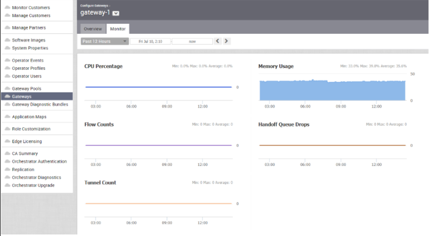
You can choose a specific period to view the Controller details for the selected duration at the top of the page.
The page displays a graphical representation of usage details of the following parameters for the period of selected time duration, along with the minimum, maximum, and average values.
Table 43. Usage Details Usage Description CPU Percentage Percentage of usage of CPU Memory Usage Percentage of usage of memory Flow Counts Count of traffic flow Handoff Queue Drops Count of packets dropped due to queued handoff Tunnel Count Count of tunnel sessions SD-WAN Gateway Controller Recommended Values to Monitor
The following list shows values that should be monitored and their thresholds. The list below is given as a start point, and it is not exhaustive. Some deployments may require assessing additional components such as flows, packet loss, etc.
Whenever a warning threshold is reached, it is recommended to review the current device scale configuration and add more resources if required. When a critical alarm is triggered, it is crucial to contact Arista Support representatives to check the solution and provide further advice.
Table 44. Thresholds Service Check Service Check Description Warn Threshold Critical Threshold CPU Load Check System Load. 60 80 Memory Checks the memory utilization buffer, cache, and used memory. 70 80 Tunnels Number of tunnels from connected Edges. 60% of max Scale 80% of max Scale Note: A sudden loss of all tunnels or an abnormal low quantity should also be a concern.
Handoff Drops Due to the busy nature of traffic through a Controller, occasional drops are expected. Consistent drops in specific queues may indicate a capacity problem. Disk Space Current disk utilization 40% Free 20% Free Controller NTP Check for Time offset Offset of 5 Seconds Offset of 10 Seconds
Orchestrator Integration with Monitoring Stacks
Before getting started, set up a time-based database and a dashboard/alerting agent. After this is complete, you can enable Telegraf in Orchestrator.
sudo /opt/vc/scripts/vco_observability_manager.sh enable
sudo /opt/vc/scripts/vco_observability_manager.sh status
sudo /opt/vc/scripts/vco_observability_manager.sh disable
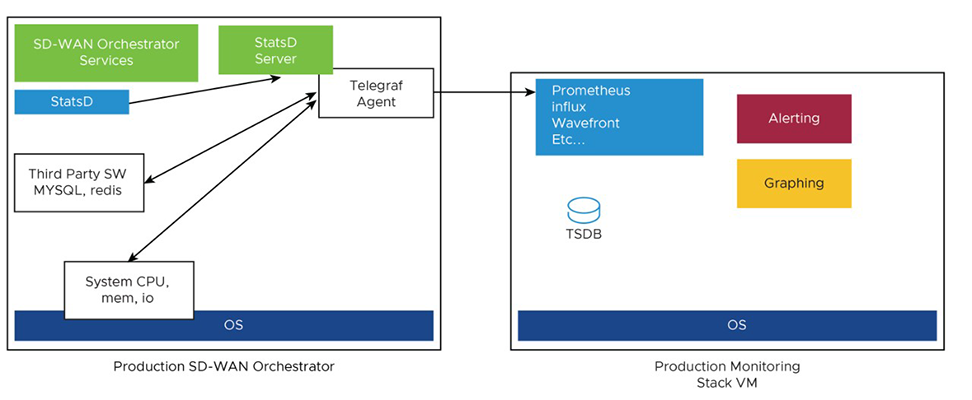
The Metrics Collector Telegraf is used as the Orchestrator system metrics collector with plugins to collect different system metrics. The following metrics are enabled by default.
| Metric Name | Description | Supported in Version |
|---|---|---|
| inputs.cpu | Metrics about CPU usage. | 3.4/4.0 |
| inputs.mem | Metrics about memory usage. | 3.4/4.0 |
| inputs.net | Metrics about network interfaces. | 4.0 |
| inputs.system | Metrics about system load and uptime. | 4.0 |
| inputs.processes | The number of processes grouped by status. | 4.0 |
| inputs.disk | Metrics about disk usage. | 4.0 |
| inputs.diskio | Metrics about disk IO by device. | 4.0 |
| inputs.procstat | CPU and memory usage for specific processes. | 4.0 |
| inputs.nginx | Nginx's basic status information (ngx_http_stub_status_module). | 4.0 |
| inputs.mysql | Statistic data from MySQL server. | 3.4/4.0 |
| inputs.redis | Metrics from one or many redis servers. | 3.4/4.0 |
| inputs.statds | API and system metrics. | 3.4/4.0 (additional metrics are included in 4.0) |
| inputs.filecount | The number and the total size of files in specified directories. | 4.0 |
| inputs.ntpq | Standard NTP query metrics, requires ntpq executable. | 4.0 |
| Inputs.x509_cert | Metrics from a SSL certificate. | 4.0 |
To activate more metrics or deactivate some enabled metrics, you can edit the Telegraf configuration file on the Orchestrator using the following commands:
sudo vi /etc/telegraf/telegraf.d/system_metrics_input.conf
sudo systemctl restart telegraf
- Time-series Database- A time Series Database can be used to store the system metrics collected by Telegraf. A time-series database (TSDB) is a database optimized for time series data.
- Dashboard and Alerting Agent- allows you to query, visualize, alert, and explore the data stored in the TSDB. The following image provides an example of a dashboard using Telegraph, a TSDB and a dashboard engine, created to monitor the solution.
Figure 44. Monitoring Dashboard 
Follow the instructions below to setup the time-series database.
- Add the iptables entry to allow for external monitoring systems to access to Telegraf port. The source IP address should be specified for security reasons.
The IP address of the external monitoring system is
191.168.0.200Add "-A INPUT-p tcp-m tcp--source 191.168.0.200--dport 9273-m comment--comment "allow telegraf port"-j ACCEPT" to /etc/iptables/rules.v4Figure 45. Add Ports 
- Ensure the
iptablesentry updated.Figure 46. IP Tables 
- Add the time-series database details in the Telegraf configuration. Create an output configuration file. For example, Prometheus uses the following:
/etc/telegraf/telegraf.d/prometheus_out.conf
Figure 47. Prometheus Example 
Monitor Values and Thresholds
| Service Check | Service Check Description | Warn Threshold | Critical Threshold |
|---|---|---|---|
| CPU Load | Check System Load – Telegraf input plugin: inputs.cpu. | 60 | 70 |
| Memory | Checks the memory utilization buffer, cache, and used memory – Telegraf input plugin: inputs.memory. | 70 | 80 |
| Disk Usage | Disk Utilization in the different Orchestrator partitions, /, /store, /store2 and /store3 (version 4.0 and onwards) – Telegraf input plugin: inputs.disk (version 4.0 and onwards). | 40% Free | 20% Free |
| MySQL Server | Checks MySQL Connections-Telegraf input plugin: inputs.mysql. | Above 80% of max connection define in mysql.conf(/etc/mysql/my.cnf) | |
| Orchestrator Time | Check for Time offset-Telegraf input plugin: inputs.ntpq (version 4.0 and onwards). | Offset of 5 Seconds | Offset of 10 Seconds |
| Orchestrator SSL Certificate | Checks Certificate Expiration- Telegraf input plugin: inputs.x509_cert (version 4.0 and onwards). | 60 Days | 30 Days |
| Orchestrator Internet (not applicable for MPLS only topologies) | Check for Internet access. | Response time > 5 secs | Response time > 10 secs |
| Orchestrator HTTP | Make sure HTTP on localhost is responding. | The localhost is not responding. | |
| Orchestrator Total Cert Count | Check Total – Example mysql query:
SELECT count(id) FROM VELOCLOUD_EDGE_CERTIFICATE WHERE validFrom <= NOW() AND validTo >=NOW()', 'SELECT count(id) FROM VELOCLOUD_GATEWAY_CERTIFICATE WHERE validFrom <= NOW() AND validTo >=NOW() |
CRL | When Total Cert count exceeds 5000 |
| DR Replication Status | Confirm the Standby Orchestrator is up-to-date. | Review that the DR Orchestrator is no more than 1000 seconds behind the Active Orchestrator.
Seconds_Behind_Master: from mysql command: show slave STATUS\G; |
|
| DR Replication Edge Gateway delta | Confirm that Edges and Gateways can talk to the DR Orchestrator.
Different values between the Active and the Standby Orchestrators can be due to a difference in the timezone in Edges and Gateways. |
The same amount of Edges talking with the Active Orchestrator should be able to reach the Standby Orchestrator. This value can be checked on the "replication" tab or via the API. | |
API Best Practices
Orchestrator Portal- The Orchestrator Portal allows network administrators (or scripts and applications acting on their behalf) to manage network and device configuration and query the current or historical network and device state. API clients may interact with the Portal via a JSON-RPC interface or a REST-like interface. It is possible to invoke all of the methods described in this document using either interface. There is no Portal functionality for which access is constrained exclusively to either JSON-RPC clients or REST-like ones.
Both interfaces accept exclusively HTTP POST requests. Both also expect that request bodies, contain JSON-formatted content consistent with RFC 2616. Clients are furthermore likely to formally assert where this is the case using the Content-Type request header, e.g., Content-Type: application/json.
Additional information about the VeloCloud SD-WAN API can be found here:
https://code.Arista.com/apis/1000/velocloud-sdwan-vco-api
- Wherever possible, aggregate API calls should be preferred to enterprise-specific ones, for example, a single call to
monitoring/getAggregateEdgeLinkMetricsmay be used to retrieve transport stats across all Edges concurrently. - VeloCloud requests that clients limit the number of API calls in flight at any given time to no more than 2-4. If a user feels there is a compelling reason to parallelize API calls, Arista requests that they contact Arista Support to discuss alternative solutions.
- Arista doesn't recommend polling the API for stats data more frequently than every 10 min. New stats data arrives at the Orchestrator every 5 minutes. Due to jitter in reporting/processing, clients polling every 5 minutes might observe "false-positive" cases where stats aren't reflected in API calls' results. You might get the best result using request intervals of 10 minutes or greater in duration.
- Avoid querying the same information twice.
- Use sleep between APIs.
- For complex software automations, run your scripts and evaluate the CPU/Memory impact. Then adjust as required.
Orchestrator Syslog Configuration
- Portal: The Portal process runs as an internal HTTP server downstream from NGINX. The Portal service handles incoming API requests, either from the Orchestrator web interface or from an HTTP/SDK client, primarily in a synchronous fashion. These requests allow authenticated users to configure, monitor, and manage the various services provided by the Orchestrator.
This log is very useful for AAA activities as it has all actions taken by users in the Orchestrator.
Log files:
/var/log/portal/velocloud.log(Logs all info, warn, and error logs) - Upload: The Upload process runs as an internal HTTP server downstream from NGINX. The Upload service handles incoming requests from Edges and Gateways, either synchronously or asynchronously. These requests primarily consist of activations, heartbeats, flow statistics, link statistics, and routing information sent by Edges and Gateways.
Log files:
/var/log/upload/velocloud.log(Logs all info, warn, and error logs) - Backend: Job runner that primarily runs scheduled or queued jobs. Scheduled jobs consist of cleanup, rollup, or status update activities. Queued jobs consist of processing link and flow statistics.
Log files:
/var/log/backend/velocloud.log(Logs all info, warn, and error logs)
Use the following steps to configure Orchestrator Syslog:
- Change the
enable:falsevalue to true for one or more of the servers. Change the Host IP and port accordingly to your implementation.Figure 48. Modify System Property 
Increasing Storage in the Orchestrator
- Ensure the same LVM distribution applies to the Standby Orchestrator.
- It is not recommended to reduce the size of the volumes once increased. Use thin provisioning instead.
- In 3.4, when increasing the disk size, the following percentage/value distribution may be used:
- “/” Volume: This volume is used for the operative system. Production Orchestrators are usually set to 140GBs and have from 40% to 60% usage.
- /store and /Store2: The proportion applied in production Orchestrators is close to 85% for /Store and 15% for /Store2.
The following guidelines in the table below should be used in the 4.x release and onwards.
| Instance Size | /store | /store2 | /store3 | /var/log |
|---|---|---|---|---|
| Small (5000 Edges) | 2 TB | 500 GB | 8 TB | 100 GB |
| Medium (10000 Edges) | 2 TB | 500 GB | 12 TB | 125 GB |
| Large (15000 Edges) | 2 TB | 500 GB | 16 TB | `150 GB |
Managing Certificates in the Orchestrator
Detailed instructions to configure the CA can be found in the official VeloCloud SD-WAN Operator documentation, under Install Orchestrator and Install an SSL Certificate.
- Management plane TLS 1.2 tunnels between the Orchestrator and Edge SD-WAN Controller.
- Control and Data plane IKEv2/IPsec tunnels between SD-WAN Edges and between Edge and SD-WAN Controller.
Certificate Revocation List
On Controllers with PKI enabled, revoked certificates are stored in a Certificate Revocation List (CRL). If this list grows too long, generally due to an issue with the Orchestrator Certificate Authority, the Controller's performance becomes impacted. The CRL should be less than 4,000 entries long.
vcadmin@vcg1-example:~$ openssl crl -in /etc/vc-public/vco-ca-crl.pem -text | grep 'Serial Number' | wc -l 14 vcadmin@vcg1-example:~
Support Interaction
- Diagnostic Bundles
While investigating an incident, a diagnostic bundle of the Orchestrator and SD-WAN Controller can be created. The resulting file will assist the Arista Support team to further analyze the events around an issue.
Figure 49. Gateway Diagnostic Bundles 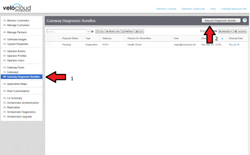
Figure 50. Request Diagnostic Bundles 
- Share Access with Support
On occasion assistance from Arista Support representatives for the Orchestrator and SD-WAN Controllers may be required.
Some common ways to grant access are:- Remote sessions with Support: The customer would either grant remote control to the SSH jump server or follow the Support representative's instructions.
- Creating an account for the Support team in the Orchestrator. This helps the Support team gather logs without customer interaction.
- Through the Bastion Host: SSH permissions and keys can be configured to allow the Support engineers to access the on-premises Orchestrator and SD-WAN Controller using a Bastion Host.
When contacting Arista SD-WAN Support to assist triaging an issue, include the data described in the table below.
| Required | Suggested |
|---|---|
| Partner Case Number | Issue Start/Stop |
| Partner Return Email/Phone | Impacted Flow SRC/DST IP |
| Orchestrator URL | Impacted Flow SRC/DST Port |
| Customer Name in Orchestrator | Flow Path (E2E, E2GW, Direct) |
| Customer Impact (High/Med/Low) | SD-WAN Gateway Name(s) |
| Edge Name(s) | Link to PCAP in the Orchestrator |
| Link to Diagnostic Bundle in Orchestrator | |
| Short Problem Statement | |
| Analysis & Requested Assistance |