
Access Point Overview
O-405 is a multi-radio 802.11be (Wi-Fi 7) access point. Refer the datasheet for additional information.
Front Panel
The front panel of the AP has 6 LEDs that indicate the status of various AP functions.
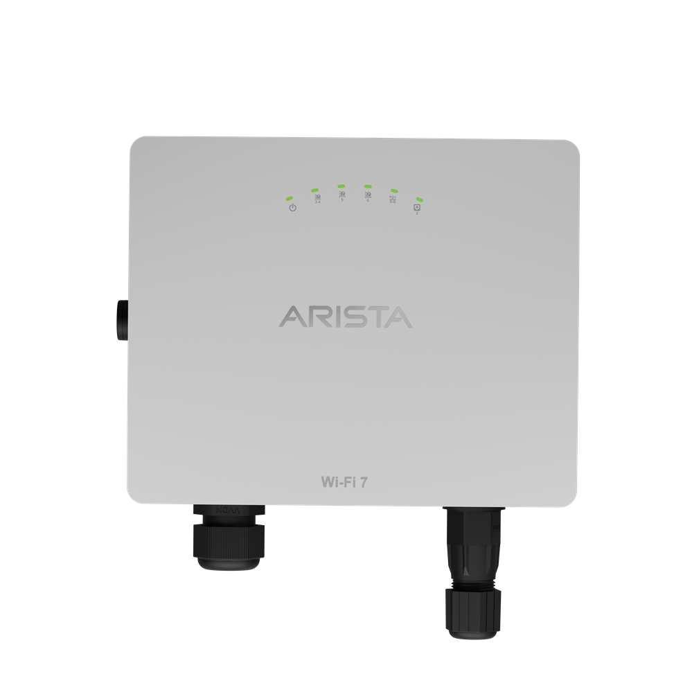
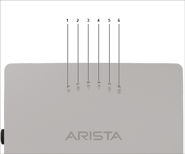
| 1 | Power | 2 | 2.4 GHz Radio | 3 | 5 GHz Radio |
| 4 | 6 GHz Radio | 5 | LAN1 PoE | 6 | SFP+ Port |
Power LED: The following table describes the Power LED states.
| Green | Red | |
|---|---|---|
| Solid | Running at full capability | Running at reduced capability |
| Blinking | Received IP address, but not connected to the server | Did not receive an IP address |
Reduced capability indicates that the AP is getting lower than the required maximum power from the PoE+ switch. It means the AP is getting 802.3af instead of 802.3at.
LAN1 LED: ON when the corresponding interface is up.
SFP+ LED: ON when the corresponding interface is up.
Radio LEDs: ON when the corresponding radio is operational.
Rear Panel
The bottom panel of the AP has a Reset pin hole and a Console port. It also has two ports:LAN1 and SFP+. Connect a wired LAN from a Switch or a hub to the LAN1/PoE+ port of the AP to power-on the AP. The LAN1 port supports the 802.3at power standard. Use an active wrench to open the LAN cap. Width of the LAN cap is 27 mm. Note that SFP+ port cannot be used to provide power to the AP.
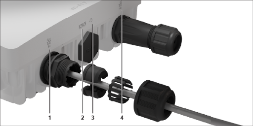
| 1 | LAN Port | 2 | Console | 3 | Reset pin hole | 4 | SFP+ Port |
| Port | Description | Connector Type | Speed/Protocol |
|---|---|---|---|
| LAN 1 | 5Gbps Ethernet with PoE+ compliant. LAN 1 powers the AP. LAN1 can also be used to provide the Internet connection if SFP+ port is unused. MACsec capable. | RJ-45 | 100M/1000Mbps/2.5G/5Gbps Ethernet. Recommended cable CAT6A |
| SFP+ | 10 Gbps SFP+. It cannot be used to power the AP. It can only be used to provide Internet connection to the AP. | SFP+ | 10Gbps/1Gbps SFP Optical cable |
| Reset | Reset to factory default settings port. Hold down and power cycle the device to reset. | Pinhole push button | N/A |
| Console | Establish ‘config shell’ terminal session via serial connection. | RJ-45 |
|
- Resets the Config shell password config.
- Erases the server discovery value and changes it to the default, redirector.online.spectraguard.net (primary) and wifi-security-server (secondary).
- Lose all the VLAN configurations.
- If the AP has a static IP, reset function erases the IP address and sets the AP to DHCP mode. The factory default IP address of the AP uses 169.254.11.74.