Powering the Modular Switch
Installation of this equipment must comply with local and national electrical codes. Consult with the appropriate regulatory agencies and inspection authorities to ensure compliance if necessary.
L'installation de cet équipement doit être conforme aux codes électriques locaux et nationaux. Consultez les agences de réglementation et les autorités d'inspection appropriées pour garantir la conformité si nécessaire.
The switch operates with multiple power supplies. Refer to Table 1 for information regarding your specific system. Table 2, and Table 3 list the quantities of modules each chassis can contain and the minimum operating requirements for each model.
| Switch Model | Chassis Capacity (Power Supply Units) | Minimum Operating Requirements (non-redundant power) |
|---|---|---|
| DCS-7358X4 | 4 | 1 active circuit |
| DCS-7368X4 | 4 | 1 active circuit |
| DCS-7289R3A(1) | 4 | 1 active circuit |
(1): Some configurations could require more than one active circuit.
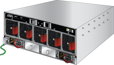
Rear Panels displays the location of the power supplies on the switch.
This chapter includes sections that describe the procedure for grounding and cabling power supplies. After completing the instructions for your switch, proceed to Connecting Serial and Management Cables.
Read all installation instructions before connecting the system to the power source.
Lire toutes les instructions d'installation avant de brancher le système à la source d'alimentation.
- Non-Redundant Configuration: Provide power to the minimum required power inputs.
- Redundant Power Supply Configuration: Connecting power to modules over minimum requirements protects the switch against failed modules and can provide grid-level redundancy.
- Power down the Switch: Remove all power cords from the power input sockets.
This equipment must be grounded. Never defeat the ground conductor. This unit requires over-current protection.
Cet équipement doit être mis à la terre. Ne jamais modifier le conducteur de terre. Cet appareil nécessite de protection contre les surintensités.
Cabling the AC Power Supply
Grounding the Switch
After mounting the switch into the rack, connect the switch to the data center ground. The grounding pads are located on the rear of the switch. It would help if you used a right-angle ground lug to attach the chassis ground wire and route it to the data center ground, as shown in the following figure.
Grounding wires and grounding lugs (M4 x 0.7) are not supplied. Wire size should meet local and national installation requirements. Commercially available 6 AWG wire is recommended for installations in the U.S.
À la terre et de mise à la terre fils cosses (M4 x 0.7) ne sont pas fournis. Calibre des fils doit satisfaire des exigences de l’installation locale et nationale. Disponible dans le commerce des câbles 6 AWG sont recommandé pour les installations aux États-Unis.
After the switch is grounded, ESD wrist straps can be grounded by connecting them to the ESD port on either the rear or the front of the switch, as shown in the following figures.
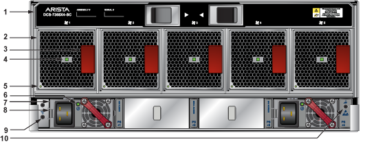
| 1 | Switch Card Module Release Handle | 6 | PSU Status LED |
| 2 | Fan | 7 | PSU |
| 3 | Fan Release Handle | 8 | PSU Release Handle |
| 4 | Fan Installation Indicator | 9 | Ground |
| 5 | Fan Status LED | 10 | ESD |
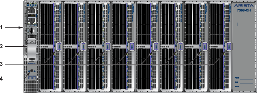
| 1 | Supervisor Module | 3 | Linecard Ejector Latch |
| 2 | Supervisor Ejector Latch | 4 | ESD |
Connecting the Power Cables to an AC Power Supply
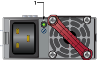
| 1 | Power Supply Status LED |
The power supplies require power cables that comply with an IEC-320 C19 plug. The accessory kit provides 14 AWG, C19, to C20 power cables.
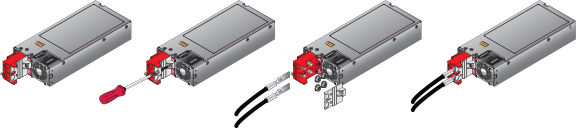
To insert a power cable:
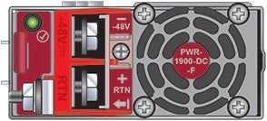
DC Power Supplies
The following figure displays a DC power supply module.
A disconnect device must be provided as part of the installation.
Un dispositif de sectionnement doit être fourni dans le cadre de l'installation.
Ensure power is removed from DC circuits before performing any installation actions. Locate the disconnect device, circuit breakers, or fuses on DC power lines servicing the circuits. Turn off the power line circuits or remove the fuses.
Pouvoir assurer qu'il est retiré de circuits DC avant d'effectuer des actions d'installation . Localiser les disjoncteurs ou des fusibles sur les lignes de courant continu desservant les circuits. Coupez les circuits de lignes d'alimentation ou retirer les fusibles.
Wire size must comply with local and national requirements and electrical codes. Use only copper wire.
Le calibre du fil doit être conforme aux exigences locales et nationales et les codes électriques. Utiliser du fil de cuivre.
Apply ground connection to the switch first during installation and remove last when removing power.
Appliquer connexion à la terre à l'interrupteur premier lors de l'installation et de supprimer la dernière alimentation lors du débranchement.
Wire and Lug Preparation
- Crimp the lugs with the proper tool, and ensure that the tubing extends over the barrel of the lugs and the insulation on the wires. The following figure shows an example lug.
Figure 6. Lug Preparation
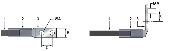
1 Insulated wire A 1/4” 2 Heat-shrink tubing B 1/2” 3 Lug C 5/8”
Connecting a DC Power Supply to Power Source
- Replace the terminal covers as required.
Figure 7. DC PSU Connection Example