Taiwan RoHS Information
This appendix provides Taiwan RoHS information for appliances covered by this guide.
For Taiwan BSMI RoHS Table, go to https://www.arista.com/assets/data/pdf/AristaBSMIRoHS.pdf.
This appendix provides Taiwan RoHS information for appliances covered by this guide.
For Taiwan BSMI RoHS Table, go to https://www.arista.com/assets/data/pdf/AristaBSMIRoHS.pdf.
This appendix lists the Regulatory Model Numbers (RMNs), where applicable, for the product models for the appliances described in this document.
| Regulatory Model Number (RMN) | Product Number(s) |
|---|---|
| AN2204, CAR-4040-5200-E90 | CCA-ETM-Q20 |
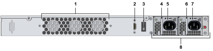
| 1 | Fans | 5 | Power supply socket |
| 2 | Video out (HDMI) | 6 | PSU handle |
| 3 | Power switch | 7 | Power supply socket |
| 4 | PSU handle | 8 | Power supply units |
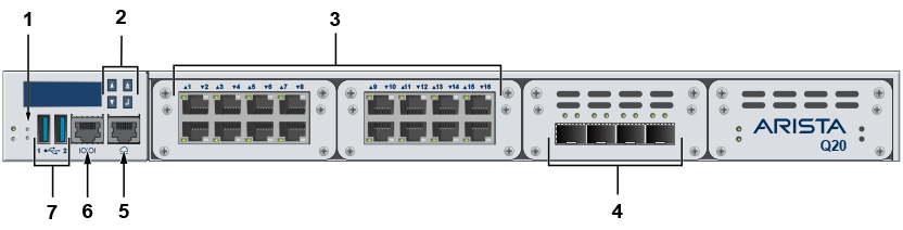
| 1 | Reset button | 5 | Console port |
| 2 | LCD controls | 6 | Internet port |
| 3 | LAN ports | 7 | USB ports |
| 4 | SFP+ LAN ports |
Each appliance provides an accessory kit that contains parts that are required to install the appliance. This section lists the installation parts contained in the appliance accessory kit.
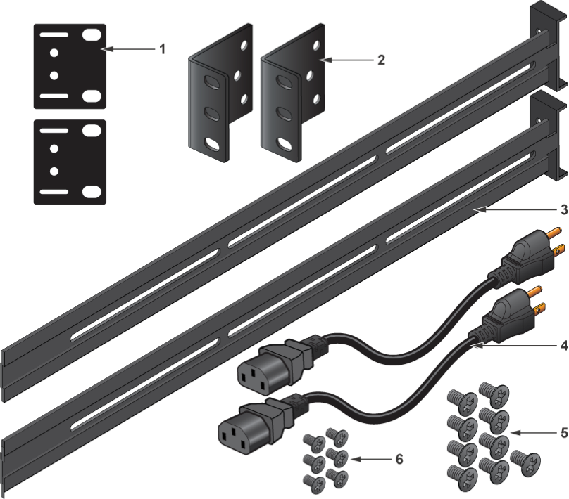
| 1 | Back bracket | 4 | Power cable |
| 2 | Mounting bracket | 5 | Racking mounting screws |
| 3 | Mounting rail | 6 | Appliance mounting screws |
This section describes the front panel LED status of the CCA-ETM-Q20 appliance.
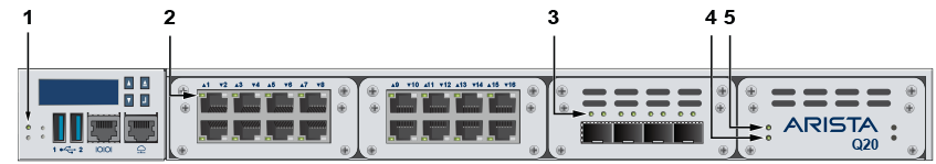
| 1 | Power | 4 | Storage activity |
| 2 | Port indicator | 5 | Storage power |
| 3 | LAN port indicators |
This section describes the rear panel LED status of the CCA-ETM-Q20 appliance.
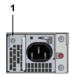
| 1 | Power indicator |
You can manage your appliance using the Edge Threat Management Dashboard or from the local network.
Connect an Ethernet cable from your Internet provider modem or router to the designated Internet port.
Connect an Ethernet cable from your management computer or LAN switch to port 1.
Plug in a power cable to an AC power source and connect it to a power input on the rear panel.
The appliance is mounted onto a four-post rack by preparing the chassis for mounting, then securing the appliance to the front posts using the mounting brackets, followed by securing it to the rear posts.
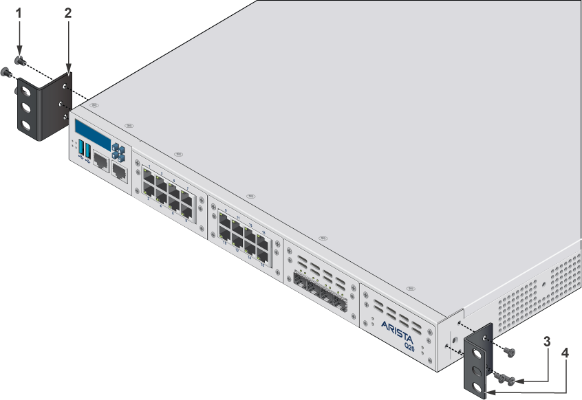
| 1 | Mounting screws | 3 | Mounting screws |
| 2 | Left bracket | 4 | Right bracket |
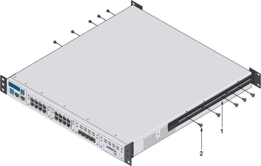
| 1 | Mounting rail | 2 | Mounting screws |
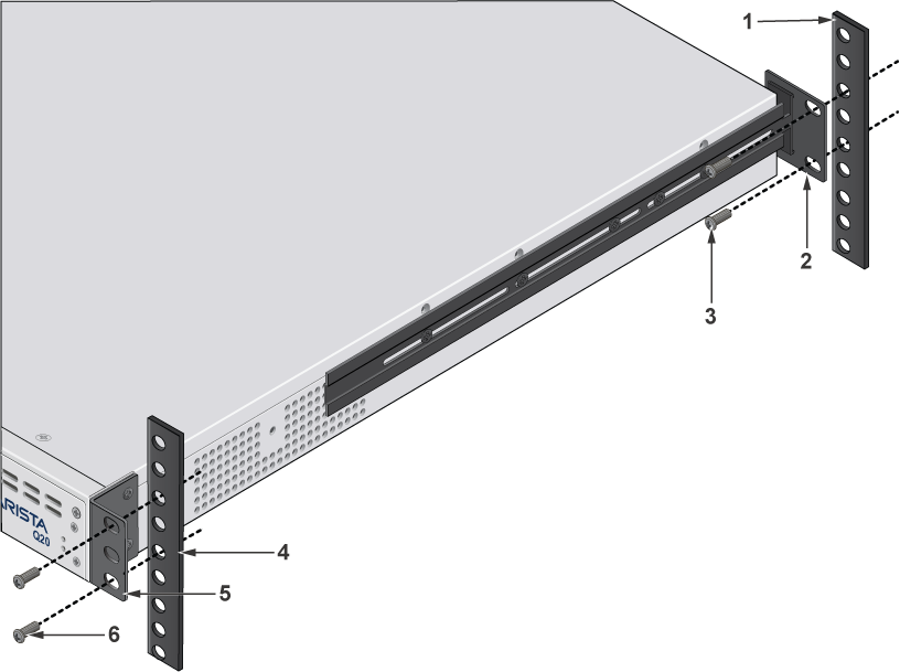
| 1 | Back rack post | 4 | Front rack post |
| 2 | Back bracket | 5 | Front bracket |
| 3 | Mounting screws | 6 | Mounting screws |
This section describes the initial setup and preparation for installing the CCA-ETM-Q20.
This chapters contains the following topics:
The following criteria should be considered when selecting a site to install the appliance.
Pour empêcher l’interrupteur de surchauffe, ne pas utiliser il dans une zone où la température ambiante est supérieure à 40°C (104°F).
When mounting the appliance in a partially filled rack, load the rack from bottom to top, with the heaviest equipment at the bottom. Load the appliance at the bottom if it is the only item in the rack.
Toutes les connexions d’alimentation doivent être enlevées pour hors tension l’appareil.
Each appliance provides an accessory kit that contains parts that are required to install the appliance. The accessory parts list is shown at Parts List.
In addition to the accessory kit, the following tools and equipment are required to install the appliance:
Accessory kit does not include screws for attaching the appliance to the equipment rack. When installing the appliance into an equipment rack with unthreaded post holes, nuts are also required to secure the appliance to the rack posts.