Taiwan RoHS Information
This section provides the Taiwan RoHS information for switches covered by this guide.

This section provides the Taiwan RoHS information for switches covered by this guide.

The following table lists the regulatory model numbers (RMNs), where applicable, for the product models for the switches described in this document
| Regulatory Model (RMN) | Product Number(s) |
|---|---|
| DCS-7388 | DCS-7388X5 |
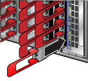
There is a linecard and supervisor removal tool to facilitate the removal and installation of linecards and supervisor modules. Use the tool as a sleeve on the release handle. It is mounted on the supervisor module Front Panels. Replace the tool after each use.
The switch card module is accessible from the rear of the switch as shown in Rear Panels. Refer to the following figure for more details on the removal and replacement of the switch card module.

| 1 | Switch Card Release Handle (Swing Arm) | 2 | Switch Card Release Buttons |
The module includes lock-levers that secure it to the chassis. The module and the lock levers are easily damaged by improperly removing, inserting, or handling. Use caution while lifting or moving the module after it is removed from the chassis.
The switch card module can include the fans and the power supplies. The release handle is a swing arm that is used for unseating and seating the switch card module.
Follow the steps listed below to remove the switch card module from the switch chassis.
The module insertion process is the inverse of the removal procedure. Follow the steps listed below to insert the switch card module into a chassis.
The power supplies are accessible from the rear of the switch (Rear Panels). Refer to the following figure for more details on the removal and replacement of a power supply unit.
The following steps are required when removing power supplies from a switch.
You must make space for installing the power supply by removing an existing one (Removing a Power Supply).
The fan modules are accessible from the rear of the switch as shown in Rear Panels. Refer to the following figure for more details on the removal and replacement of a fan module.
The following steps are required when removing or replacing fans from a switch.
You must make space for installing the fan module by removing an existing one (Removing a Fan Module).
The supervisor module is accessible from the front of the switch as shown in Front Panels. Refer to the following figure for more details on the removal and replacement of a supervisor module.
The supervisor module has a release handle with a push button latch indicator. The ejector tool works for both the linecards and the supervisor.
Perform the following steps to remove the module.
You must make space for installing the module by removing an existing one (Removing Supervisor Module). Perform the following steps to install the module.
The linecards are accessible from the front of the switch as shown in Front Panels. The linecards are hot-swappable. You must take into account that the linecard you are inserting is compatible with the switch and the linecard that you are replacing. Refer to the following figure for more details on the removal and replacement of a linecard module.
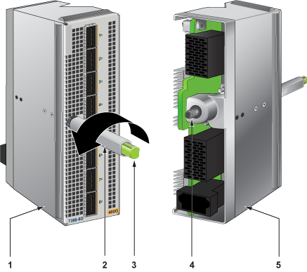
| 1 | Linecard Metal | 3 | Latch Indicator Button | 5 | Linecard Metal |
| 2 | Ejector (Release) Handle | 4 | Engaging and Aligning, Geared Screw |
Perform the following steps to remove a linecard.
You must make space for installing the linecard by removing an existing one (Removing Linecard) from a linecard slot available on the switch.
For more information about supported optical transceivers, refer to https://www.arista.com/en/products/transceivers-cables.
The following illustrations display the linecards supported by modular switches covered by this guide.
.png)
| 1 | Linecard | 3 | Linecard Status LED | 5 | Port Status LEDs |
| 2 | Linecard Ejector (Release) Handle | 4 | Linecard Ports |
.png)
| 1 | Linecard | 3 | Linecard Status LED | 5 | Port Status LEDs |
| 2 | Linecard Ejector (Release) Handle | 4 | Linecard Ports |
The following illustration displays the rear panel of all switches covered by this guide.
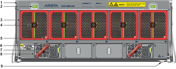
| 1 | Switch Card Module Release Handle | 4 | Fan Module Release | 7 | PSU Release |
| 2 | Switch Card Module Release Buttons | 5 | Fan Status LED | 8 | PSU |
| 3 | Fan | 6 | PSU Status LED | 9 | Ground |
The following illustration displays the front panel of all switches covered by this guide.
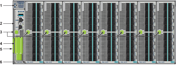
| 1 | ESD Attach Point | 3 | Supervisor and Linecard Ejector Handle (Release) and Latch Indicator Button | 5 | Pull Tag (for Switch Information) |
| 2 | Supervisor Module | 4 | Supervisor and Linecard Removal Tool | 6 | Linecard |
Each switch provides an accessory kit that contains parts required to install the switch into a four-post rack. The following sections list the installation parts provided by the accessory kit.
| Quantity | Description |
|---|---|
| One for each AC power supply module supplied with switch. | Power cables: TBD |
| One | RJ-45 Patch Panel Cables, 2 meters. |
| One | RJ-45 to DB9 Adapter Cable, 2 meters. |

| Quantity | Description |
|---|---|
| Two | Mounting Ears |
| One | Left shelf |
| One | Right shelf |
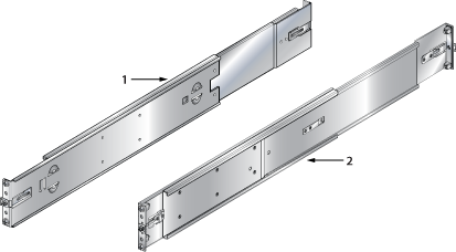
| 1 | Left Shelf | 2 | Right Shelf |
The supervisor displays switch component status and contains Ethernet management and console ports. The supervisor location is on the Front Panels of the switch.
The supervisor provides one serial console port, one Ethernet management port, and one USB port. Four LEDs on the top edge report system status, fan status, power status, and switch module status. The following figure shows the supervisor module status LEDs.

| 1 | System Status LED | 3 | Power Supply Status LED |
| 2 | Fan Status LED | 4 | Switch Card Status LED |
Supervisor Status LEDs
The following table interprets the states of the LED indicators on the supervisor module. When error conditions are indicated, refer to LEDs on the specified components to determine the condition’s source.
| LED Name | LED State | Module State |
|---|---|---|
| Power Supply | Green | All powered modules are operating normally. |
| Red | At least one module has failed. | |
| System | Green | All linecards are operating normally. |
| Red | At least one linecard has failed. | |
| Switch Card | Green | Module is operating normally. |
| Red | Module has failed. | |
| Fan | Amber | At least one fan is missing or has failed. |
| Green | All modules are operating normally. | |
| Red | There are insufficient functional fans installed in the switch. |
(1): If all Status LEDs are OFF, check the following: power feeds are live, power supplies are installed, Switch Card is properly seated, and Supervisor is properly seated. The system will not power up unless all four of these conditions are valid.
Each linecard module provides one status LED plus LEDs for each port on the card.
The following figure displays the status LED and port LEDs on the DCS-7388-16CD linecard. Arrows indicate the port status being displayed by the corresponding port status LED.
.png)
| 1 | Linecard | 3 | Linecard Status LED | 5 | Port Status LEDs |
| 2 | Linecard Ejector (Release) Handle | 4 | Linecard Ports |
The Linecard Status LED is in the center of the DCS-7388-16CD. The following tables interpret the states of the Status LED and the port LED.
| LED State | Status |
|---|---|
| Off | Linecard not inserted. |
| Green | Linecard operating normally. |
| Yellow (amber/orange) | Linecard administratively shut down. |
| Red | Linecard has failed. |
| LED State | Status |
|---|---|
| Off | Port link is down. |
| Green | Port link is up. |
| Yellow (amber/orange) | Port is disabled in the software. |
| LED State | Status |
|---|---|
| Off | Port link is down for enabled interfaces. |
| Green | Port link is up for enabled interfaces and all links are good. |
| Yellow (amber/orange) | Port is disabled in the software for all interfaces or a link is bad. |
The fan modules are inserted into the switch card module. Each switch contains one switch card and five fan modules accessible from the Rear Panels of the switch.
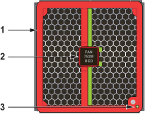
| 1 | Fan Airflow Direction Indicator Bezel Color | 2 | Fan Release Handle | 3 | Fan Status LED |
The following table interprets the states of the Fan Status LED.
| LED State | Status |
|---|---|
| Off | The module is inserted but not receiving power – it may not be properly seated. |
| Green | The module is operating normally. |
| Red | The module has failed. |
Power Supply LEDs are on power supply modules. The power supply modules for all switches are accessible from the Rear Panels of the switch.
The following figure displays a power supply module.
The power supply handle indicates the power supply airflow direction. Verify the airflow direction of all fan and power modules. All modules should have the same color handles.

| 1 | Power Supply Status LED |
The following table interprets the states of the Power Supply Status LED.
| LED | Status |
|---|---|
| Green | Power Supply module operating normally. |
| Off | No AC power to the module. |
| Red | Module has faulted. |
| Blinking Green | PSU has AC power but hasn't been enabled by the system - indicates that either the power supply or the Switch Module isn't fully inserted. |
Arista switches ship from the factory in Zero Touch Provisioning (ZTP) mode. ZTP configures the switch without user intervention by downloading a startup configuration file or a boot script from a location specified by a DHCP server.
To manually configure a switch, ZTP is bypassed. The initial configuration provides one username (admin) accessible only through the console port because it has no password.
When bypassing ZTP, initial switch access requires logging in as admin, with no password, through the console port. Then you can configure an admin password and other password protected usernames.
This manual configuration procedure cancels ZTP mode, logs into the switch, assigns a password to admin, assigns an IP address to the management port, and defines a default route to a network gateway.
Supervisor module contains the console, management, and USB ports. The following figure displays port locations on DCS-7388-SUP-D supervisor.

| 1 | USB Port | 3 | Ethernet Management Port | 5 | Torque Clutch Tool (shared by Supervisor and Linecards) |
| 2 | Console Port (Serial) | 4 | Supervisor Release |
Ethernet management port: Connect to 10/100/1000 management network with RJ-45 cable.
Connect cables as required to line card module ports. Supervisor and line card module ejectors on the front of the chassis assist with cable management.
Excessive bending can damage interface cables, especially optical cables.
Flexion excessive peut endommager les câbles d'interface, en particulier les câbles optiques.
Install required QSFP28, QSFP-DD, and OSFP optic modules in linecard module ports.
